
METU ROVER Power Control: UDP Relay Switching with W5500 EVB Pico
UDP-based relay controller for a university rover—receives JSON commands over Ethernet and switches power to rover subsystems via W5500 EVB Pico.
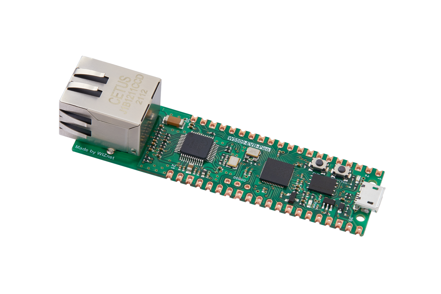
WIZnet - W5500-EVB-Pico
x 1
A Rover's Lifeline: Why Power Control Matters
In a competition rover, every subsystem — wheels, robotic arm, science instruments, communication — draws power from a shared battery bus. Controlling which subsystem receives power, and when, is not just a convenience; it is a safety-critical function. A motor driver fault can stall the entire vehicle. A science module left powered during transit wastes precious battery capacity. The ability to remotely toggle and restart subsystems over the network becomes the rover's lifeline.
This project implements exactly that layer for the METU ROVER, a student-built competition rover from Middle East Technical University (METU) that competes in the European Rover Challenge (ERC). The author, Mustafa Gasimzada, extracted this module from the team's larger private codebase and published it as a standalone, reusable piece of embedded engineering.
"Over the past year I've been working on a large-scale autonomous rover project as part of a team. The full system — central navigation, sensor fusion, communication stack, everything — lives in a private team repository that I can't share publicly. This is one module from that system." — README.md
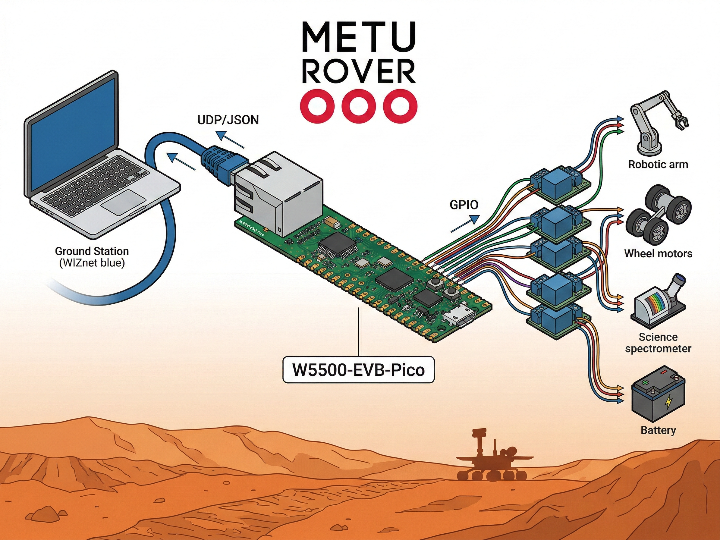
System Architecture: Ground Station → Ethernet → Relays
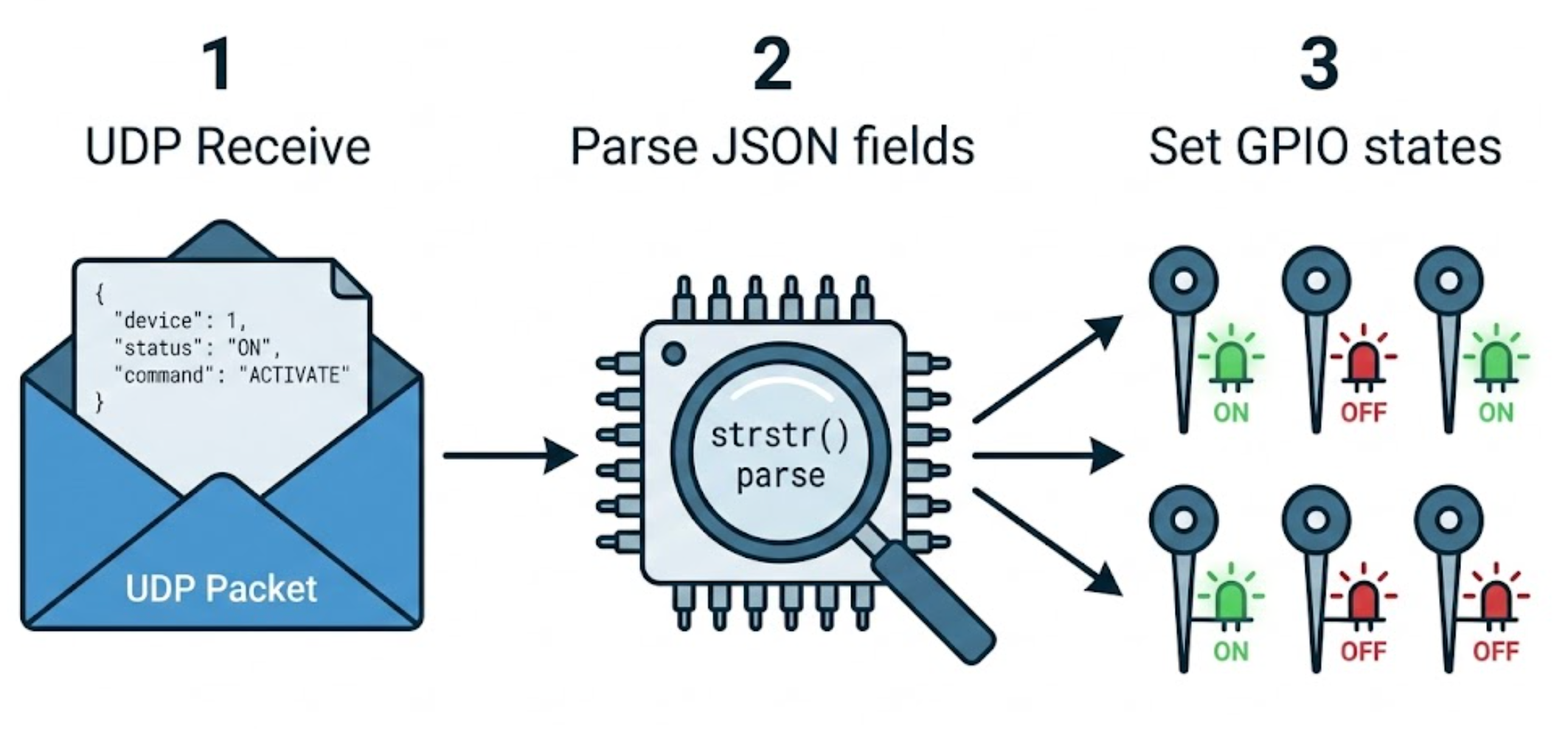
The data flow is straightforward and deterministic. A ground station (or any UDP client on the rover's internal network) sends a JSON-formatted command to the W5500-EVB-Pico at a static IP address (10.42.0.50) on port 5050. The Pico parses the JSON, maps each field to the corresponding GPIO pin, and drives the relay HIGH or LOW.
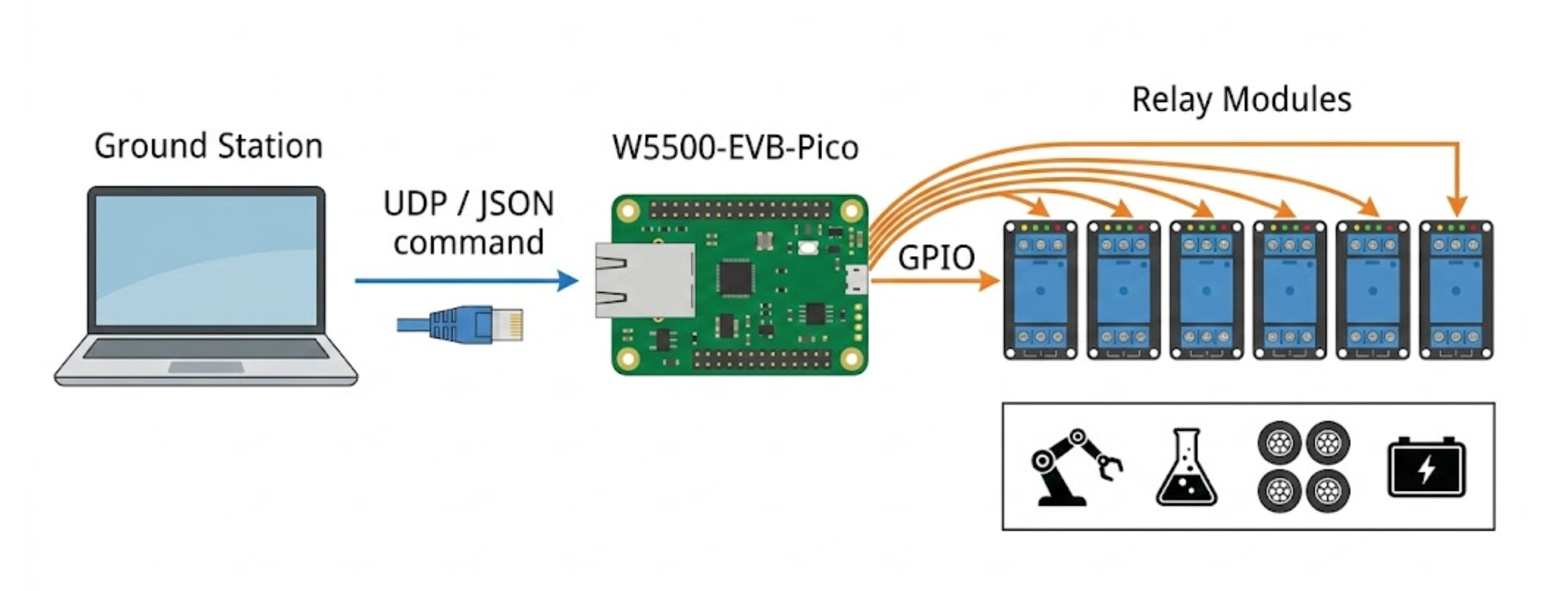
The board responds with the current state of all relays and a counter/timestamp, enabling the ground station to confirm command execution — a lightweight form of closed-loop feedback.
Two Relay Modes: Normal and Pulse
Not all relays behave the same way. The project implements two distinct relay strategies:
Normal Relay — The GPIO is set HIGH or LOW and stays there until a new command arrives. This is used for subsystems that require continuous power: the robot arm (GPIO 8), science system (GPIO 7), and individual wheel motors (GPIO 5, 6, 10, 11).
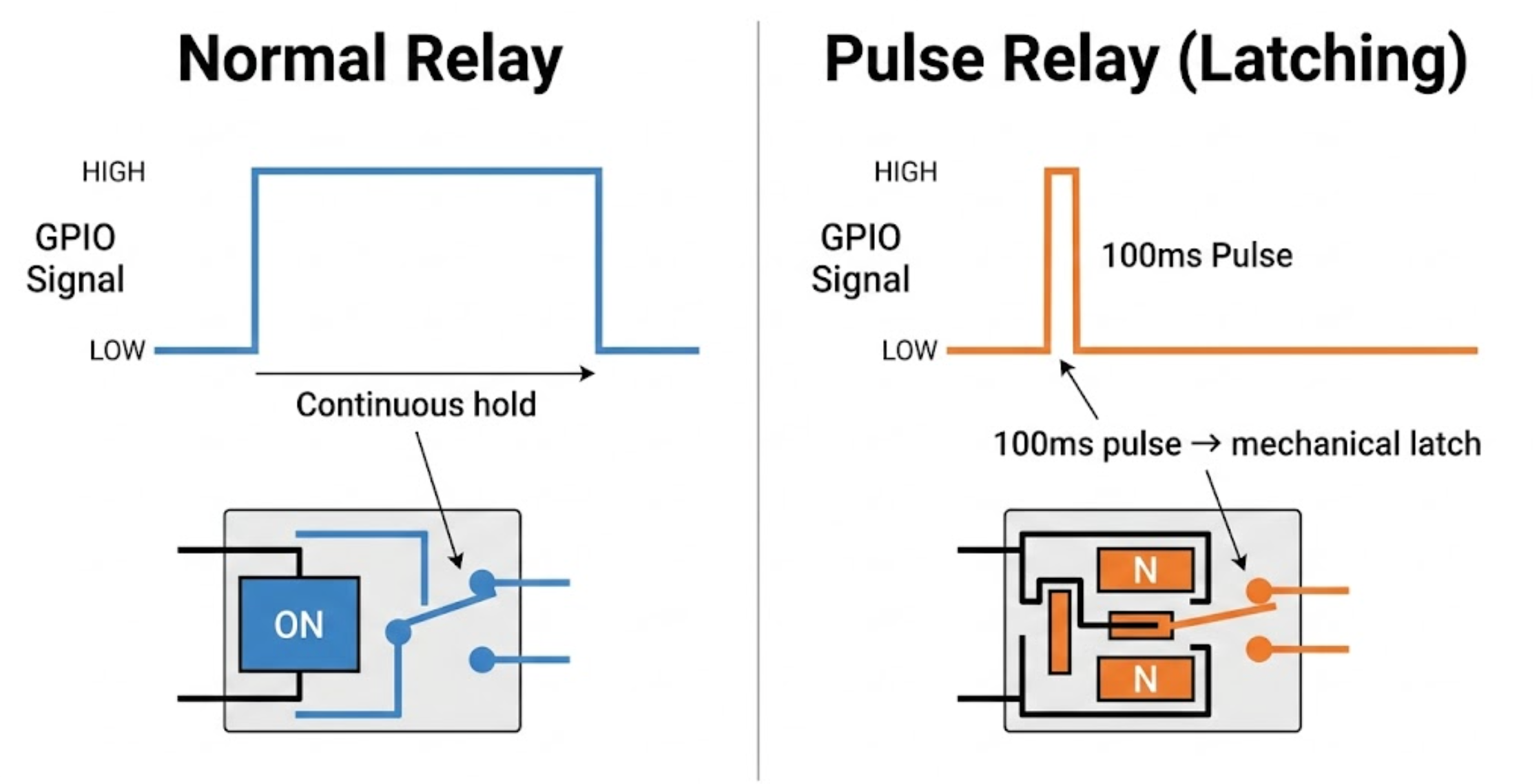
Pulse Relay — Instead of holding a state, the GPIO sends a brief 100 ms pulse on state change. This is designed for latching relays that mechanically hold their state without continuous current. The main power bus (GPIO 4) and bulk power (GPIO 3) use this mode. Latching relays are a smart choice for the primary power distribution: they consume zero quiescent current once set, preserving battery life in a competition scenario where every milliamp-hour counts.
Wheel Restart: Recovering from Motor Driver Faults
A particularly practical feature is the wheel restart sequence. By sending {"wheels_restart": 1}, the operator triggers a power-cycle on all four wheel relays: power is cut, the system waits 1 second, then power is restored. This is a common recovery strategy for brushed DC motor drivers that can latch into a fault state after overcurrent events — rather than requiring physical intervention on the field, a single UDP command resets them remotely.
JSON Command Parsing: Lightweight by Design
The README notes that JSON parsing uses strstr — a deliberate engineering choice for a constrained microcontroller. Rather than pulling in a full JSON parser library (which would add code size and potential dynamic allocation), simple string searching locates field names and extracts the following integer value. On an RP2040 with 264 KB of SRAM and no operating system, avoiding malloc/free entirely is a defensive strategy against heap fragmentation and memory leaks during long mission runs.
Example command:
{"robot_arm": 1, "science_system": 0, "wheels": 1, "all_power": 1, "bulk_power": 0}

Example response:
{"counter": 42, "robot_arm": 1, "science_system": 0, "wheels": 1, "all_power": 1, "bulk_power": 0, "timestamp": 1234567}
Why W5500 for a Rover?
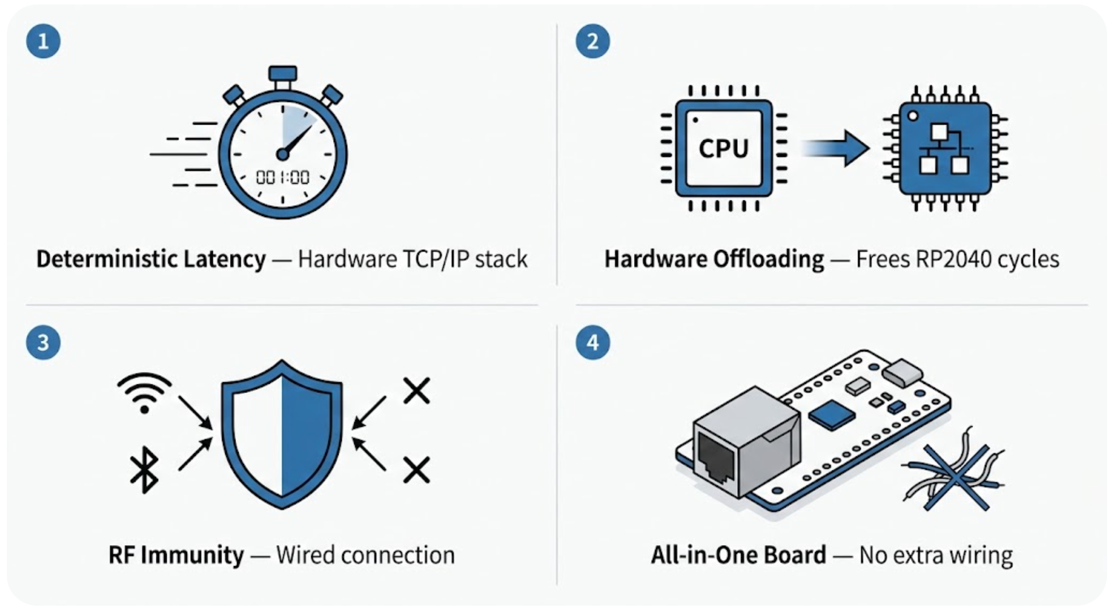
The choice of wired Ethernet via W5500 — rather than Wi-Fi — is deliberate and well-suited to this application:
Deterministic latency. The W5500's hardwired TCP/IP stack processes UDP packets in hardware, not in a software stack competing for MCU cycles. For a safety-critical power control node, predictable sub-millisecond response time matters. Wi-Fi's variable latency, retransmissions, and association issues are unacceptable for a system that controls whether the rover's wheels have power.
Hardware offloading. The W5500 handles the entire TCP/IP and UDP stack internally with 8 independent hardware sockets and 32 KB of buffer memory. The RP2040 only needs to communicate via SPI to send and receive UDP datagrams — freeing all CPU cycles for GPIO control and JSON parsing. There is no networking code competing with relay timing.
Reliability in RF-noisy environments. Competition rover fields are dense with radio signals from dozens of teams. A wired Ethernet connection through the rover's internal harness is immune to RF interference, providing a reliable communication backbone for critical control messages.
Simplicity of integration. The W5500-EVB-Pico combines the RP2040 MCU and W5500 Ethernet on a single board with a built-in RJ45 jack. No additional wiring, level shifters, or antenna tuning is needed. Drop it in, assign a static IP, and it works.
Build and Deployment
The project integrates with the official WIZnet Pico C SDK. Building requires cloning the SDK repository, placing this project under examples/relay_control/, and running the standard CMake build flow:
mkdir build && cd build
cmake .. -DBOARD_NAME=W5500_EVB_PICO
make relay_control
Flashing is done by holding the BOOTSEL button on the Pico while plugging in USB, then copying the generated .uf2 file to the mass storage device that appears. No special programmer is required.
Project Context: METU ROVER and the European Rover Challenge
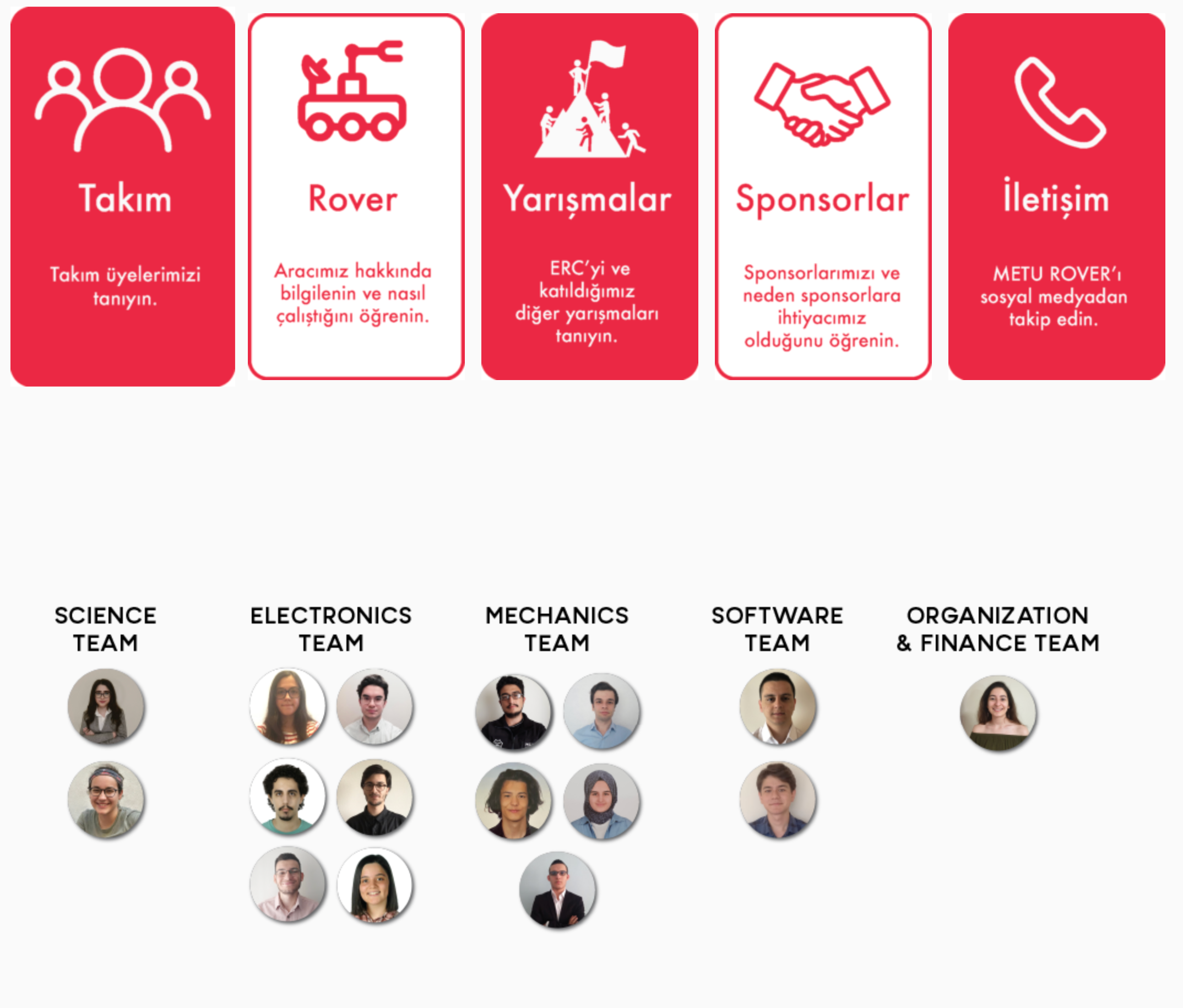
METU ROVER is a student project team at Middle East Technical University operating since 2018 under the Mechanical Engineering and Innovation Society. The team fields approximately 40 members across sub-teams covering mechanics, embedded software, electronics, science, and organization. They participate in the European Rover Challenge (ERC), an international competition where university teams design and operate rovers on simulated Martian terrain, performing tasks including autonomous navigation, soil sampling, equipment maintenance, and science analysis.
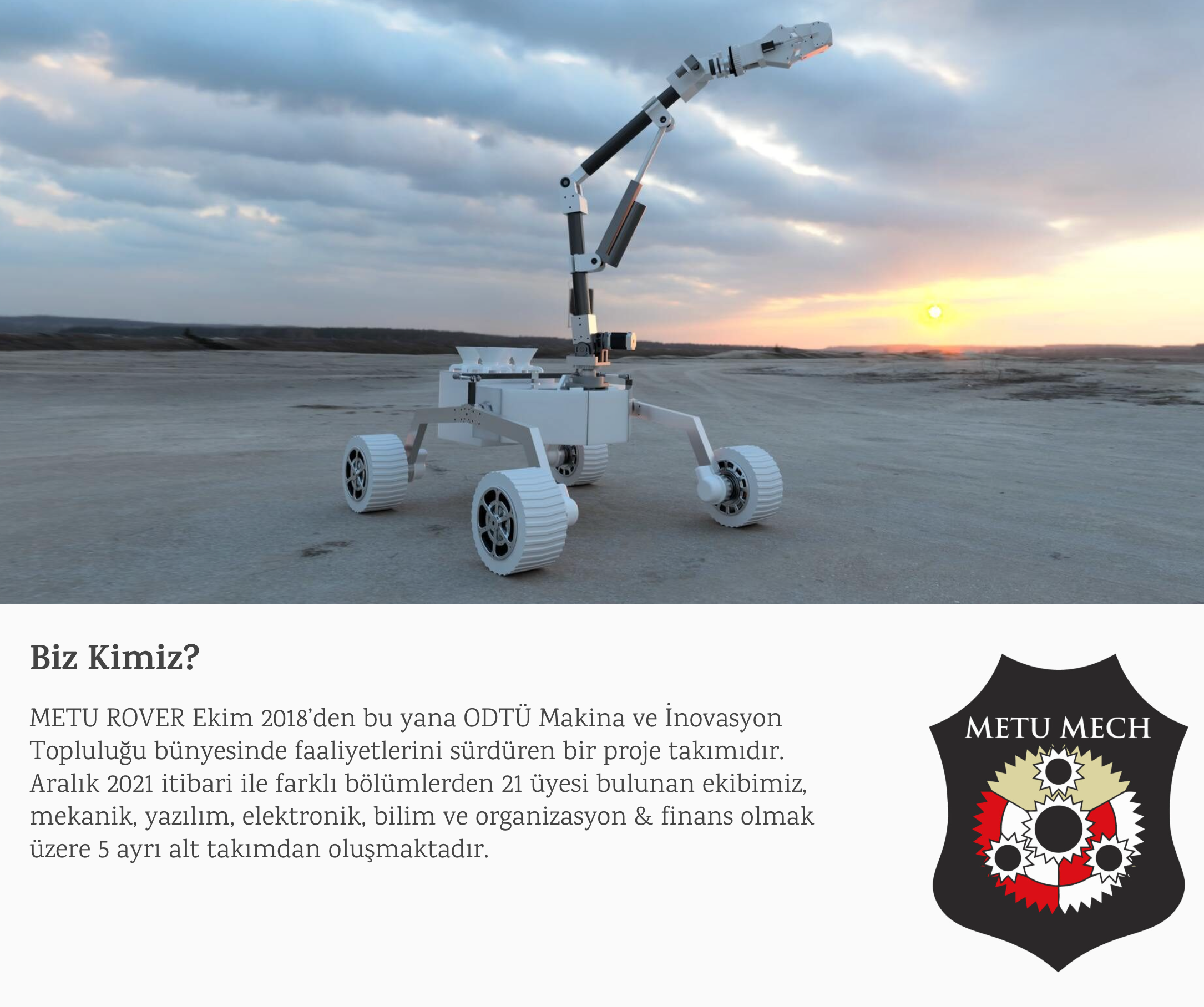
In their debut year at ERC 2020, METU ROVER placed 4th overall and received the "Best Scientists" award. The team has continued competing and growing, with applications to both ERC and URC (University Rover Challenge). For ERC 2025, the team was listed as a 41-member multidisciplinary group — one of the larger teams in the competition.
This power control module represents the kind of practical, mission-critical embedded work that makes rover competitions possible. While autonomous navigation and robotic arms get the spotlight, it is the unglamorous power distribution layer that determines whether the rover can actually function on the field.
FAQ
Q1: Can I use a standard Raspberry Pi Pico (without W5500) with this project?
No. This project requires the W5500-EVB-Pico specifically, as it depends on the WIZnet Pico C SDK's Ethernet functions. A standard Pico lacks any Ethernet hardware. Alternatively, you could use a Pico with a W5500 HAT module, but you would need to verify SPI pin assignments match the SDK's configuration.
Q2: Why UDP instead of TCP for power control commands?
UDP is connectionless and lower-overhead. In a rover scenario with a dedicated internal network, there is no need for TCP's connection setup, acknowledgment, and retransmission — the ground station can simply resend if a command is missed. UDP also avoids the risk of TCP connection drops requiring re-establishment during a timed competition task.
Q3: Is the JSON parsing approach safe for production/competition use?
For this constrained use case, yes. The strstr-based parser is predictable in memory usage (no dynamic allocation) and execution time. The trade-off is that it does not validate JSON structure — malformed packets could produce unexpected behavior. In a competition setting where both endpoints are controlled by the same team, this is an acceptable trade-off.
Q4: How many relays can the W5500-EVB-Pico control simultaneously?
The RP2040 has 26 GPIO pins available. This project uses 8 GPIO pins for relays. You could expand up to the available GPIO count, limited only by current drive capability (RP2040 GPIOs can source/sink approximately 12 mA, so relay modules with optocoupler inputs are recommended).
Q5: Could this project be adapted for other WIZnet boards like W5100S-EVB-Pico?
Yes. The WIZnet Pico C SDK supports both W5500 and W5100S boards. You would change the CMake BOARD_NAME parameter and verify that SPI and reset pin configurations match your board. The application-level code (UDP, JSON parsing, GPIO control) would remain identical.
Q6: What happens if the Ethernet connection is lost? Do relays stay in their last state?
Yes. Since GPIOs maintain their output level until explicitly changed, all relays hold their last commanded state if communication is lost. For the pulse-mode relays (latching type), this is inherent in the hardware — they physically hold state without any signal. This is a safety-relevant behavior: losing communication does not cause an uncontrolled power state change.
Q7: Can this system support multiple UDP clients sending commands simultaneously?
The code listens on a single UDP socket. Multiple clients can send to the same IP:port, and the Pico will process commands in the order they arrive. However, there is no authentication or arbitration — the last command wins. For multi-operator scenarios, implementing a simple command sequence number or priority scheme would be advisable.
-
relay_control.c
Main source file — UDP listener, JSON parser, relay GPIO control logic
