


How Does YamBMS Merge Multiple ESS BMS Units for One Inverter Over W5500 Ethernet?
YamBMS is an ESPHome project that merges parallel BMS units into one battery for the inverter. Its two ESP32-S3 Ethernet board files both configure a W5500.

WIZnet - W5500
x 1

Ethernet controller configured in two of the project's ESP32-S3 board packages. board_ESP32-S3_WS-ETH.yaml sets type W5500 with mosi 11 / miso 12 / clk 13 / cs 14 / reset 9 / interrupt 10 at 25MHz, an
One Battery Wall, Several BMS, One Inverter Port
A hybrid solar inverter with a battery communication port expects to talk to one battery. A home energy storage system built from separate packs is several batteries, each with its own BMS, wired in parallel. YamBMS is the layer in between. It is an ESPHome configuration set published by GitHub user Sleeper85 in August 2024 under GPL-3.0, described by its author as "Yet another multi-BMS Merging Solution". ESPHome is the YAML driven firmware builder behind much of the Home Assistant hardware ecosystem: you describe a device in a config file, and it compiles and flashes the firmware for you. As of 2026-08-15 the repository carries 219 stars, 63 forks and 700 commits on main, the last tagged release is 1.6.0 from 2026-06-28, and the main branch already runs version string 1.7.0.
The merged node reads every pack, combines the values, and presents one set of numbers to the inverter over CAN or RS485 using the PYLON, SMA, Victron or LuxPower low voltage protocols. What travels on that bus is listed in the README: battery voltage and current, state of charge, state of health, requested charge and discharge voltage and current, minimum and maximum cell voltage with the cell ID for each, temperature extremes with the sensor ID for each, the battery name, and alarms and warnings. Seven BMS families are integrated (JK, JBD, Seplos, PACE, BASEN, DEYE and Ecoworthy), along with Victron SmartShunt and Junctek shunts and NEEY active balancers. The supported devices page lists 28 inverter models from 13 brands as confirmed working, and every row names the user who reported it.
Two limits are stated at the top of the README rather than buried. The packs have to be in parallel, because series-connected BMS units are outside what the merging logic does. And the BMS voltage readings have to be calibrated, because every decision below keys off minimum and maximum cell voltage.
Making a set of packs look like one battery to an inverter is a recurring shape on this site. Battery-Emulator approaches it from the salvage side, presenting a repurposed EV pack to the inverter over CAN with a W5500 for the wired link, and Pylontech-monitor reads a commercial rack over its console port with W5500 Ethernet as the stable monitoring path. YamBMS covers the case where the packs are yours and there are several of them.
What the Merged Node Actually Requests
The charge control is the part worth reading the code for. Three numbers go to the inverter every cycle: the charge voltage limit, the charge current limit and the discharge current limit, usually written CVL, CCL and DCL. YamBMS computes all three itself instead of passing through whatever one BMS says.
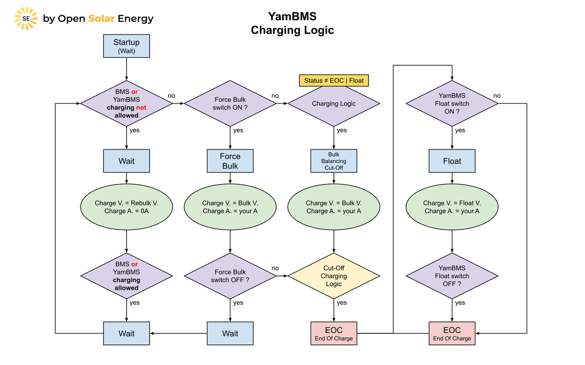
The charge current is the lowest of three values: a ceiling the user sets, the sum of the over-current protection settings of all connected BMS multiplied by 0.9, and a temperature derived limit. That third one comes from a table in the main YAML that maps cell temperature to a C rate, and it is applied to battery capacity rather than to the present current, so 280Ah at a 0.5 factor gives 140A. The default table drops the charge rate to 0.05C at 0 degrees and to zero below it, and to zero again at 60 degrees.
The end of charge behaviour is the reason the project exists. Instead of holding a fixed absorption voltage, YamBMS enters a cut-off phase whose exit condition is the cells being equalised, with a timer as a backstop. The default is a maximum of 30 minutes and a minimum of 60 seconds. Three automatic functions ride on top. Auto CVL trims the requested charge voltage when one cell starts running ahead of the bulk target, which the documentation compares to cruise control in a car. Auto CCL does the same job with current and reads the BMS over-voltage protection value, which the same page likens to a maximum speed limiter. Auto DCL mirrors it near the under-voltage limit. There is also an Auto Float mode written for a specific field problem: some inverters, the Deye SUN-12K named among them, read a sudden drop in requested charge voltage as an overvoltage and start pushing the battery into the grid, so the voltage is stepped down 0.1V at a time instead.
Two more functions come from the same practical direction. Auto EOC limits the charge current so a battery that would otherwise be full by mid-morning reaches full at a target hour instead. Auto SoC Limit stops at a chosen state of charge with a configurable hysteresis, because the author notes some inverters dislike being handed 0A. Deye equipment turns up on the vendor side of this site as well, where the GE-F128 ESS exposes a W5500 for TCP/IP diagnostics inside a finished cabinet.
The Two Board Files That Put That Node on W5500
The network side of YamBMS lives entirely in the board packages. Each board file under packages/board/ declares either a wifi: block or an ethernet: block and gives it the id my_network, so everything above it stays board agnostic. There are 33 board files. Five of them declare wired Ethernet, and two of those configure a WIZnet W5500.
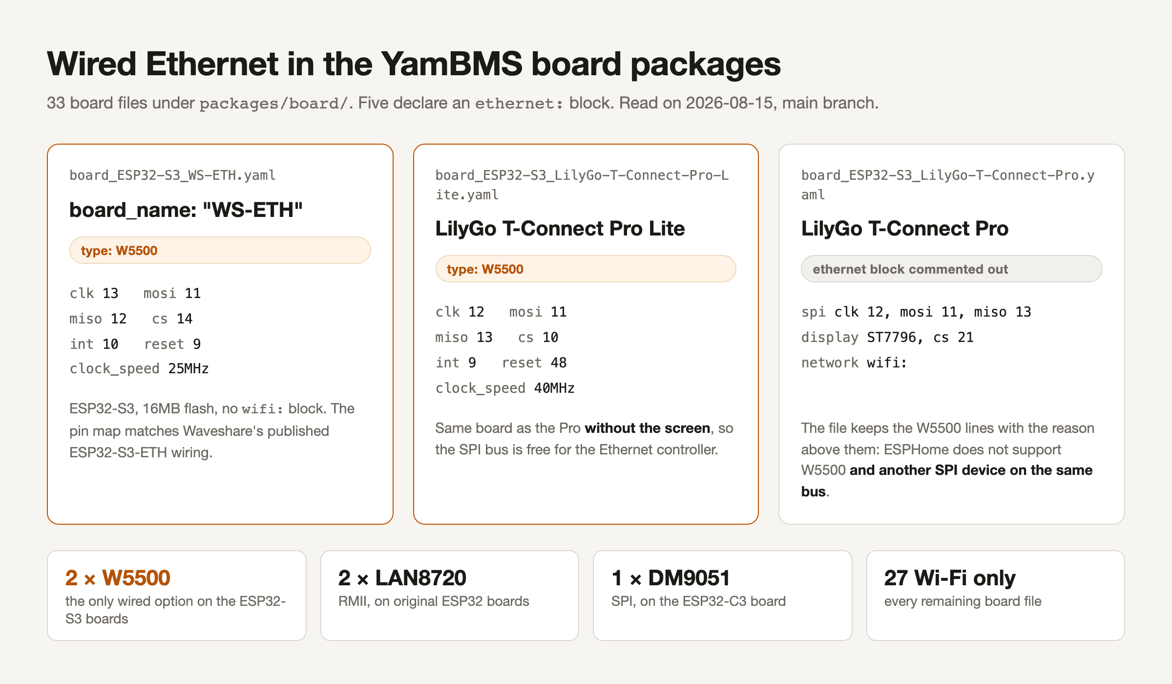
board_ESP32-S3_WS-ETH.yaml sets type: W5500 with mosi 11, miso 12, clk 13, cs 14, reset 9, interrupt 10 and clock_speed: 25MHz. Those six pins match the wiring Waveshare publishes for its ESP32-S3-ETH board, which the vendor wiki describes as an ESP32-S3R8 with an onboard W5500 giving 10/100Mbps over SPI and support for an external PoE module. board_ESP32-S3_LilyGo-T-Connect-Pro-Lite.yaml sets the same type: W5500 with clk 12, mosi 11, miso 13, cs 10, interrupt 9, reset 48 and clock_speed: 40MHz.
The other three wired boards use different silicon, which matters if you go shopping from this repository. The ESP32-C3 ETH01-EVO is a Davicom DM9051, and the WT32-ETH01 and the Olimex ESP32-EVB use the ESP32 RMII path with a LAN8720. So the two W5500 files are the only wired Ethernet option among the ESP32-S3 boards, and the ESP32-S3 with PSRAM is exactly what the project recommends when you are merging several BMS, balancers and shunts at once.
Underneath, ESPHome drives the chip as a MAC and PHY rather than as a TCP/IP offload engine. The component pulls in the ESP-IDF headers esp_eth_mac_w5500.h and esp_eth_phy_w5500.h, registers an esp_netif interface and lets lwIP handle the sockets. ESPHome also ships a W5500 specific SPI driver whose comment states its purpose plainly: transfers larger than the 64 byte hardware FIFO, meaning the frame payloads, go through the blocking DMA path so the calling task sleeps, while small register accesses stay on the cheaper polling path. That file is present in ESPHome 2026.6.0, which is the minimum version YamBMS asks for.
The Screen or the Ethernet Port
The most useful piece of hardware advice in this repository is a constraint, and it is written into a board file as a comment. board_ESP32-S3_LilyGo-T-Connect-Pro.yaml contains a complete W5500 block, commented out, with the reason above it: ESPHome does not support a W5500 and another SPI device on the same SPI bus. LilyGo's own description of the T-Connect Pro explains why that bites on this board: the stack carries an ST7796 LCD, an SX1262 LoRa module and the W5500, and all three are SPI devices. You can see the collision in the file itself, where the active spi: bus for the display declares clk 12, mosi 11 and miso 13, the same three pins the commented W5500 block asks for. The board file therefore ships with the display active and wifi: as the network.
That is not a dead end in the repository, it is the origin of a board. When the T-Connect Pro support was first proposed in April 2025, the contributor listed "Ethernet instead of display" as a planned alternative configuration and gave the same reason. In March 2026 another user opened a board file for the T-Connect Pro Lite, the same hardware without the screen, and said so in one line: Ethernet support was added because the SPI bus is no longer needed for the display. He reported running it with EG4 batteries and a Sol-Ark inverter. That file was merged and now sits in the repository as the second W5500 entry.
One RS485 Bus, Many Nodes
A single ESP32 can only reach so many packs. The documented ceilings are three BLE devices on an ESP32-S3, three UART BMS, and several RS485 BMS on one bus. Past that, YamBMS splits into nodes. Each BMS, shunt or balancer node becomes a Modbus server with its own address on a dedicated RS485 bus, and node 1 runs YamBMS as the Modbus client, combines everything, and holds the CAN link to the inverter. The theoretical ceiling is 256 Modbus servers per bus, and the author is careful to say the real ceiling is whatever node 1 can process.
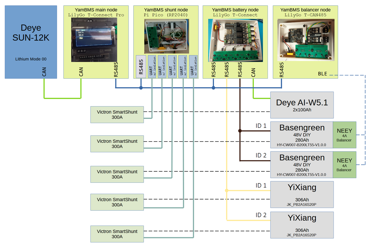
That example is worth reading closely because it shows how mixed a real system is. One RS485 Modbus bus carries four nodes. The main node holds CAN to a Deye SUN-12K in Lithium Mode 00 plus its own RS485 leg. A Raspberry Pi Pico node handles five Victron SmartShunts over isolated UART. A battery node holds a CAN leg to a Deye AI-W5.1 plus RS485 legs to two Basengreen 280Ah packs and two YiXiang 306Ah packs. A balancer node reaches two NEEY balancers over BLE. Every one of those links is a field bus or a short range radio, and none of them is the uplink.
What the Wire Carries, and What Tells You It Dropped
On a W5500 board the Ethernet link is the only path off the device. ESPHome states that its ethernet and wifi components may not be used at the same time even when both are physically available, so these two board files are wired only nodes by construction. What runs over the link is the Home Assistant API, over the air updates, the optional web server, optional MQTT, and an opt-in statistics report that the README documents field by field, including the fact that only the author can read it. The README also notes what those reports added up to: 160 YamBMS users in January 2026.
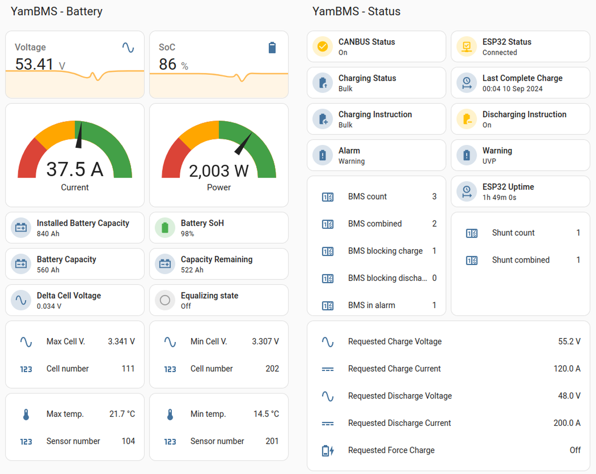
The wired boards also get link supervision written into the shared Ethernet package. An ethernet_info text sensor publishes the IP, DNS and MAC addresses of the W5500 interface, and a five second interval calls network::is_connected() and pushes the result into the project's fault registry. That registry drives a blink code on the board LED, and network is category 7: seven red pips after a blue header blink means no Ethernet or Wi-Fi link. It is a small thing, and it means an ESS cabinet with no screen still tells you which subsystem dropped.
What This Repository Does Not Publish
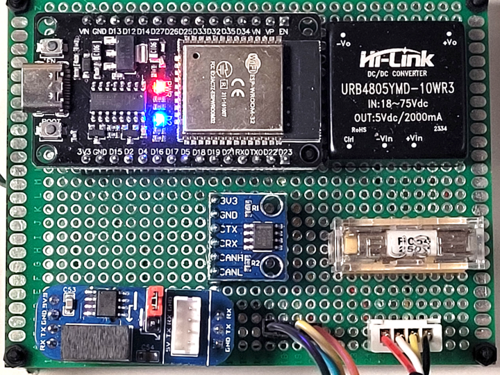
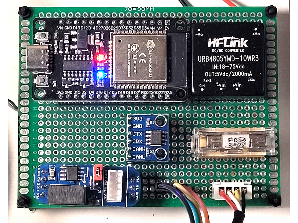
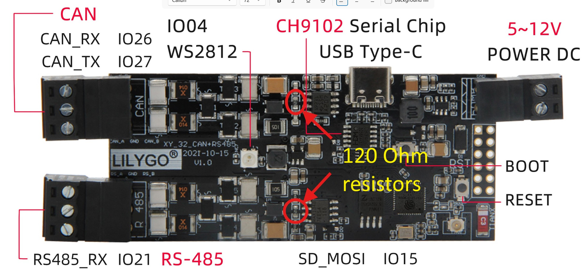
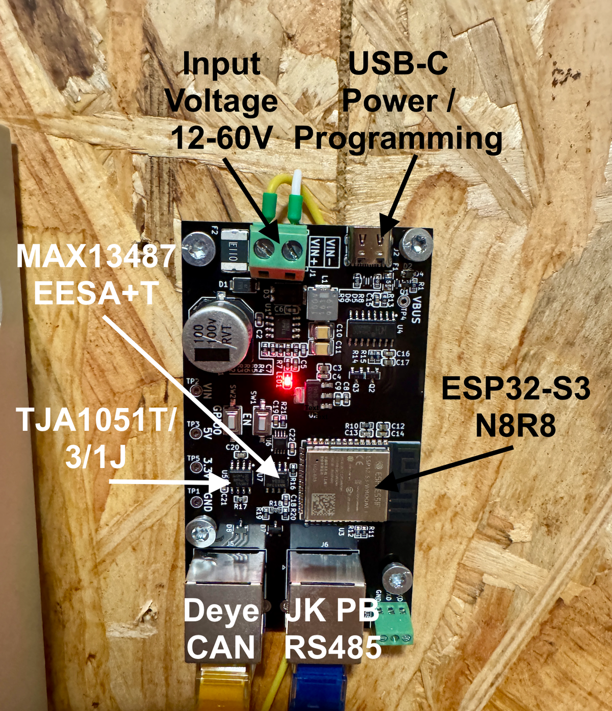
The W5500 boards here are off-the-shelf vendor hardware, so the repository publishes the pin maps in YAML and nothing else. There is no schematic, no PCB file and no bill of materials for either W5500 board, and the images folder has no photograph of either one. The custom boards that do appear in the photographs, including the one above, are Wi-Fi boards in their published configurations.
Nothing about the wired path is measured. There are no throughput, latency or packet loss figures for the Ethernet link, and no comparison against the Wi-Fi boards. Power over Ethernet is claimed for the ETH01-EVO in the project documentation and for the Waveshare board on the vendor's own wiki, but the repository does not document a PoE setup of its own. No prices appear anywhere in the repository. The ESPHome discussion linked next to the commented out W5500 block no longer resolves, so the constraint stands on the board file comment, the contributor's own note, and LilyGo's shared bus description rather than on that link. And the DIY Solar Forum thread the README points to for discussion blocks automated fetches, so the community reading here comes from the issue tracker and pull requests instead.
One more boundary is worth stating plainly, because the repository has five Ethernet boards and only two of them are WIZnet. If you pick the ETH01-EVO or the WT32-ETH01 from the supported list you are not running a W5500.
FAQ
Q. Does YamBMS need Home Assistant? No. The Home Assistant API is one option in the entry YAML, and the file offers MQTT or the built-in web server instead, or nothing at all. The inverter link over CAN or RS485 does not depend on any of them.
Q. Which boards give me the wired option with a W5500? Two board packages: board_ESP32-S3_WS-ETH.yaml, whose pin map matches the Waveshare ESP32-S3-ETH, and board_ESP32-S3_LilyGo-T-Connect-Pro-Lite.yaml. The dedicated YamBMS_RP_Ethernet_board.yaml entry file lists the Waveshare one as a commented alternative to its default.
Q. Can a W5500 board fall back to Wi-Fi if the cable is unplugged? Not in this design. ESPHome's own documentation states the ethernet and wifi components may not be used simultaneously, and neither W5500 board file declares a wifi: block.
Q. Is the W5500 acting as a TCP offload engine here? No. ESPHome binds it through the ESP-IDF esp_eth W5500 MAC and PHY drivers and runs the TCP/IP stack in lwIP on the ESP32-S3, so the chip is doing Ethernet frames over SPI rather than sockets in hardware.
Q. Does it work with battery packs wired in series? No. The README states in bold that merging works for parallel-connected BMS units only.
-
YamBMS repository
The ESPHome package set, its documentation folder, and the board packages. GPL-3.0

-
YamBMS_RP_Ethernet_board.yaml
The entry YAML for wired builds. Lists the W5500 Waveshare board as one of its three Ethernet board options
-
board_ESP32-S3_WS-ETH.yaml
First W5500 board package: full SPI pin map and 25MHz clock, no wifi block
-
board_ESP32-S3_LilyGo-T-Connect-Pro-Lite.yaml
Second W5500 board package, contributed in March 2026 for the screenless variant, 40MHz clock
-
board_ESP32-S3_LilyGo-T-Connect-Pro.yaml
Same board with a screen. The W5500 block is kept commented out with the shared SPI bus constraint written above it
-
YamBMS charging logic
Charging state machine, cut-off equations and the per chemistry CV min and CV max values
-
YamBMS supported devices
BMS, shunt, balancer and transceiver support, plus 28 inverter models reported working by named users
-
ESPHome Ethernet Component
States W5500 support on ESP32, the clock_speed rules, and that the ethernet and wifi components may not be used at the same time
-
Waveshare ESP32-S3-ETH wiki
Vendor documentation for the board whose W5500 wiring matches the WS-ETH package, including the external PoE module option
-
WIZnet W5500
The Ethernet controller used on both wired ESP32-S3 board options


