


How Does an ESP32-S3 Modbus Gateway Serve Field Points as MCP Tools over W5500 Ethernet?
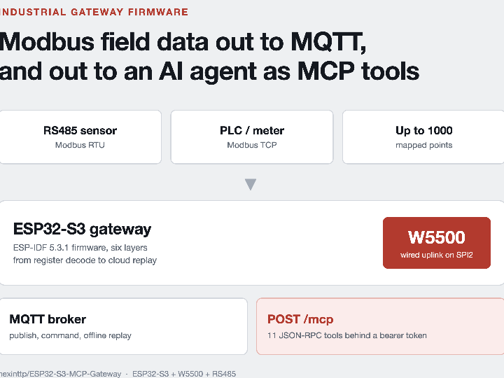
hexinttp's ESP-IDF firmware maps Modbus RTU and TCP registers to named points, publishes them over MQTT, and serves 11 MCP tools, with W5500 as default route.

WIZnet - W5500
x 1

SPI2 Ethernet uplink at 20 MHz, CS GPIO10 / MOSI 11 / SCLK 12 / MISO 13 / INT 14, default route with route_prio 150
📌 An Industrial Gateway That Also Answers as an MCP Server
A developer publishing as hexinttp opened the ESP32-S3-MCP-Gateway repository on 14 July 2026 and closed the current revision on 14 August 2026, fifteen commits later. It is ESP-IDF 5.3.1 firmware for an ESP32-S3 board that polls industrial Modbus devices over RS485 and Ethernet, publishes the readings to an MQTT broker, and answers Model Context Protocol (MCP) JSON-RPC calls at POST /mcp, so an AI assistant can list, read and (only when an operator turns it on) write those same points. The wired path is a WIZnet W5500 on SPI2, and the firmware makes it the default route while the cable is live.
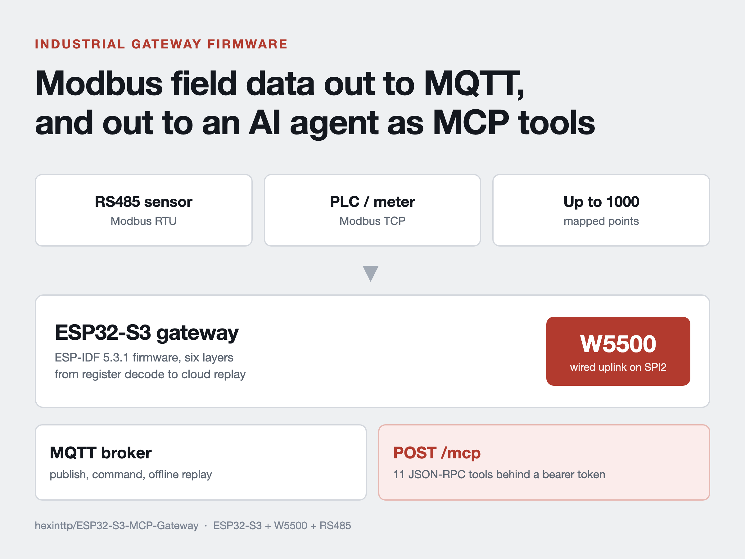
Two terms carry the story. Modbus is the plain register protocol most factory sensors, meters and PLCs still speak: ask a device for word 40001 and it returns sixteen bits with no name, unit or scale attached. MCP is how an AI client calls a tool, asking a server for its tool list and then calling one by name with typed arguments. This firmware sits between the two.
The author stays private, with no name, company, location or contact on the GitHub profile. The surrounding material still says something. The README is written against numbered research objectives and the deployment checklist refers to a "thesis bench network", so this reads as an academic project rather than a product. A second repository on the same account, modbus_device_simulator, turns a PC into the Modbus slaves used in the gateway's own bench tests, with twenty device profiles the author says came from vendor manuals. The gateway README mentions a "PC RTU simulator" without linking it, so the pair only becomes visible from the profile.
Six Layers From an RS485 Register to a Cloud Payload
The README organises the firmware into six layers, and the main/ tree follows them closely.
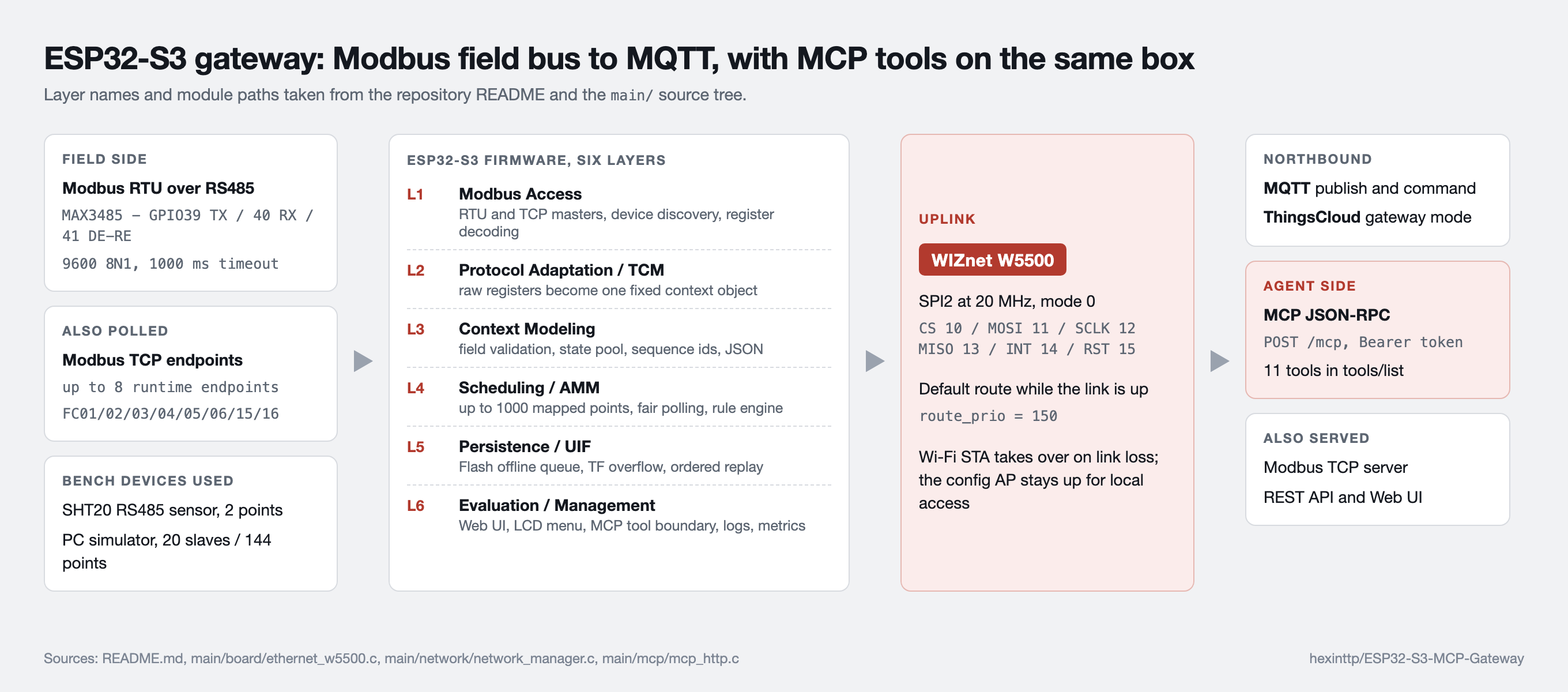
L1 talks to the field: an RS485 Modbus RTU master through a MAX3485 transceiver on GPIO39/40/41 at 9600 8N1, plus up to eight runtime Modbus TCP endpoints, covering function codes 01 through 06, 15 and 16. L2 and L3 turn the replies into one fixed JSON object the author calls a TCM context, carrying protocol, channel, slave id, register, data type, byte order, raw value, scale, unit, quality and a power-safe sequence number. L4 is the mapping model, up to 1000 points held in PSRAM with a fair polling order that serves the least recently polled point first. L5 is the offline path: when the broker is unreachable, records go to a 13 MB queue in SPI flash, spill to the TF card when that fills, and replay in sequence once the session recovers. L6 is what a human or an agent touches: the Web UI, the LCD status pages, the logs and the MCP tool boundary.
⚙️ The W5500 Is the Preferred Uplink, Wi-Fi Is the Fallback
main/board/ethernet_w5500.c brings the chip up by hand rather than through a board support layer. It initialises SPI2 with spi_bus_initialize(), configures the device at 20 MHz in SPI mode 0, then builds the driver with ETH_W5500_DEFAULT_CONFIG, esp_eth_mac_new_w5500(), esp_eth_phy_new_w5500() and esp_eth_driver_install(). Pin numbers live as macros in main/board/board_pins.h and match the README wiring table, including the detail that GPIO15 is a reset line shared with the on-board ST7735S LCD and driven by the board module for both. In sdkconfig, CONFIG_ETH_SPI_ETHERNET_W5500=y is the only SPI Ethernet driver enabled.
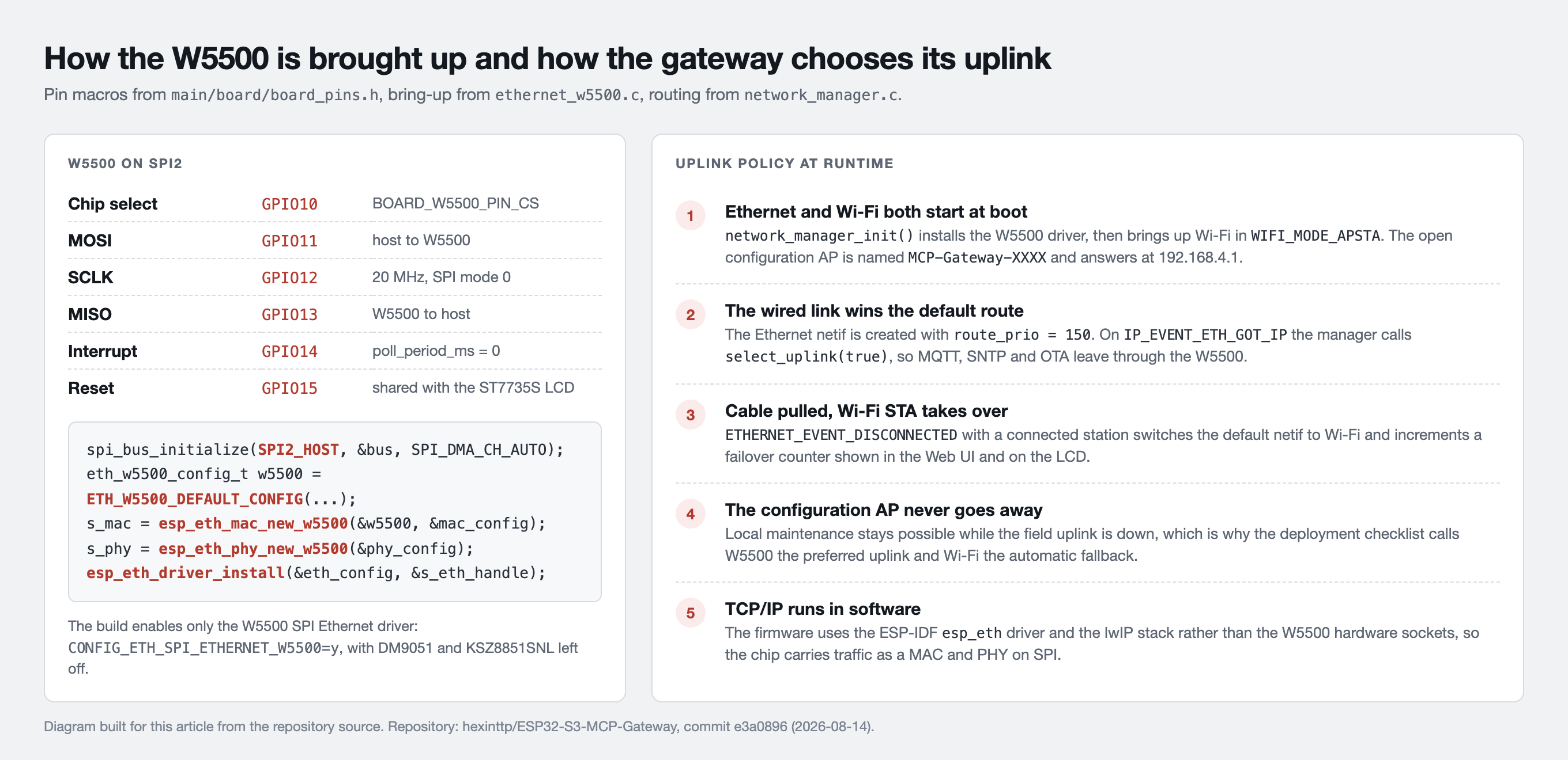
main/network/network_manager.c is what makes this more than a bring-up example. Both networks start in the same function: the W5500 driver first, then Wi-Fi in WIFI_MODE_APSTA, which raises a station interface and an open configuration access point named MCP-Gateway-XXXX at 192.168.4.1. The Ethernet interface is created with route_prio = 150, so on IP_EVENT_ETH_GOT_IP the manager calls select_uplink(true) and MQTT, SNTP and OTA traffic leaves through the wired port. Pull the cable and ETHERNET_EVENT_DISCONNECTED moves the default interface to the Wi-Fi station, incrementing a failover counter shown in the Web UI and on the LCD. The two uplinks are therefore a preference with a fallback, not two links sharing traffic. The access point is the part that runs in parallel: maintenance stays reachable over Wi-Fi while field data leaves over Ethernet. The deployment checklist puts it plainly: "W5500 is the preferred uplink." TCP and UDP themselves are handled by lwIP, with the W5500 acting as the SPI MAC and PHY.
Reading the Gateway Through Its Own Web UI
The repository ships no photographs. There is not a single image file in it, no board shot, no enclosure, no schematic and no scope trace, so nothing here shows the physical device. What it does ship is web/web_config.html, a 210 KB single-file management page, plus Python scripts that emulate the REST API and a Modbus bus on a PC. The captures below come from running those scripts locally and rendering that page in a browser, so the counters are simulator values, not measurements from a board.
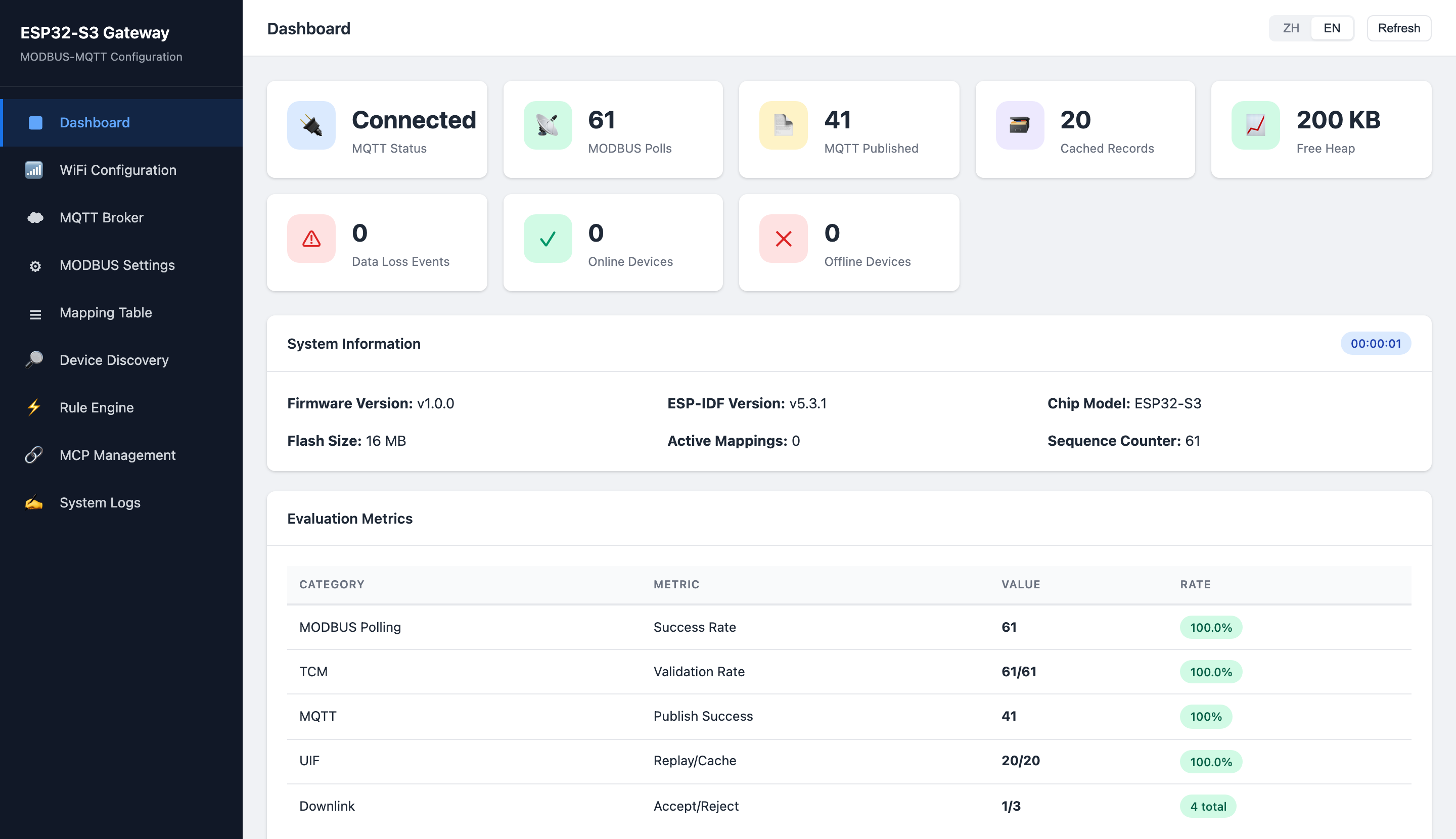
The dashboard is where the research framing shows through. Alongside connection state and free heap it reports polling success, TCM validation rate, MQTT publish success, offline replay against cache, and accepted versus rejected downlink commands. On hardware the same figures come from /api/system/status.
Turning Raw Registers Into Named Engineering Points
The mapping table is the heart of the firmware. Each row binds a protocol, channel, slave id and register address to a device id, point id, data type, byte order, scale, offset, unit, writable flag and value range, then to the MQTT topic it publishes on.
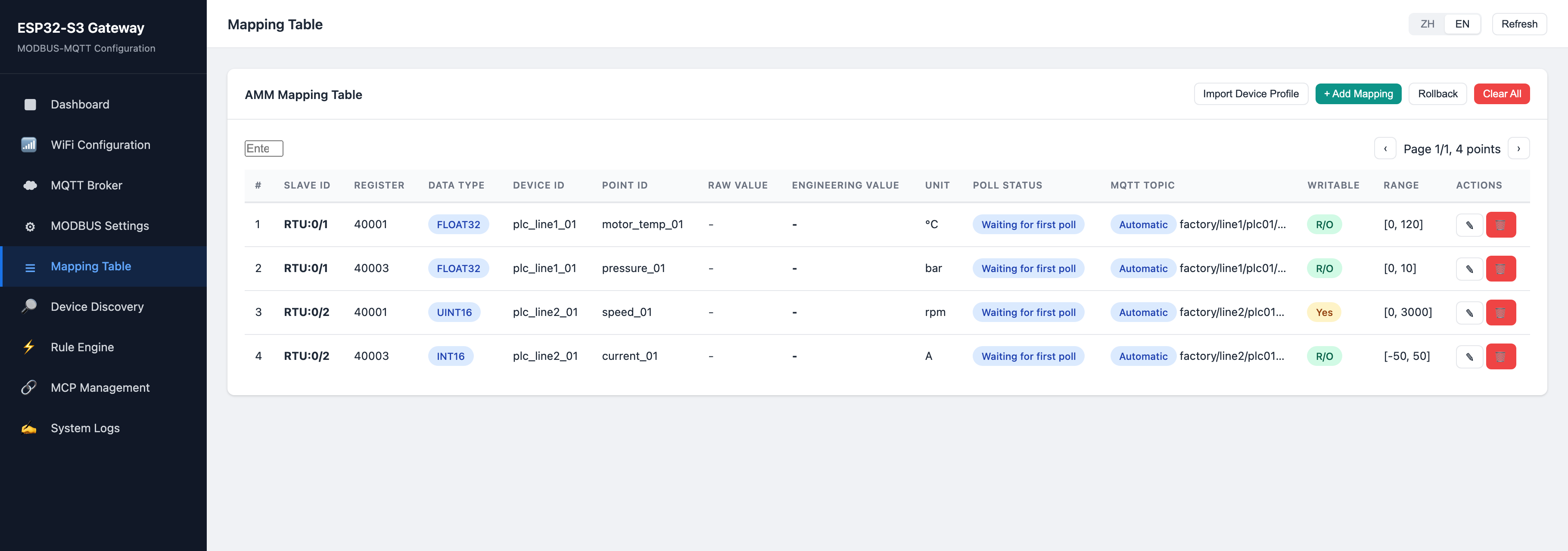
Where the points come from is the interesting part. Device discovery scans a slave range in two phases: a cheap online probe first, then a register scan only for slaves still answering when the second phase starts, and the whole pass is read only. Anything found without a matching profile becomes a read-only point marked DISCOVERY / UNRESOLVED, keeping a stable device fingerprint and the response evidence, and the firmware refuses to guess unit, scale, sign or multi-register layout. An operator then imports a device profile or edits the row, promoting it to USER / VERIFIED, after which the engineering value is decoded_raw_value * scale_factor + offset.
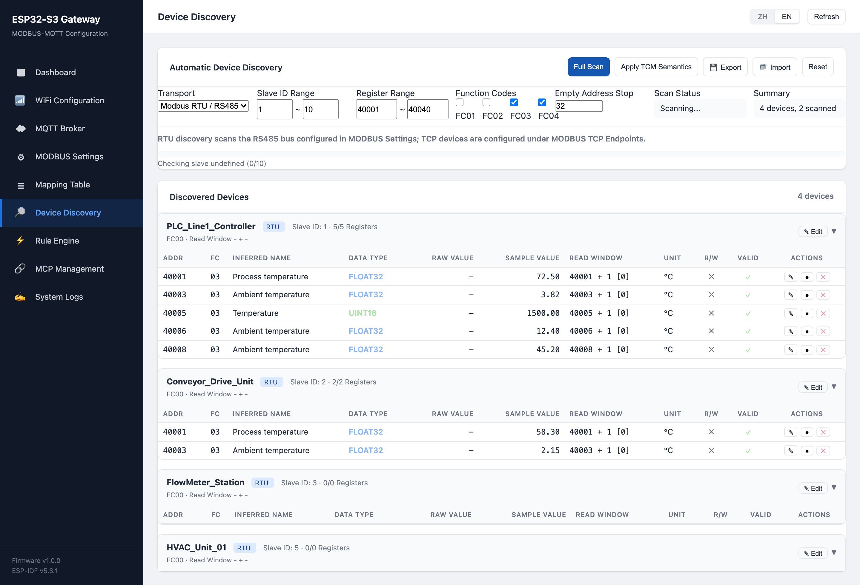
That refusal to guess is the design choice worth borrowing, because an invented unit travels all the way to the dashboard and looks just as trustworthy as a correct one.
Eleven MCP Tools, All Behind a Bearer Token
main/mcp/mcp_http.c implements a small MCP server directly in firmware: initialize answers with protocol version 2025-03-26 and a server name, tools/list returns the catalogue, tools/call dispatches. The catalogue holds eleven tools: list_points, read_point, write_point, discover_modbus_devices, get_gateway_config, get_cache_status, list_rules, rule_preview, rule_commit, rule_delete and export_logs. The README table and the Web UI page still list the eight that existed before the final commit, so the code is the accurate source.
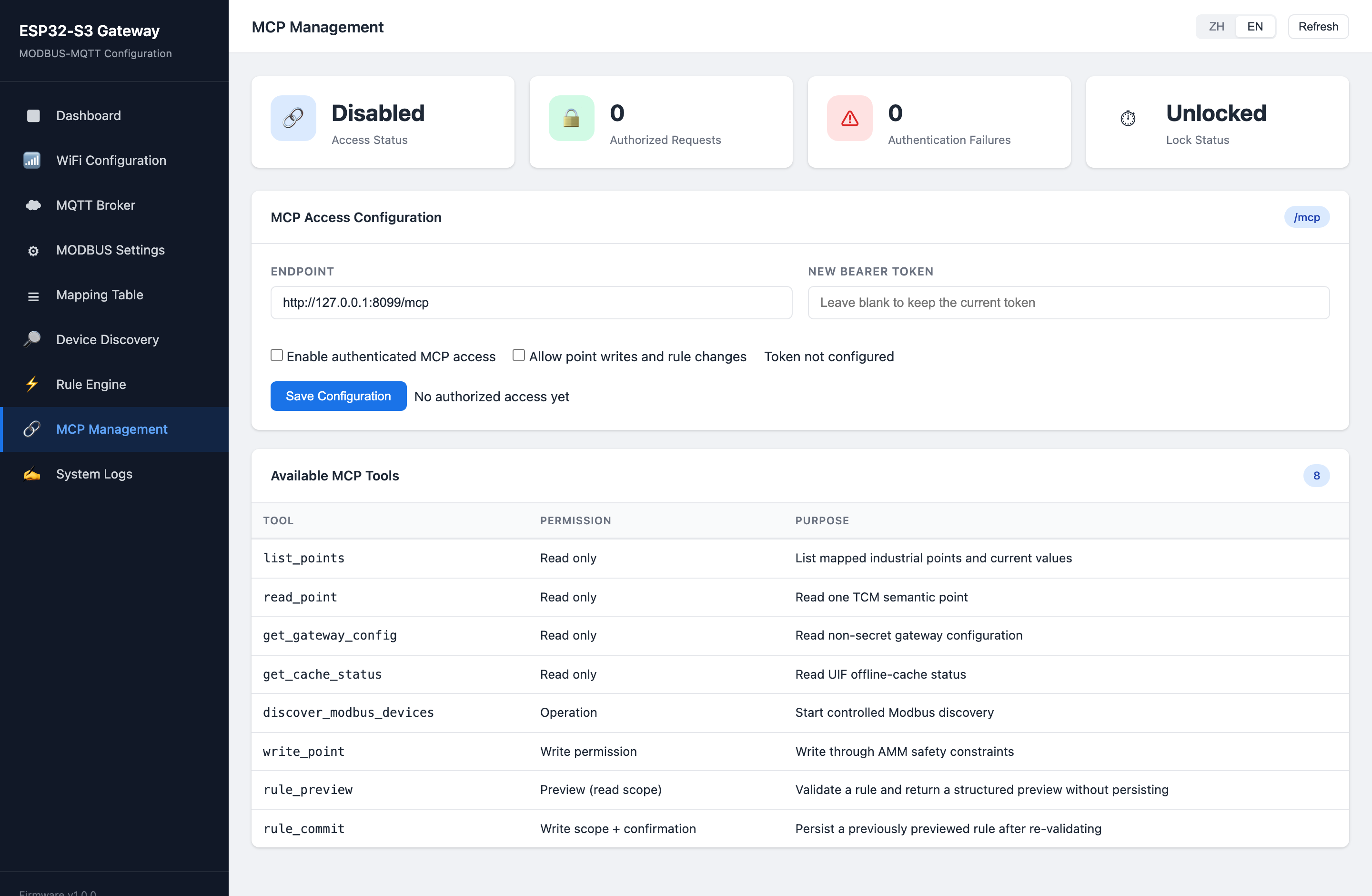
The access rules are stricter than the tool count suggests. MCP is refused until authentication is configured, so a fresh board answers /mcp with 403. Every request must carry Authorization: Bearer <token>, tokens are stored only as SHA-256 digests in a dedicated NVS namespace, and each token carries a read, write or admin scope. Failed authentication locks out the offending IP address for thirty seconds and only that address, which the source comments describe as fixing an earlier global counter that let one client lock out everyone. write_point and rule_commit need write scope, and both also need mcp_write_enabled, which ships off.
Rule configuration shows the agent-safety thinking most clearly. The client turns a natural-language instruction into the rule schema and must call rule_preview first. The gateway validates the source point, optional interlock, writable target, value range, hysteresis and a cooldown of at least 200 ms, then returns a normalised preview without changing anything. Only after the user confirms may the client call rule_commit, which re-validates every boundary before writing. The README is candid about the ceiling: for deployments needing full MCP sessions, auditing and multi-client governance, it suggests running a real MCP server on an edge computer that calls this firmware's controlled interface instead.
Where This Sits Next to Other MCP Work on This Site
Three neighbouring posts make the differences easy to see. BREMA puts an MCP server on a KNX USB stick so an agent can commission building devices, which is a commissioning tool for an installer. mcpd is a reusable MCP server SDK for microcontrollers that reaches its client through a host bridge and states that its Ethernet runtime is unfinished. This project is a third shape: a working industrial gateway that already had a job, with an MCP endpoint added to the same firmware and reached over its own wired interface. bruno's offline cache gateway overlaps on another axis, since both argue that broker-side QoS alone does not save data across an outage, and both answer with a local queue and ordered replay.
What Is Verified, and What Is Not
The README lists what ran on hardware: build and flash on an ESP32-S3 with 16 MB flash and 8 MB PSRAM under ESP-IDF 5.3.1, W5500 SPI driver initialisation through DHCP, RS485 half duplex on GPIO39/40/41, a real SHT20 sensor read at slave 1 with FC04, 146 RTU engineering points polling from the lab profile with 1045 consecutive successful polls, and a ThingsCloud session reporting 146 aggregated attributes in a ninety second window. It is equally clear about the gaps: the hundred-device stress test has not been run, the 1000-point figure is allocation capacity and not a refresh guarantee, TF card endurance still needs testing, and a known issue records that writes into the flash offline queue fail intermittently during an MQTT outage. The Web configuration UI has no login by default and the author says so. There is no LICENSE file, so reuse terms are not stated, and with no stars, forks, issues or releases there is no outside feedback to read yet.
❓ FAQ
Q. What does this project use the W5500 for? It is the gateway's wired uplink, driven over SPI2 at 20 MHz through the ESP-IDF esp_eth W5500 driver. Once it has a DHCP address it becomes the default route, so MQTT, SNTP and OTA all leave through it.
Q. Does the gateway still work if the Ethernet cable is unplugged? Yes. Wi-Fi station mode is brought up at the same time and takes the default route when the link drops, with a failover counter recording each switch. The configuration access point stays available throughout for local maintenance.
Q. Can an AI agent change industrial outputs through this firmware? Only under several conditions at once: MCP access enabled with a bearer token issued, the token holding write scope, mcp_write_enabled turned on, the target point marked writable, and the value inside the range stored in the mapping entry.
Q. What happens to data while the MQTT broker is unreachable? Records go to a queue in SPI flash, with the TF card as overflow, and replay in sequence once the connection returns, deleted only after the broker acknowledges. The author lists intermittent queue-write failures on this path as an open issue.
Q. How much of this can be reused on another board? The Ethernet, network, Modbus, mapping and MCP modules are ordinary ESP-IDF C with pin choices isolated in one header, so retargeting another ESP32-S3 board is mostly a pin edit. No licence file is published, so reuse terms should be confirmed with the author first.
-
ESP32-S3-MCP-Gateway repository
Full ESP-IDF 5.3.1 firmware source for the Modbus to MQTT gateway with the MCP endpoint

-
README with GPIO map and verification status
Six-layer architecture, W5500 and RS485 wiring table, flash partitions, and the author's hardware test results
-
ethernet_w5500.c
W5500 bring-up: SPI2 bus init, ETH_W5500_DEFAULT_CONFIG, MAC and PHY creation, driver install, netif route priority
-
board_pins.h
Pin macros for the W5500 SPI lines, the shared reset with the ST7735S LCD, the TF card and the RS485 transceiver
-
network_manager.c
Wired-first uplink selection, Wi-Fi APSTA bring-up, failover counting on Ethernet link loss
-
mcp_http.c
MCP JSON-RPC server: initialize, tools/list with eleven tools, bearer token scopes, per-IP lockout, preview and commit for rules
-
Industrial deployment checklist
RS485 isolation, Ethernet protection, storage and OTA notes, and the statement that W5500 is the preferred uplink
-
web_config.html
The 210 KB single-file management UI rendered for the screenshots in this article
-
modbus_device_simulator by the same author
PC-side Modbus RTU and TCP slave simulator with twenty vendor-manual device profiles, used for the gateway bench tests


