


How Does a Wires-First UART Combiner Move Four Serial Streams Over W55RP20 Ethernet?
An open KiCad board merges four serial lines into one Ethernet feed on a W55RP20, driving ioLibrary hardware sockets directly with no lwIP in the build.
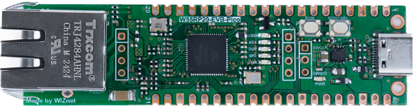
WIZnet - W55RP20-EVB-Pico
x 1

The only active module on the gateway board. gateway.kicad_pcb places footprint Module:WizNet_W55RP20_EVB_Pico with the WizNet_W55RP20_EVB_Pico.step model, and the firmware builds with BOARD_NAME W55R
A Home Automation Project That Rules Out Radio First
pcb-wires-first is a set of open KiCad boards published by devbotas, a GitHub account that carries 20 public repositories. Commits are authored as Simonas from a simon@devbot.lt address, 70 of the 71 commits across the hardware and firmware repositories behind this project, the one exception being an edit made through the GitHub web interface.
Most of the account's older repositories are C#, and several of the names point at Lithuania. One is a Homie Modbus to MQTT translator for the Domekt200 recuperator built by Komfovent, three carry the namespace of Light Conversion, whose own site titles itself "Light Conversion | Femtosecond Lasers", and another is described by its author as a "Control hub for my engineering shed (all the heaters, recuperators, solar inverters sit there)".
GitHub sums the repository up in five words, "A wires-first home automation controllers", and the README states the premise before any board appears. "Wireless IoT sucks," it opens, then gives the fix: "Put the analog wires first! So that light switches continue to operate even if smart features decide to stop working."
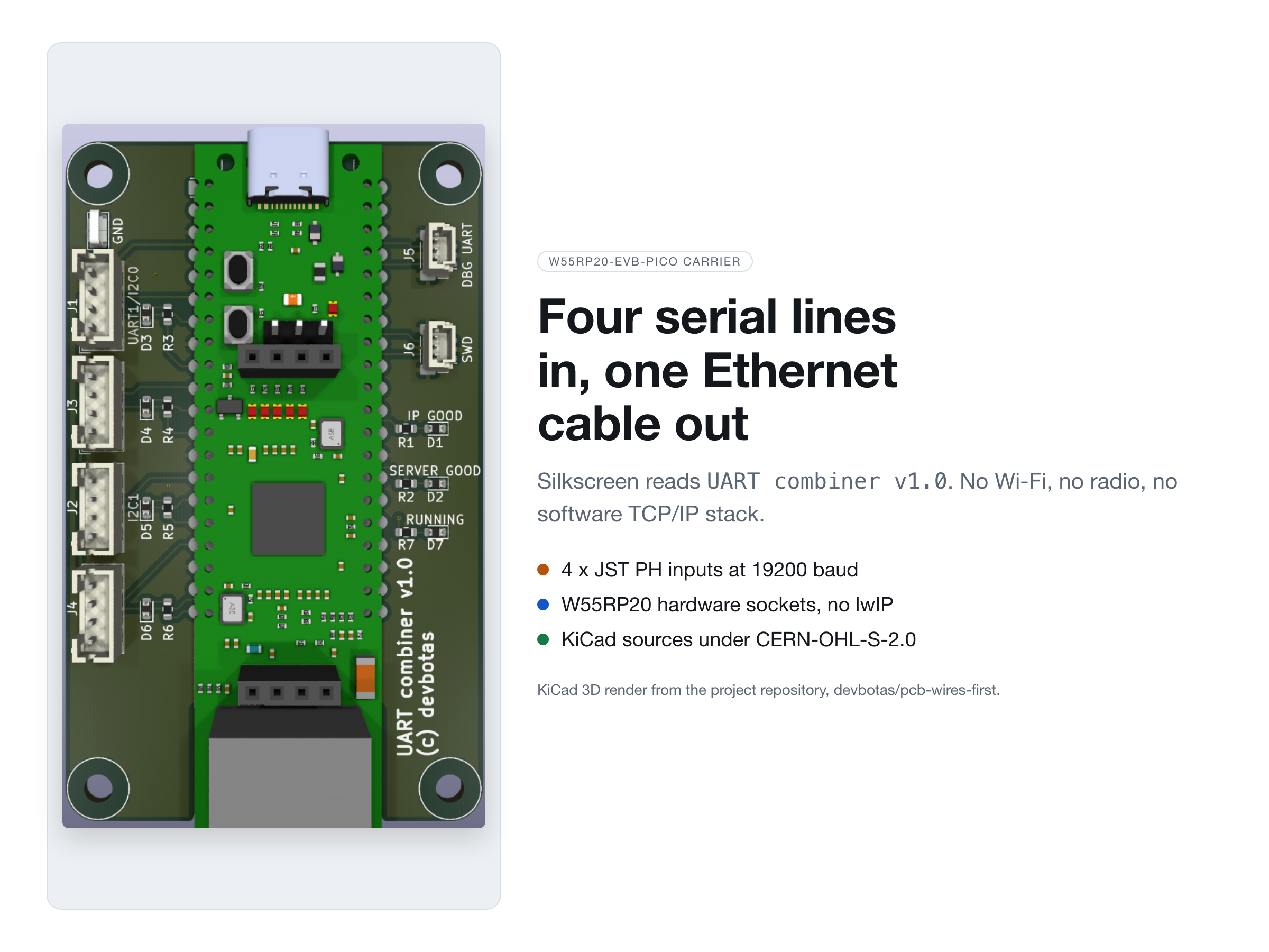
One of the four board types in that repository carries a WIZnet part, and the README introduces it in a line: "This is a simple carrier board for WizNET W55RP20 development module." That is accurate and also modest, because the board and the firmware written for it add up to a four-channel serial to Ethernet combiner with no radio anywhere in the design.
The Silkscreen Still Calls It a UART Combiner
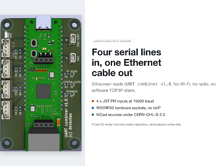
The gateway board joined the repository on 2026-07-27 in a commit titled "Adding gateway project", but the front silkscreen carries an older name. pcb/gateway/gateway.kicad_pcb holds exactly one free text object on the F.SilkS layer, reading UART combiner v1.0 (c) devbotas, and the KiCad project file kept the same older name inside itself: until commit 2141c927 on 2026-08-18, gateway.kicad_pro still recorded its own filename as uart-combiner.kicad_pro and its root sheet as uart-combiner.kicad_sch.
The parts list backs the older name up. The board places 27 footprints on a 47.4 by 77.4 mm outline: one Module:WizNet_W55RP20_EVB_Pico footprint with the matching WizNet_W55RP20_EVB_Pico.step model, four vertical JST PH 1x04 connectors, two JST SH 1x03 connectors marked SWD and DBG UART, seven 0603 LEDs with seven 2.2k resistors, four M3 mounting holes, a ground test point and one solder jumper.
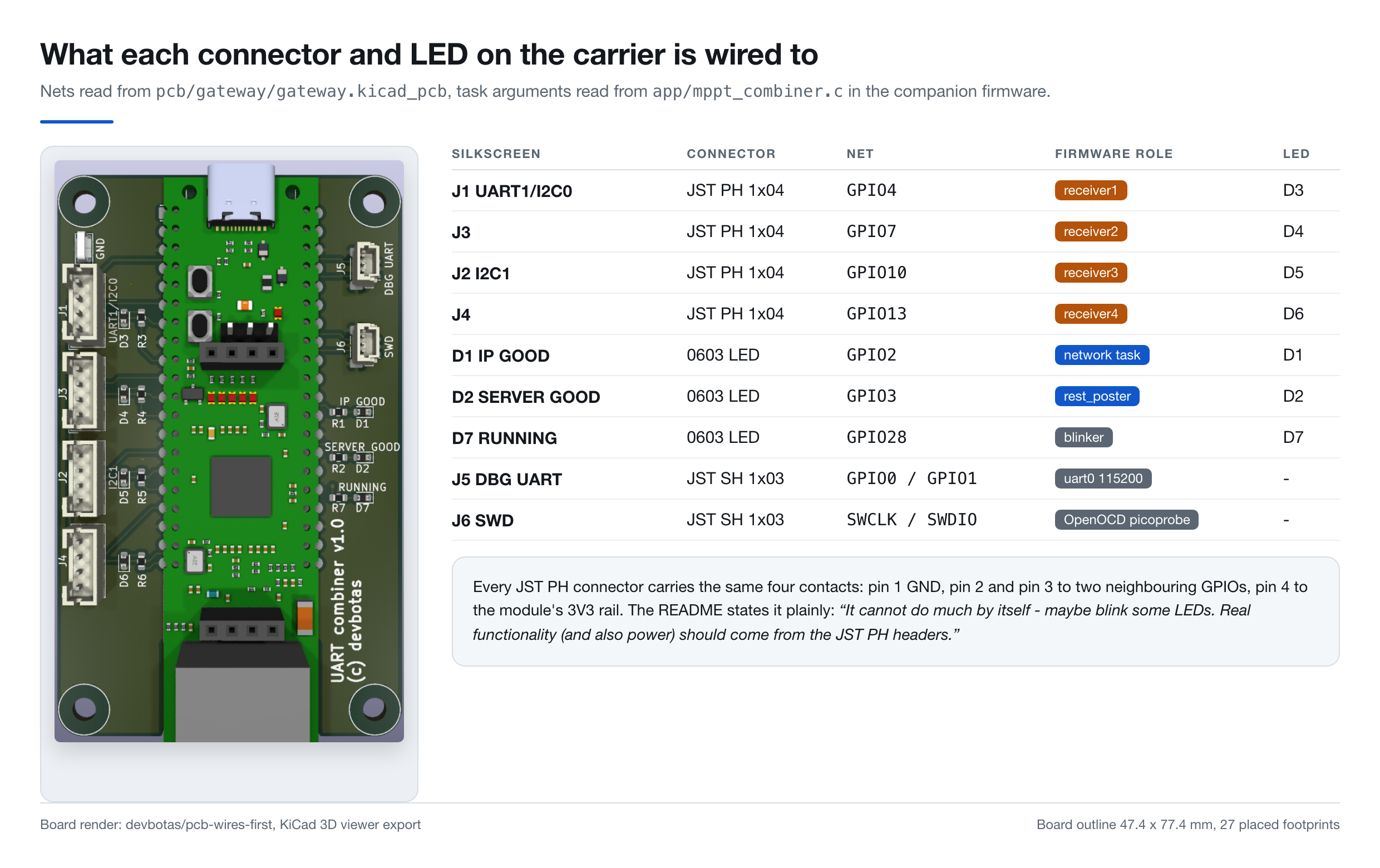
Each JST PH connector is wired identically: ground on pin 1, two neighbouring GPIOs on pins 2 and 3, and the module's 3V3 rail on pin 4. That symmetry is why the README warns that "It cannot do much by itself - maybe blink some LEDs. Real functionality (and also power) should come from the JST PH headers."
The two smaller JST SH connectors serve the bench rather than the field. J5 carries GPIO0 and GPIO1 for the debug console that app/mppt_combiner.c opens with initialize_uart0_for_debug_output(115200), and J6 carries SWCLK and SWDIO for the picoprobe adapter named in openocd-rp2040-cmsis-dap.cfg.
Four Solar Chargers, Four PIO State Machines
A second repository, fw-victron-mppt-combiner, gives the gateway board its job. Created 2026-08-05 and last pushed 2026-08-11, it describes itself as software that "Combines multiple Victron SmartSolar/BlueSolar MPPTs and mimicks them over ethernet", and names its hardware plainly: "At it's heart there's a Wiznet W55RP20 chip, which integrates Raspberry Pi Pico RP2040 with Wiznet W5500 ethernet module into one package."
The application problem is narrow and physical. A Victron MultiPlus-II GX inverter has one VE.Direct port, already occupied, and the manufacturer's USB hub workaround fails because "once invcerter starts inverting, USB devices disconnect almost immendiatelly". Ethernet is the port that remains, and the README gives the reason in the author's own words: "ehternet is known for being not that susceptable to electromagnetic problems (at least nowhere near as much as USB is)".
VE.Direct is Victron's plain text serial protocol, tab separated key and value lines at 19200 baud with a checksum byte closing each frame. The firmware receives four of those streams at once, and the receiver tasks in app/mppt_combiner.c line up one for one with the connectors on the board.
| Connector | Silkscreen | RP2040 pin | Receiver task | Channel LED | Device instance |
|---|---|---|---|---|---|
| J1 | UART1/I2C0 | GPIO4 | receiver1 | D3 on GPIO6 | 260 |
| J3 | unlabelled | GPIO7 | receiver2 | D4 on GPIO9 | 261 |
| J2 | I2C1 | GPIO10 | receiver3 | D5 on GPIO12 | 262 |
| J4 | unlabelled | GPIO13 | receiver4 | D6 on GPIO15 | 263 |
None of the four inputs uses an RP2040 hardware UART. Each receiver claims a PIO state machine running the Raspberry Pi uart_rx program at 19200 baud, and all four are pinned to PIO0. The reason sits in a commit message from 2026-08-10 rather than in any source comment: "Forcing serial monitors to PIO0, just in case, because WizNET SPI uses PIO1."
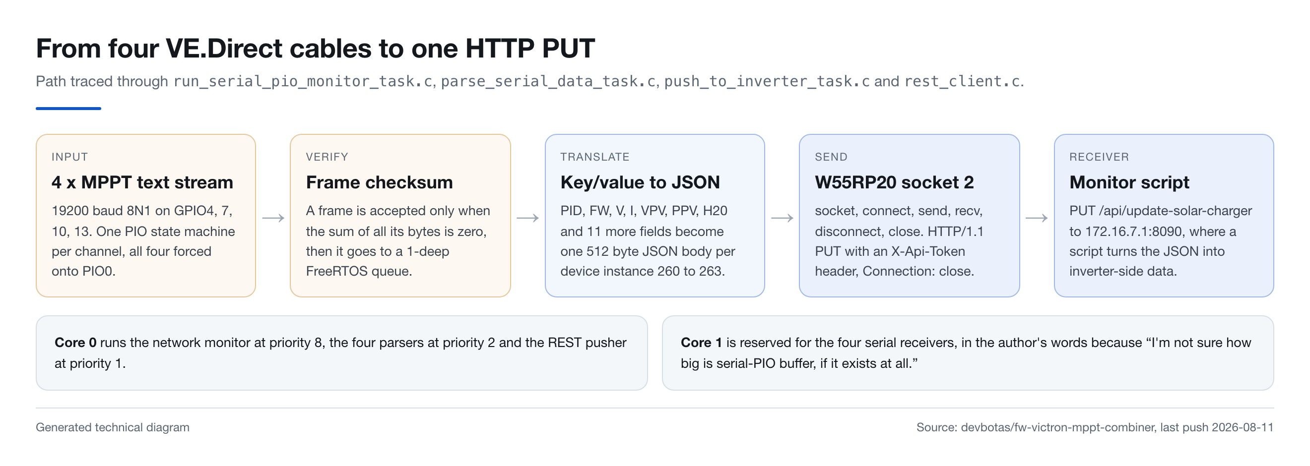
Validation happens before any network work. run_serial_pio_monitor_task.c accepts a frame only when the sum of all its bytes is zero, which is how Victron builds the checksum, and a rejected frame resets both buffers and drops the channel LED. That gate earned its place the hard way, judging by a commit on 2026-08-10: "Fell for the rookie trap. MPPT is sometimes injecting binary data into the stream, which overflew parsing buffers."
The two RP2040 cores are split along the same line. The four serial receivers sit on core 1, with a comment in app/mppt_combiner.c explaining why: "These go to a dedicated Core 1, because I'm not sure how big is serial-PIO buffer, if it exists at all." Core 0 keeps the network monitor at priority 8, the parsers at priority 2 and the REST pusher at priority 1.
The Network Path Runs Straight Into Hardware Sockets
Once a frame is parsed, push_to_inverter_task.c builds a 512 byte JSON body carrying product id, firmware version, serial number, battery voltage and current, panel voltage and power, today's yield, load state and uptime, then hands it to rest_put. From that point app/rest_client/rest_client.c talks to the W55RP20 itself rather than to a stack.
/* app/rest_client/rest_client.c */
int8_t opened_socket_number = socket(socket_number, Sn_MR_TCP, 0, 0);
if (opened_socket_number != socket_number) { response_code = REST_NO_SOCKETS; goto error; }

uint8_t connect_result = connect(socket_number, ip, port);
if (connect_result != SOCK_OK) { response_code = REST_NO_CONNECTION_TO_SERVER; goto error; }

uint8_t send_result = send(socket_number, (uint8_t*)request, strlen(request));
/* ... recv() loop until SOCKERR_SOCKCLOSED ... */

disconnect(socket_number);
close(socket_number);
The socket number is not requested from anywhere. network.h reserves socket 0 for DHCP with #define SOCKET_DHCP 0, rest_get() passes socket 1, and rest_post() and rest_put() both pass socket 2, so three of the eight hardware sockets in the W5500 core are budgeted by hand and the rest stay idle.
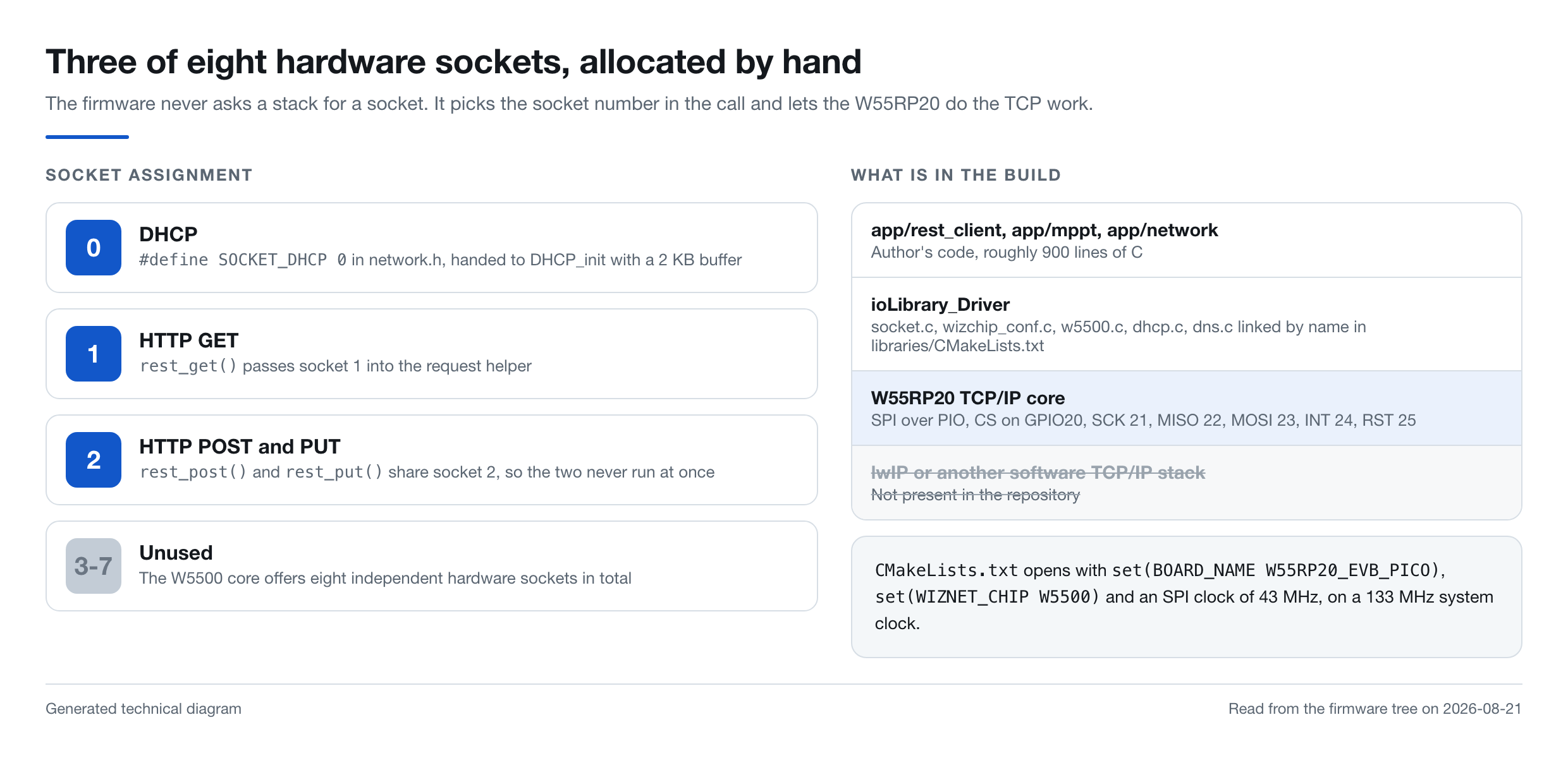
No software TCP/IP stack is present. .gitmodules pulls three submodules, Wiznet/ioLibrary_Driver, raspberrypi/FreeRTOS-Kernel and raspberrypi/pico-sdk, and app/CMakeLists.txt links only ETHERNET_FILES, IOLIBRARY_FILES, DHCP_FILES, DNS_FILES and TIMER_FILES. The single occurrence of the string lwip anywhere in the tree, checked on 2026-08-21, is a leftover comment on line 64 of FreeRTOSConfig.h.
Cable Events, DHCP Restarts and Three Status LEDs
In the combiner firmware, monitor_network_task.c polls wizphy_getphylink() every 100 ms and treats link changes as events. A drop to PHY_LINK_OFF calls DHCP_stop(), clears the address flag and turns off the LED on GPIO2, while a return to PHY_LINK_ON calls initialize_dhcp(), waits a second and resets a retry counter capped at five.
The link transitions are readable on the board itself. The schematic gives D1 the value IP GOOD on GPIO2, D2 the value SERVER GOOD on GPIO3 and D7 the value RUNNING on GPIO28, and the firmware drives exactly those pins from the network task, the REST pusher and a heartbeat blinker, so three LEDs report the lease, the last PUT and the scheduler.
What the W55RP20-EVB-Pico Leaves the Carrier to Use
The root CMakeLists.txt of the combiner firmware names the target board and the chip in its opening statements.
# CMakeLists.txt, top of file, comments and blank lines removed
set(BOARD_NAME W55RP20_EVB_PICO)
set(WIZCHIP_SPI_SCLK_SPEED 43)
add_definitions(-D_WIZCHIP_SPI_SCLK_SPEED=${WIZCHIP_SPI_SCLK_SPEED})
set(WIZNET_CHIP W5500)
add_definitions(-D_WIZCHIP_=W5500)
add_definitions(-DDEVICE_BOARD_NAME=W55RP20_EVB_PICO)
Under that board name, port/ioLibrary_Driver/inc/wizchip_spi.h enables the PIO SPI path and fixes six pins: CS on GPIO20, SCK 21, MISO 22, MOSI 23, INT 24 and RST 25. The system clock is 133 MHz in app/system/system.h, and the 43 MHz SPI request is the number the driver converts into its PIO divider.
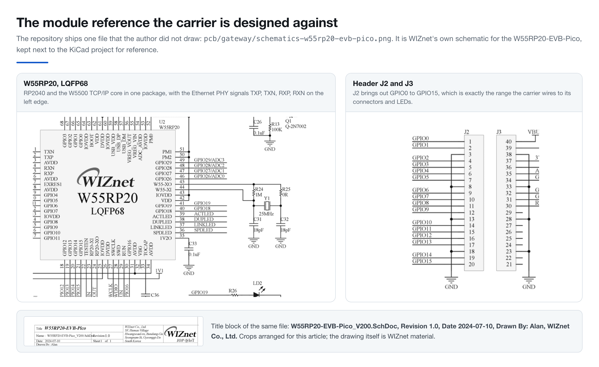
The reserved pin range also shapes the carrier. pcb/gateway/schematics-w55rp20-evb-pico.png is not the author's drawing: its title block reads W55RP20-EVB-Pico_V200.SchDoc, Revision 1.0, Date 2024-07-10, Drawn By: Alan, WIZnet Co., Ltd., and it is the module reference the board is designed against. In the KiCad symbol taken from that reference, the header positions that would be GP16 through GP22 on a Pico strip are marked NC, so the carrier works entirely within GPIO0 to GPIO15 plus GPIO28, and every one of those pins lands on a connector or an LED.
The Rest of the Wires-First Set
The gateway shares its repository with three board types that explain the project name. A voltage converter takes 12 to 24 V and produces the 3.3 V that arrives on pin 4 of the gateway's connectors, and a switcher drives one 12 or 24 V output rated at 4 A around a Renesas SLG47115, wired so that its ON, OFF and TGL lines can go straight to a physical wall switch.
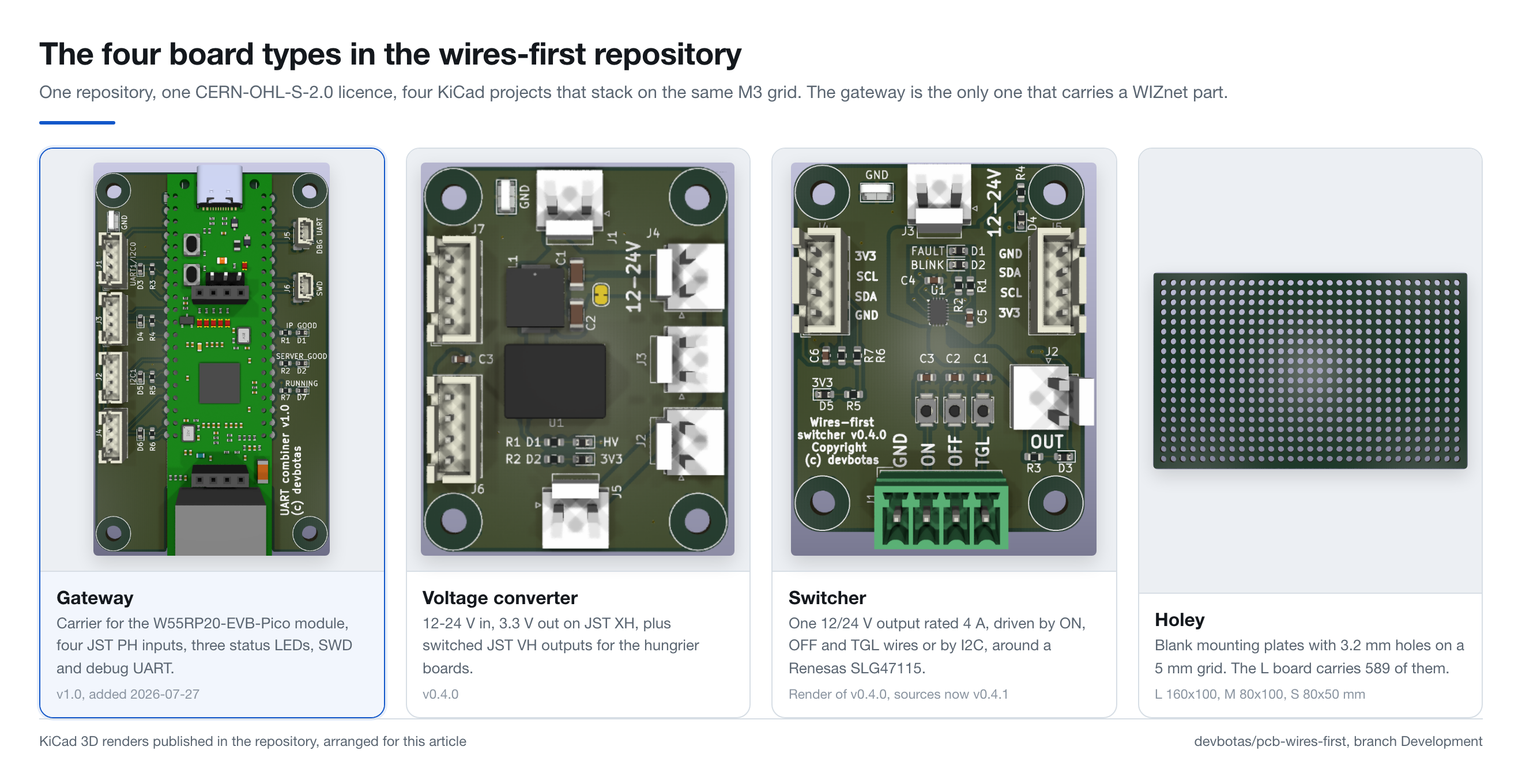
The Holey boards are blank mounting plates with 3.2 mm holes on a 5 mm grid, carrying 135, 285 and 589 holes in the three sizes. The README lists them as 160x100, 100x80 and 80x40 mm, although holey-s.kicad_pcb draws the small plate at 80 by 50 mm with a 15 by 9 grid, which is what makes two of them fit one medium plate exactly as the README describes.
What the Repository Does Not Publish
The pcb-wires-first and fw-victron-mppt-combiner repositories are both recent and small, so it is worth being precise about what a reader can rebuild from them as of 2026-08-21.
- Gerbers exist for the Holey plates only; the gateway ships KiCad sources with no fabrication output and no BOM.
- No photograph of an assembled board appears in either repository. The four board images are KiCad 3D viewer exports that still carry the exporter's
logicalX,logicalYandsubGeometryListchunks, and the fifth image in the tree is WIZnet's module schematic. - Neither repository has a GitHub release, an open issue or a fork, and both sit at zero stars. The hardware repository carries one git tag,
Versions/0.1.0, placed on 2026-05-11 with the message "Doing a draft release." - The server address is compiled in as 172.16.7.1 port 8090, and the API token ships as the literal string
change-me. - The Venus OS monitor script that receives the PUT is described in the README but is not part of either repository.
- Commit messages are the only sign that hardware was built: "Debugging on a real board" on 2026-07-07, which added the switcher's Renesas configuration file, and "Adding issues after live testing and soldering" on 2026-08-20, which touched
pcb/switcheralone. Neither commit touches the gateway.
The licences are unusually clear for a personal project. The hardware repository carries the full CERN Open Hardware Licence Version 2 Strongly Reciprocal text, so derived boards inherit the same terms, while the firmware is Apache-2.0 and credits its origin: "This repo was originally based on WizNET's getting started repo. I removed the examples and replaces with my app."
Related WIZnet Maker Projects
W55RP20 Ethernet Bring-Up for a VSCP NFC Lock starts from the same WIZnet FreeRTOS C example and reaches the point where DHCP and the socket layer come up. That project stops at bring-up before the lock logic exists, while the combiner carries a finished payload and its own PCB, so the pair shows both ends of one starter tree.
WIZnet Success Stories: SNMP-based Environmental Monitoring Converter Using W55RP20 solves the same problem from the product side. FLS ships a converter that speaks SNMP to a monitoring system, while the combiner speaks one hardcoded HTTP PUT to one script, which brackets the same job at the commercial and the one-person ends.
Building a VCP, a virtual serial port, on the W55RP20-EVB-Pico puts a serial line on the network with the same module, written in Japanese. A virtual COM port keeps the byte stream transparent end to end, while the combiner parses VE.Direct frames, verifies the Victron checksum and emits JSON, which is the trade between a generic bridge and a protocol-aware one.
How to Build an Industrial Geiger-Mueller Datalogger with W55RP20-EVB-PICO places the same module at the centre of a fixed wired installation, a radiation monitoring station from Signal Elektronik. One stream instead of four and a vendor instead of an individual, with the same conclusion about where the module fits: unattended equipment that has to keep reporting over a cable.
FAQ
Q. What does this project use the W55RP20 for? The W55RP20 supplies both the RP2040 that runs the firmware and the W5500 TCP/IP core that carries every HTTP request, so one package replaces a separate microcontroller and Ethernet controller on a 47.4 by 77.4 mm board.
Q. Does the firmware use lwIP or any software TCP/IP stack? No. app/CMakeLists.txt links only the ioLibrary Ethernet, DHCP, DNS and timer targets, and rest_client.c calls socket(), connect(), send(), recv() and close() on hardware sockets 1 and 2, with DHCP on socket 0.
Q. Can the gateway board be built from what is published? The KiCad schematic and board files are published under CERN-OHL-S-2.0, so the design can be reproduced, but no gerbers, BOM or assembly photographs are included for the gateway, unlike the Holey mounting plates which do ship gerber archives.
Q. Why are the serial inputs handled by PIO instead of the RP2040 hardware UARTs? Four simultaneous receivers exceed the two hardware UARTs an RP2040 provides, so each channel runs a PIO soft UART at 19200 baud, and the author's commit message states that all four are forced onto PIO0 because the WIZnet SPI driver occupies PIO1.
Q. Can this be reused for something other than solar chargers? The board is protocol-agnostic: four JST PH connectors carrying ground, two GPIOs and 3.3 V each, plus SWD and a debug UART. Replacing the parser and the JSON body leaves the PIO receivers, the checksum gate and the socket code intact.
-
pcb-wires-first repository
The hardware project. Four KiCad board types under CERN-OHL-S-2.0, default branch Development, last push 2026-08-20.

-
Gateway KiCad project
Schematic, board and project files for the W55RP20-EVB-Pico carrier, plus WIZnet's own module reference schematic. Added 2026-07-27.
-
fw-victron-mppt-combiner firmware
Apache-2.0 firmware that reads four VE.Direct serial streams at 19200 baud and pushes JSON over Ethernet. Created 2026-08-05, last push 2026-08-11.
-
rest_client.c, the hardware socket path
socket(Sn_MR_TCP), connect, send, recv, disconnect, close on manually assigned socket numbers, with no software TCP/IP stack in the build.
-
WIZnet-PICO-FREERTOS-C (upstream project)
The WIZnet FreeRTOS example this firmware started from. The author keeps a fork of it at devbotas/WIZnet-PICO-FREERTOS-C, and the firmware README credits the example directly.
-
WIZnet ioLibrary_Driver
Submodule providing socket.c, wizchip_conf.c, w5500.c, dhcp.c and dns.c, the only network code linked into the build.
-
WIZnet W55RP20 product documentation
Official page for the RP2040 plus W5500 package used here, including the eight hardware sockets the firmware allocates by hand.
-
WIZnet W55RP20-EVB-Pico
The development module the carrier board is built around, and the source of the reference schematic kept in pcb/gateway.


