


How Does a 10BASE-T1L Field Port Reach Standard Ethernet Through a W5500?
In this open KiCad gateway an ADIN1110 holds the 10BASE-T1L pair and a W5500 carries it onto standard Ethernet, both on one ESP32-S3 over separate SPI buses.

WIZnet - W5500
x 1

U502 on the dedicated Wiznet-W5500 schematic sheet, the standard Ethernet controller on the uplink side. Connected to the ESP32-S3-MINI-1 over a dedicated SPI bus (ETH-SCK, ETH-MOSI, ETH-MISO, ETH-nCS
Two Ethernet Types on One 100 x 54 mm Board
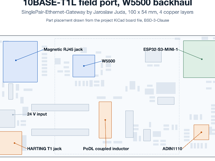
Jaroslaw Juda gives Torun, Poland as his location on a GitHub account holding six public repositories, among them the Analog Devices ADIN1100 non-OS driver, a fork of the PcapPlusPlus packet library, and his own KiCad hardware. SinglePair-Ethernet-Gateway is one of those designs, published under BSD-3-Clause with the notice "Copyright (c) 2024, Jaroslaw Juda". A 10BASE-T1L instrument speaks Ethernet over one twisted pair, the network it must join speaks Ethernet over an RJ45, and this board is the piece between them. A WIZnet W5500 is its RJ45 half.
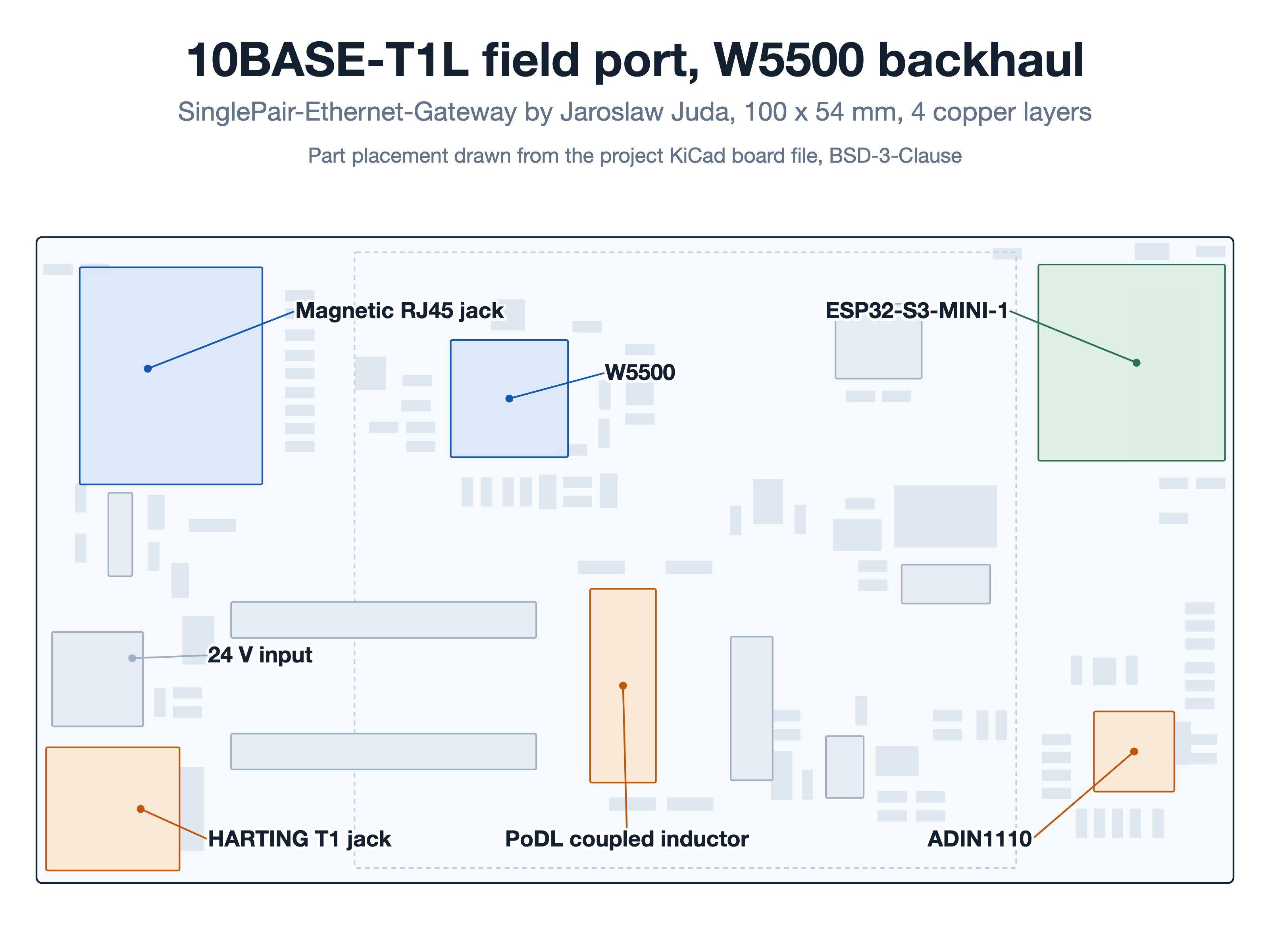
The design is hardware only. The repository holds a complete KiCad 9 project, 119 components across five schematic sheets, a four-layer PCB of exactly 100.00 by 54.00 mm carrying 176 nets, but no firmware. Every fact here comes from the schematics, the board file, the netlist and the bill of materials.
What 10BASE-T1L Changes About a Field Cable
10BASE-T1L is the IEEE 802.3cg variant of Ethernet that runs 10 Mbit/s, full duplex, over a single twisted pair and reaches up to 1,000 m. Process instruments have used two-wire loops for decades, so the appeal is direct: the pair that already runs to a sensor can carry IP, and Power over Data Line pushes DC down it. The missing piece is what turns that pair into something an ordinary microcontroller can address.
The Analog Devices ADIN1110 is that piece. It is a MAC-PHY, carrying the Ethernet media access controller and the 10BASE-T1L physical layer in one part, and it presents an SPI port to the host instead of the MII bus a bare PHY needs. Here the ADIN1110BCPZ is U302, with 41 pads on nets in the published PCB.
One ESP32-S3, Two Independent SPI Links
The host is MOD201, an ESP32-S3-MINI-1-N8, and the two Ethernet controllers do not share a bus. The netlist gives each one its own six nets, named with an ETH- prefix for the W5500 and an SPE- prefix for the ADIN1110, and each set lands on a different group of ESP32-S3 pins.
| Net | ESP32-S3 pin | Destination | Pin function |
|---|---|---|---|
| ETH-SCK | IO48 | W5500 pin 33 | SCLK |
| ETH-MOSI | IO33 | W5500 pin 35 | MOSI |
| ETH-MISO | IO34 | W5500 pin 34 | MISO |
| ETH-nCS | IO35 | W5500 pin 32 | SCS |
| ETH-nINT | IO26 | W5500 pin 36 | INT |
| ETH-nRST | IO21 | W5500 pin 37 | RST |
| SPE-SCK | IO39 | ADIN1110 pin 38 | SCLK |
| SPE-SDI | IO38 | ADIN1110 pin 1 | SDI |
| SPE-SDO | IO37 | ADIN1110 pin 2 | SDO |
| SPE-nCS | IO40 | ADIN1110 pin 29 | CS_N |
| SPE-nINT | IO41 | ADIN1110 pin 25 | INT_N |
| SPE-nRST | IO36 | ADIN1110 pin 5 | RESET_N |
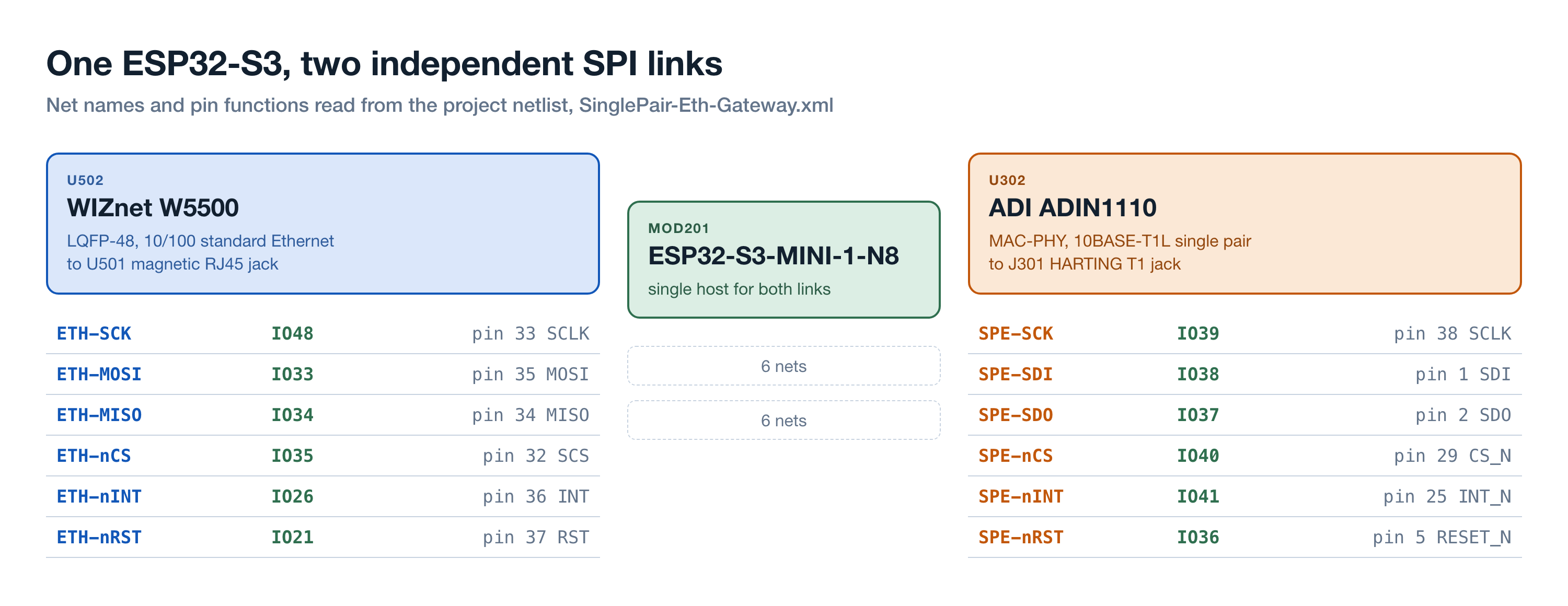
Separate chip selects, interrupt lines and reset lines mean firmware can bring either side up, hold the other in reset, and service each interrupt without arbitration. A solder jumper, JP301, sits on the ADIN1110 SPI_CFG1 pin and can tie it to ground or to 3.3 V, which is where the choice of SPI protocol mode is made on that part.
Where the W5500 Sits in the Chain
The W5500 is U502 on a dedicated schematic sheet the project names Wiznet-W5500. Its netlist entry describes it as a "10/100Mb SPI Ethernet controller with TCP/IP stack, LQFP-48", carries the keyword "WIZnet Ethernet controller", and links the W5500 datasheet revision 1.0.9e. The current schematic sheet marks U502 (dnp no) and (in_bom yes), and in the board file all 48 pads sit on nets.
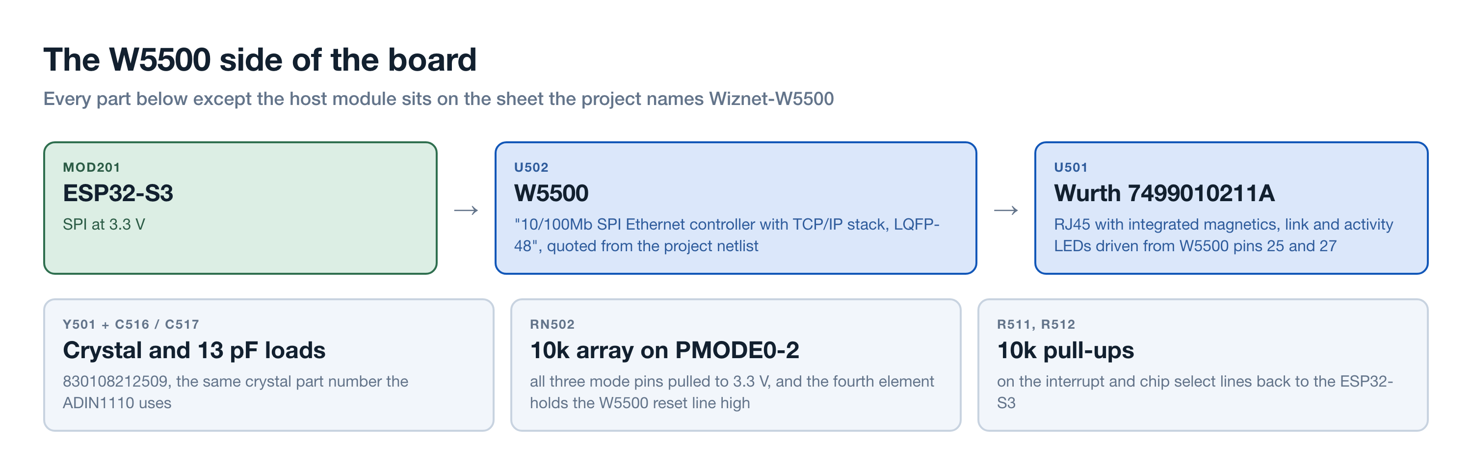
The rest of that sheet makes the backhaul a real port. U501 is a Wurth 7499010211A, an RJ45 jack with magnetics built in, and the W5500 LINKLED and ACTLED outputs on pins 25 and 27 drive its indicator LEDs. Y501 is a crystal, part 830108212509, the same part the ADIN1110 uses, with 13 pF load capacitors, and RN502 is a 10k array that pulls PMODE0, PMODE1 and PMODE2 to 3.3 V and holds the reset line high on its fourth element. R511 and R512 add 10k pull-ups on the interrupt and chip select lines.
The W5500 carries its TCP/IP stack in hardware rather than in host software. What this design's firmware would do with that is not published.
What the Single Pair Carries, and What Guards It
The field side is more heavily protected than the backhaul, which fits where that cable goes. The pair lands on J301, a HARTING 09452812800 the netlist describes as a "T1 Industrial angle jack AH IP20", and on J302, a two-pole screw terminal on the same nets, so an installer can use the industrial connector or bare wire.
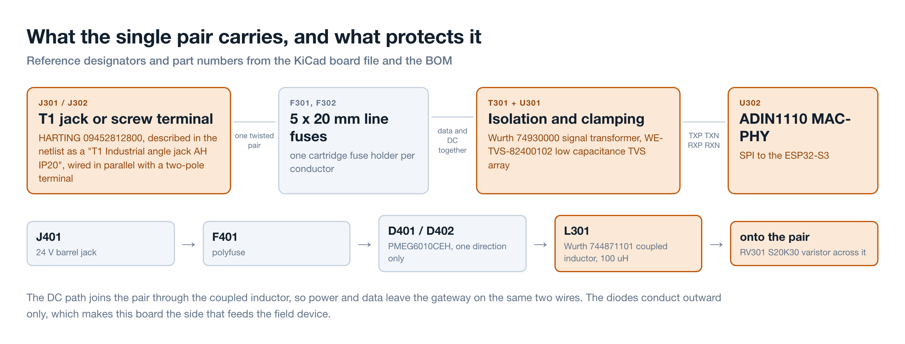
Each conductor then passes through its own 5 by 20 mm cartridge fuse holder, F301 and F302, then blocking capacitors into T301, a Wurth 74930000 the netlist calls a "WE-STST Super Tiny Signal Transformer 10/100/1000 Base-T". A WE-TVS-82400102 low capacitance TVS array clamps the line ahead of the ADIN1110 TXP, TXN, RXP and RXN pins.
Power joins the same pair through L301, a Wurth 744871101 coupled inductor of 100 uH, with an S20K30 varistor across the conductors. Two PMEG6010CEH Schottky diodes set the direction: D401 conducts from the 24 V rail onto the pair and D402 completes the return, neither the other way. This gateway feeds the field device rather than drawing power from the cable.
Two Ways to Power It, and One Rail
The board takes 24 V on J401, a Wurth 694108301002 barrel jack, behind polyfuse F401. That rail both sources the Power over Data Line injection onto the single pair and feeds U401, a VXO7803-1000 module in a TO-220 outline, whose output reaches the 3.3 V rail through D403. A micro-B USB connector, J203, is the second path, through polyfuse F201 into IC401, an STMicroelectronics LDL112PV33R the netlist calls a "1.2 A low quiescent current LDO with reverse current protection". Both reach the same 3.3 V rail, so the board can come up on a bench over USB and still feed a field device once 24 V arrives.
The Arduino Header Is an Expansion Port, Not an UNO Clone
U602 is drawn with a symbol named Arduino_UNO_4, and its pin names confirm it: BOOT, VRTC, OFF, D10/CS/CANTX0 and D13/SCK/CANRX0 are UNO R4 names, not UNO R3. Only seven signals are routed through it: D13/SCK, D12/CIPO, D11/COPI, D10/CS, D9 as an interrupt, D1/TX0 and D0/RX0. Twenty-two header pins, including A0 to A5, SDA, SCL and D2 to D8, are left unconnected.
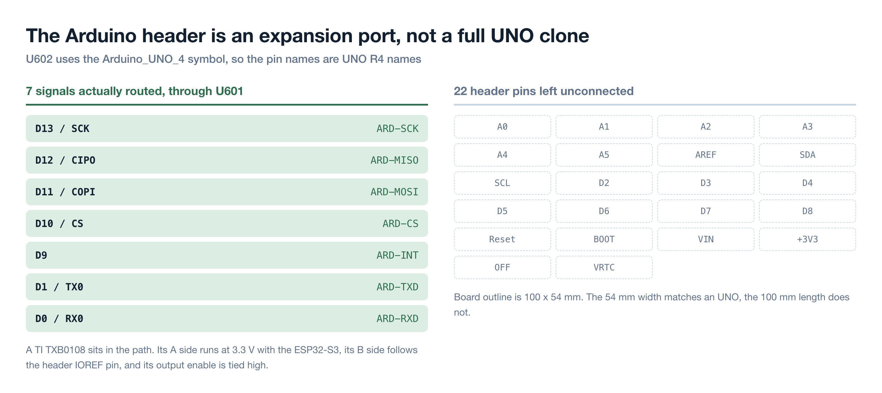
Every routed signal passes through U601, whose BOM value is TXB0108PWR with a datasheet link to the TI TXB0108. Its A side runs at 3.3 V with the ESP32-S3, its output enable is tied high, and its B side takes the header IOREF pin, so a shield sets the voltage on its own side. The header is a shield-shaped expansion port for SPI and a serial line rather than an attempt at UNO compatibility, and the outline agrees: 54 mm wide, within a millimetre of an UNO, but 100 mm long against its 68.6 mm.
What the Design Files Say About the Rest of the Bench
One detail lives only inside the schematic files. KiCad records a symbol instance path for every project a sheet belongs to, and these sheets carry four names. The W5500 sheet holds 82 instances for SinglePair-Eth-Gateway, 78 for a project called Hemispherical-3D-Camera, 14 for gateway-LoRa-T1L and 12 for one named simply Ethernet; the ADIN1110 sheet carries 67 for gateway-LoRa-T1L. These sheets are reusable blocks the designer drops into several boards, a W5500 sheet among them.
Juda's own Hackaday.io page fits that pattern. He documents a 3D IP camera over single pair Ethernet there, created 13 August 2023 and showing 443 views when checked on 27 August 2026, where he writes that "the W5300 chip provides both PHY and MAC interface. Direct PHY for UTP cable, and via MII and the ADIN1100 chip PHY interface for Single Pair Ethernet". The gateway inverts that, giving the W5500 and the ADIN1110 one SPI port each instead of hanging a single-pair PHY off a WIZnet MII bus.
What Is Published and What Is Not
The repository is a hardware release, and the gaps are worth naming plainly.
| Item | What the repository holds | Last commit |
|---|---|---|
| Schematics, five sheets | Complete KiCad 9 project, version 20250114 | 6 August 2025 |
| PCB | Four layers, 119 footprints, 176 nets | 6 August 2025 |
| Netlist and BOM | Generated by Eeschema 7.0.10 | 26 January 2024 |
| README | 29 bytes, the project name only | 1 January 2024 |
| software/ | An empty .gitkeep file | 1 January 2024 |
The repository was created on 1 January 2024 and has four commits. The last, on 6 August 2025, is titled "Zmiany schematu po montażu", Polish for schematic changes after assembly, suggesting a board was built and the drawings corrected against it. The netlist and BOM predate that revision by more than eighteen months, so the current schematic and board files are the reliable source. On 27 August 2026 the repository showed 0 stars and 0 forks.
There is no firmware, no photograph and no assembly documentation, so nothing says how the two interfaces are bridged, or whether frames are forwarded at layer 2 or terminated and re-sent. What the design does give is a buildable reference for a 10BASE-T1L port and a standard Ethernet port on one board, with protection, isolation and power injection parts already chosen.
Related WIZnet Maker Projects
W5300 IP 3D Camera over Single Pair Ethernet is the same maker's earlier post on this site. Both put WIZnet silicon on a single-pair link, but the camera is an endpoint pairing a W5300 with an ADIN1100 PHY over MII, while the gateway is infrastructure pairing a W5500 with an ADIN1110 MAC-PHY over two SPI ports. Read together they show one designer moving from an MII-attached PHY to an SPI MAC-PHY.
I built an Arduino shield with WIZnet + ADI ADIN1101 approaches the same problem from the other side. That project is a shield that adds single-pair Ethernet to an existing Arduino, whereas this board is a standalone gateway that only exposes an Arduino-shaped header. The shield asks what a host board gains, the gateway what a field cable needs.
W5500 Ethernet Controller Schematic For KiCad is useful for reusing the backhaul half: it covers a reference W5500 sheet on its own, while this project shows the same block beside a second Ethernet controller, a level translator and a Power over Data Line branch.
FAQ
Q. What does the W5500 do in this gateway? The W5500 is the standard Ethernet controller on the uplink, connected to the ESP32-S3 over a dedicated SPI bus and to a Wurth 7499010211A magnetic RJ45 jack. Its hardwired TCP/IP stack means the host needs no software stack for that port.
Q. Why an ADIN1110 rather than an ADIN1100? The ADIN1110 is a MAC-PHY: it includes the Ethernet MAC and connects over SPI, while the ADIN1100 is a PHY needing a MAC and an MII bus. The ADIN1110 lets one ESP32-S3 drive both Ethernet ports over SPI.
Q. Is firmware included? No. The software folder holds only an empty .gitkeep file, so the repository is a hardware design and the bridging behaviour is left to whoever builds it.
Q. Can this board power a 10BASE-T1L device over the same pair? The design injects the 24 V input onto the pair through a Wurth 744871101 coupled inductor, with diodes that conduct outward only, so it feeds a field device rather than drawing power from the cable.
Q. Will an Arduino shield work on the header? Only partly. Seven signals are routed, covering SPI, an interrupt on D9 and the D0 and D1 serial pins, while 22 header pins including all analog inputs and the I2C pins are unconnected.
-
SinglePair-Ethernet-Gateway repository
The full KiCad project under BSD-3-Clause. Hardware only; the software folder holds an empty .gitkeep.

-
W5500 schematic sheet (W5500.kicad_sch)
U502 with its crystal, PMODE pull-up array, pull-ups and the Wurth 7499010211A magnetic RJ45 jack. Last updated 6 August 2025 with KiCad 9.
-
ADIN1110 schematic sheet (ADIN1110.kicad_sch)
The 10BASE-T1L front end: HARTING T1 jack, line fuses, Wurth 74930000 transformer, TVS array and the PoDL coupled inductor.
-
Board file (SinglePair-Eth-Gateway.kicad_pcb)
Four copper layers, 119 footprints, 176 nets, board outline 100.00 x 54.00 mm.
-
Bill of materials (SinglePair-Eth-Gateway.csv)
Generated by Eeschema 7.0.10 on 26 January 2024. Lists U502 W5500 in LQFP-48 with no DNP marking.
-
Netlist (SinglePair-Eth-Gateway.xml)
Source of the ETH- and SPE- net names, the W5500 libsource description and the HARTING and Wurth part descriptions quoted in the article.
-
WIZnet W5500 documentation
Hardwired TCP/IP Ethernet controller with SPI host interface, the part used as U502.
-
3D IP Camera over Single Pair Ethernet (Hackaday.io)
The same maker's earlier single-pair project, where a W5300 provides MAC and PHY and an ADIN1100 attaches over MII.
-
IEEE 802.3cg task force (10BASE-T1L and 10BASE-T1S)
The standards work behind 10 Mbit/s single-pair Ethernet, the link type this gateway terminates.


