
GPS-Disciplined Stratum-1 NTP Server with W5500 Hardware Timestamping
High-precision NTP server on ESP32 + W5500 using GPS PPS discipline, MCPWM hardware capture, and ARP-aware transmit timing
Espressif - ESP32
x 1

WIZnet - W5500
x 1
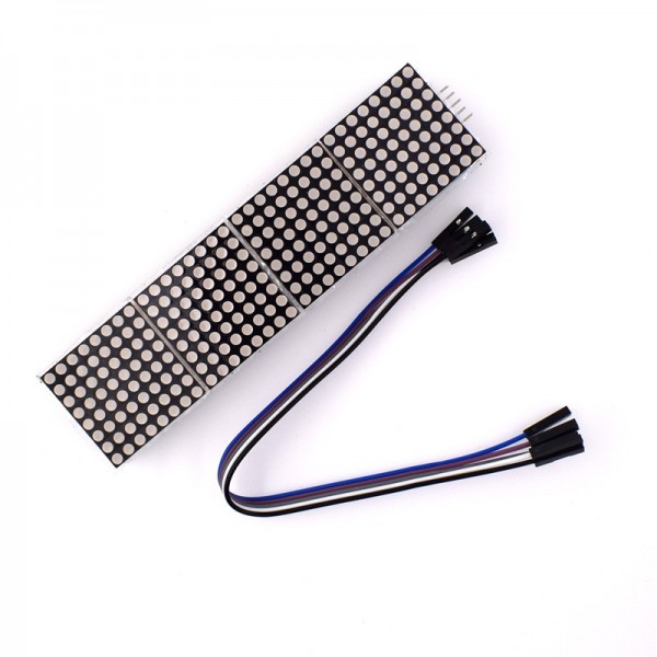
Generic - LED Matrix 32x8 MAX7219
x 1
A Stratum-1 Time Server on Your Desk
Most ESP32-based NTP projects are NTP clients — they pull time from the internet. This project flips that: it turns an ESP32 into an NTP server, providing Stratum-1 time to every device on the local network. The time source is a GPS receiver with PPS (Pulse Per Second) output, disciplined through a sophisticated PI servo loop with hardware-assisted timestamping.
What sets this project apart from typical GPS-NTP implementations is the depth of its timing pipeline. On the W5500 Ethernet path, the firmware primes the ARP cache before stamping the transmit timestamp, eliminating millisecond-scale delays that would otherwise corrupt NTP accuracy. The PPS edge itself is captured via the ESP32's MCPWM (Motor Control PWM) hardware peripheral rather than a software ISR, avoiding interrupt latency jitter entirely.
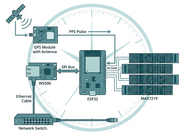
System Architecture
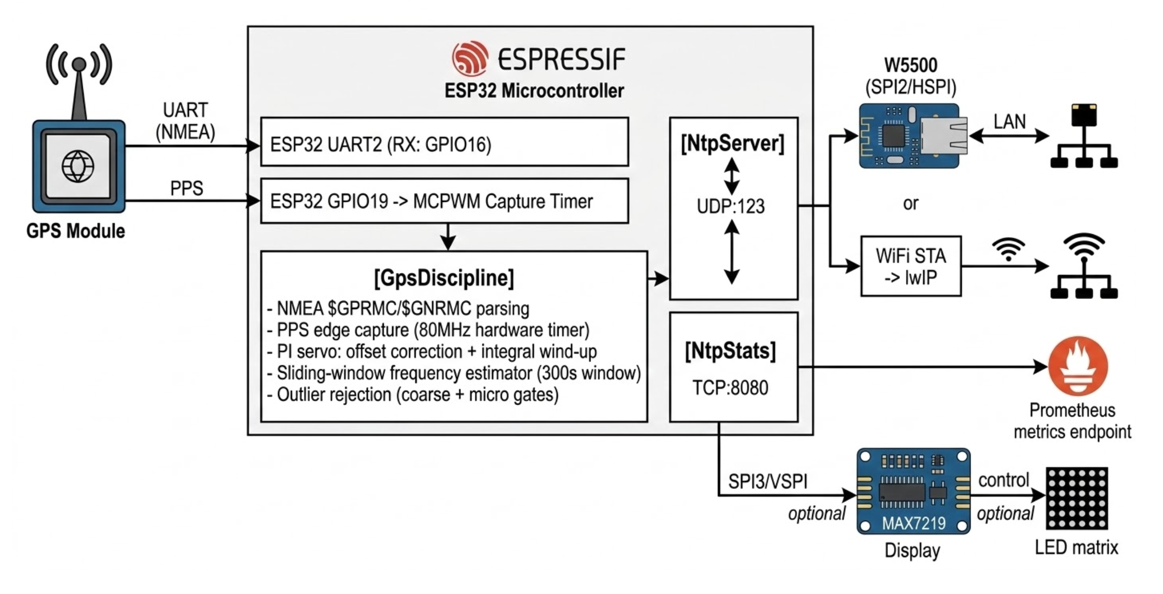
The W5500 and the MAX7219 display run on separate SPI buses (HSPI and VSPI respectively), avoiding bus contention. The W5500 communicates through WIZnet's ioLibrary_Driver at the register level — this project does not use ESP-IDF's built-in Ethernet stack, giving the firmware direct control over socket operations and timing.
PPS Discipline: Where the Precision Comes From
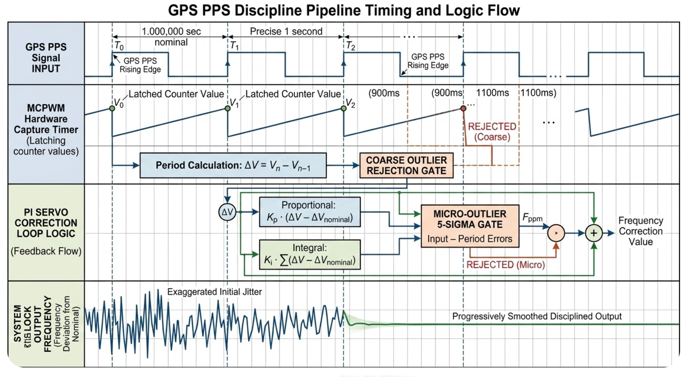
The heart of this project is GpsDiscipline (components/gps/gps.cpp). Rather than using a GPIO interrupt (which introduces variable ISR latency), the PPS signal is captured by the ESP32's MCPWM hardware capture timer, which latches a counter value at the exact GPIO edge:
// components/gps/gps.cpp:L52-L71
// PPS capture via MCPWM hardware — latches timer at exact GPIO edge
mcpwm_capture_timer_config_t cap_timer_cfg = {};
cap_timer_cfg.group_id = 0;
cap_timer_cfg.clk_src = MCPWM_CAPTURE_CLK_SRC_DEFAULT;
ESP_ERROR_CHECK(mcpwm_new_capture_timer(&cap_timer_cfg, &capTimer));

mcpwm_capture_channel_config_t cap_ch_cfg = {};
cap_ch_cfg.gpio_num = ppsGpio;
cap_ch_cfg.prescale = 1;
cap_ch_cfg.flags.pos_edge = 1;
cap_ch_cfg.flags.neg_edge = 0;
ESP_ERROR_CHECK(mcpwm_new_capture_channel(capTimer, &cap_ch_cfg, &capChannel));
This gives a resolution determined by the MCPWM clock (80 MHz on ESP32), meaning the PPS edge timestamp has ~12.5ns granularity. The ISR callback is minimal — it stores the capture value and sets a flag, with all heavy processing deferred to the main loop.
The clock discipline uses a PI (Proportional-Integral) servo with an analytical offset model. On each clean PPS pulse, the controller computes a correction:
// components/gps/gps.cpp:L230-L237
// PI servo: only update on clean (non-outlier) pulses
if (!outlier && statPpsCount >= 20 && prevPpsEdgeForOffset != 0) {
    statLastOffsetSec = offset;
    double offsetUs = offset * 1e6;
    proportionalUs = -0.5 * offsetUs;
    clockCorrectionUs -= 0.05 * offsetUs;
    if (clockCorrectionUs > 50)  clockCorrectionUs = 50;
    if (clockCorrectionUs < -50) clockCorrectionUs = -50;
}
The proportional gain (0.5) provides fast tracking, while the integral term (0.05 per step, clamped to ±50µs) compensates for systematic offset. A sliding-window frequency estimator resets every ~300 seconds to avoid stale boot data dominating the correction.
PPS outlier rejection operates in two stages. A coarse gate rejects intervals outside 900ms–1100ms (catching missed or spurious pulses). A secondary micro-outlier gate uses an adaptive threshold of max(10µs, 5σ) on the EWMA jitter estimate, catching ISR latency spikes that pass the coarse gate:
// components/gps/gps.cpp:L292-L299
double threshold = (sigma > 2.0) ? 5.0 * sigma : 10.0;  // max(10µs, 5σ)
if (absDiff < threshold) {
    const double alphaJ = 0.05;
    ppsIntervalMeanUs += alphaJ * diff;
    ppsJitterVarUs2 = (1.0 - alphaJ) * (ppsJitterVarUs2 + alphaJ * diff * diff);
    statPpsJitterSec = sqrt(ppsJitterVarUs2) / 1e6;
}
W5500 NTP Path: ARP Priming for Transmit Accuracy
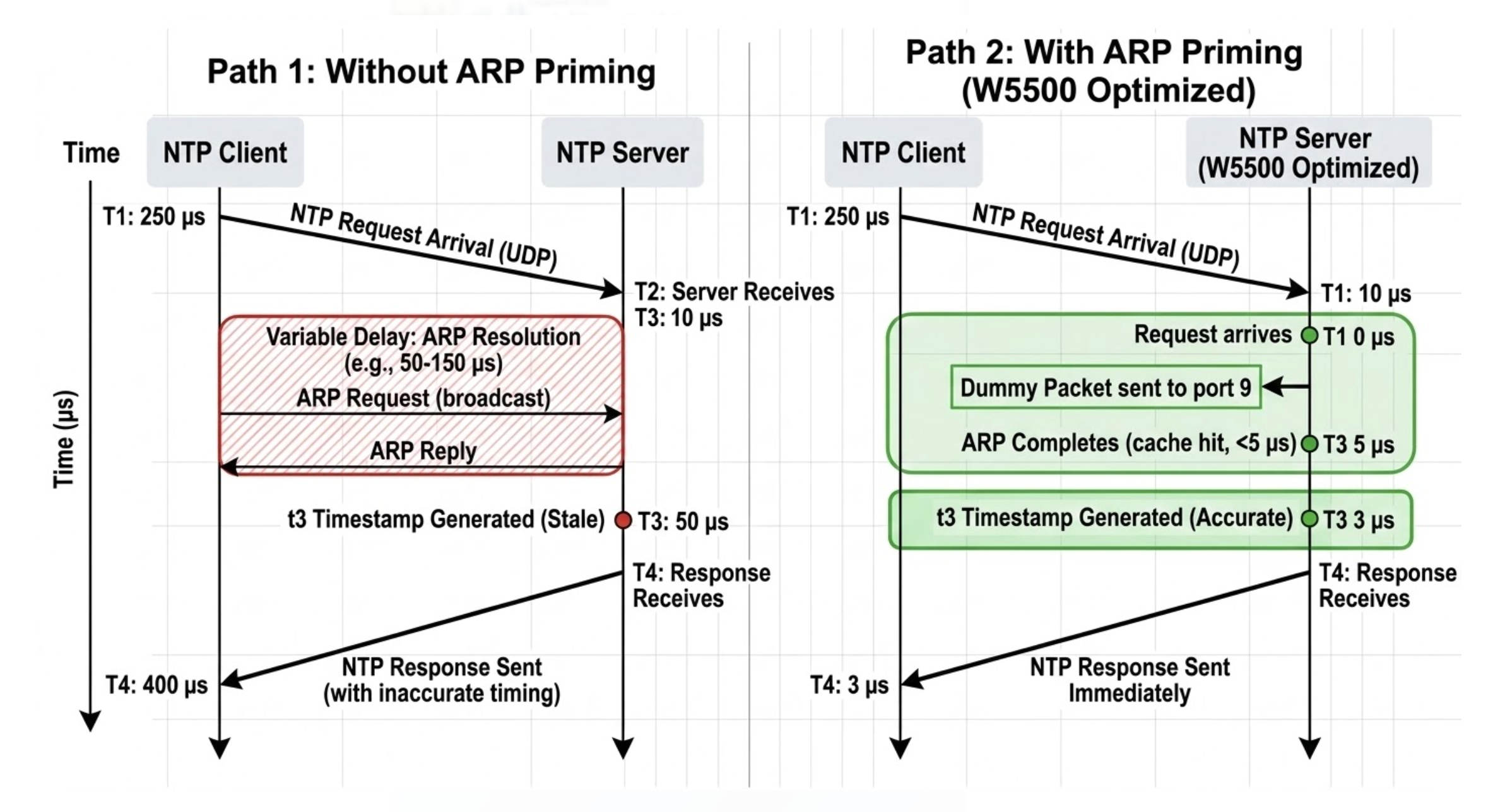
In NTP, the transmit timestamp (t3) is critical — it tells the client exactly when the server sent the response. A stale t3 caused by ARP resolution delay can introduce milliseconds of error.
The W5500 code path in NtpServer::loop() addresses this with a deliberate ARP priming step before stamping t3:
// components/ntp_server/ntp_server.cpp:L192-L199
// W5500: prime ARP cache first so t3 isn't stale due to ARP latency
w5k_arp_prime((uint8_t)sock, from_ip);

// NOW stamp t3 — ARP is resolved, sendto will depart immediately
uint32_t t3_sec, t3_frac;
computeNtpTimestamp(esp_timer_get_time(), locked, t3_sec, t3_frac);
wr_ntp_ts(rsp, 40, t3_sec, t3_frac);
The w5k_arp_prime() function sends a 1-byte dummy packet to port 9 (RFC 863 discard) and blocks until the W5500 signals SENDOK, ensuring the ARP cache is warm. Only then does the firmware stamp t3 and send the real NTP response. This technique leverages the W5500's hardware TCP/IP stack — the chip handles ARP resolution internally, so the firmware just needs to trigger it proactively.
On the WiFi path, the same NTP logic applies but without ARP priming — lwIP handles ARP transparently, and the transmit path is less deterministic regardless.
NTP Timestamp Synthesis
The NTP timestamps are synthesized by interpolating from the last PPS edge using the ESP32's monotonic timer, with frequency correction applied:
// components/ntp_server/ntp_server.cpp:L71-L88
void NtpServer::computeNtpTimestamp(uint64_t monoUs, bool locked, uint32_t& sec1900, uint32_t& frac) {
    if (locked && gps) {
        uint64_t lastPpsUs = gps->getLastPpsMonotonicUs();
        uint32_t ppsSec1900, ppsFrac;
        if (gps->getLastPps(ppsSec1900, ppsFrac)) {
            uint64_t rawDelta = monoUs - lastPpsUs;
            int64_t freqCorr = (int64_t)(-gps->getFrequencyPpm() * 1e-6 * (double)rawDelta);
            uint64_t correctedDelta = rawDelta + freqCorr;
            sec1900 = ppsSec1900 + (uint32_t)(correctedDelta / 1000000ULL);
            frac = (uint32_t)(((correctedDelta % 1000000ULL) << 32) / 1000000ULL);
            return;
        }
    }
    // Fallback: use system time without GPS discipline
    struct timeval tv;
    gettimeofday(&tv, nullptr);
    sec1900 = (uint32_t)((uint64_t)tv.tv_sec + 2208988800ULL);
    frac = 0;
}
The delta since the last PPS edge is corrected by the measured local oscillator frequency error (ppm), converting the monotonic timer's tick count into a GPS-disciplined NTP timestamp with sub-millisecond accuracy.
Prometheus Metrics for Monitoring
The stats HTTP server (components/ntp_stats/ntp_stats.cpp) exposes a /metrics endpoint on TCP port 8080, formatted as Prometheus text exposition. Key metrics include clock offset, RMS offset, frequency error (ppm), PPS jitter, root dispersion, GPS lock status, stratum, uptime, total NTP requests served, PPS count, and PPS rejects. This makes integration with Grafana or any Prometheus-compatible monitoring stack straightforward.
The implementation works over either W5500 (using the w5k TCP wrapper) or WiFi (using lwIP sockets), depending on the selected network interface.
Configurable via menuconfig
All hardware pins, network interface selection, IP configuration (DHCP or static), timezone, and display settings are exposed through ESP-IDF's Kconfig system (main/Kconfig.projbuild). The default configuration selects W5500 Ethernet, but switching to WiFi STA requires only changing one menuconfig option and providing SSID/password.
The W5500 uses dedicated SPI pins on HSPI: MOSI (GPIO33), MISO (GPIO35), SCLK (GPIO32), CS (GPIO25), INT (GPIO34), RST (GPIO26). GPIO35 and GPIO34 are input-only pins on ESP32, matched to their roles as MISO and INT respectively — a careful pin assignment choice.
What Could Be Improved
The project is functional and well-structured, but a few areas could benefit from additional work. There is no NTP client mode — the device only serves time, so it cannot cross-validate against upstream NTP servers. The W5500 driver uses 2KB socket buffers for all 8 sockets (16KB total), which is conservative; since only 2–3 sockets are in use, reallocating more buffer to the NTP socket could reduce packet processing latency. The WiFi path lacks the ARP priming optimization, so transmit timestamps may be slightly less accurate compared to the W5500 path. Finally, there is no watchdog or automatic recovery if GPS lock is permanently lost — the server continues operating with stratum 16 (unsynchronized) but does not attempt reconnection strategies.
FAQ
Q1: What precision can I expect from this NTP server? The GPS PPS signal provides ~100ns accuracy at the source. The MCPWM capture adds ~12.5ns resolution. After the PI servo converges (about 20 PPS pulses), the clock offset typically settles to single-digit microseconds. The ARP priming on the W5500 path eliminates the largest source of network-side jitter. Real-world accuracy depends on the GPS module quality and PPS signal integrity.
Q2: Why does this use WIZnet's ioLibrary directly instead of ESP-IDF's Ethernet driver? ESP-IDF's W5500 Ethernet driver runs through the lwIP stack, which adds processing overhead and non-deterministic timing. By using ioLibrary's socket API directly, the firmware has precise control over when packets are sent and can implement techniques like ARP priming at the W5500 register level. This is essential for an NTP server where transmit timestamp accuracy matters.
Q3: Can I use both Ethernet and WiFi simultaneously? No. The firmware selects one network interface via menuconfig (APP_NETWORK_WIZNET or APP_NETWORK_WIFI). The NTP server and stats endpoint bind to whichever interface is active. The code architecture would support dual-interface operation, but it is not currently implemented.
Q4: What GPS modules are compatible? Any GPS module with UART NMEA output ($GPRMC or $GNRMC sentences) and a PPS output pin. The default baud rate is 9600. Common choices include u-blox NEO-6M, NEO-7M, and NEO-M8T. The "T" (timing) variants of u-blox modules provide higher PPS accuracy in fixed-location mode.
Q5: What does the LED display show? When GPS is locked, the 4× MAX7219 8×8 matrix display shows the current time (HH:MM:SS) with a top-row centisecond indicator that scrolls as an uptime heartbeat. Before GPS lock, a pre-sync glyph animation is shown. The display is entirely optional and can be disabled in menuconfig.
Q6: How does the outlier rejection work? Two stages. First, a coarse gate checks whether the inter-PPS interval falls within 900ms–1100ms — anything outside is clearly a missed or doubled pulse. Second, a micro-outlier gate uses an adaptive threshold of max(10µs, 5σ) based on EWMA jitter statistics, catching ISR scheduling spikes that would contaminate the jitter estimate but pass the coarse gate. Both intervals are measured from MCPWM hardware capture ticks (80MHz), not from esp_timer_get_time(), so ISR dispatch latency does not affect measurement accuracy.
Q7: How do I monitor the server health? Point a browser or Prometheus scraper at http://<device-ip>:8080/metrics. The response includes real-time metrics in Prometheus text exposition format. Key health indicators are ntp_gps_lock (1 = locked), ntp_rms_offset_seconds (lower is better, typically <10µs when stable), and ntp_pps_jitter_seconds (GPS signal quality indicator).