ESP32 GPS Test with W5500
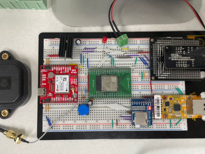
A project testing GPS data using the ESP32 chipset and testing Ethernet communication with the W5500 chip.

Software Apps and online services
Espressif - Espressif ESP-IDF
x 1
Overview
The above project focuses on obtaining and processing location information using the ESP32 development board and a GPS module, with the addition of Wiznet's W5500 to implement ioT over an Ethernet connection.
W5500 in code
#if CONFIG_USER_ETH_W5500_ENABLE == 0
// ethernet init &connection
ESP_LOGI(TAG, "CONFIG_USER_ETH_W5500_ENABLE: %d", CONFIG_USER_ETH_W5500_ENABLE);
spi_eth_module_config_t ethcfg = {
.spi_cs_gpio = USER_ETH_SPI_CS_GPIO,
.int_gpio = USER_ETH_SPI_INT_GPIO,
.phy_reset_gpio = USER_ETH_SPI_PHY_RST_GPIO,
.phy_addr = USER_ETH_SPI_PHY_ADDR_GPIO,
};
ethernet_init(ðcfg);
network_ret = ethernet_connection_check();
if (network_ret == 0)
blink(USER_BLINK_GPIO, 100, 10);
else
blink(USER_BLINK_GPIO, 1000, 2);
#endif
The part you are referring to involves initializing the W5500 Ethernet module and checking the connection status. If the connection is successful, it flashes 10 times quickly, and if the connection fails, it flashes 2 times slowly. From then on, when communicating with the server, it uses TCP communication to transfer data.
Other important codes
Include header files (lines 1-12): Include the necessary header files to enable ESP32 and its associated features and libraries.
#include <stdio.h>
#include <string.h>
#include "freertos/FreeRTOS.h"
#include "freertos/task.h"
#include "freertos/event_groups.h"
#include "nvs_flash.h"
#include "esp_system.h"
#include "esp_event.h"
#include "esp_sleep.h"
#include "driver/uart.h"
#include "nmea_parser.h"
#include "tinyGPS.h"
Define the UART pin number and baud rate (lines 14-19): Set the UART pin and communication rate to connect with the GPS module.
#define TXD_PIN (GPIO_NUM_4)
#define RXD_PIN (GPIO_NUM_5)
#define GPS_UART_NUM UART_NUM_2
#define BUF_SIZE (1024)
#define BAUD_RATE 9600typedef struct {
float lat;
float lon;
} coordinate_t;
static coordinate_t latest_coordinate = {0};void uart_init() {
const uart_config_t uart_config = {
.baud_rate = BAUD_RATE,
.data_bits = UART_DATA_8_BITS,
.parity = UART_PARITY_DISABLE,
.stop_bits = UART_STOP_BITS_1,
// ...
};
// ...
uart_param_config(GPS_UART_NUM, &uart_config);
uart_set_pin(GPS_UART_NUM, TXD_PIN, RXD_PIN, UART_PIN_NO_CHANGE, UART_PIN_NO_CHANGE);
uart_driver_install(GPS_UART_NUM, BUF_SIZE * 2, 0, 0, NULL, 0);
}int num_bytes = uart_read_bytes(GPS_UART_NUM, buf, BUF_SIZE, 100 / portTICK_PERIOD_MS);if (num_bytes > 0) {
buf[num_bytes] = '\0';
nmea_parser_process("$GPRMC", buf);
nmea_parser_process("$GPGGA", buf);
...
latest_coordinate.lat = gps.location.lat();
latest_coordinate.lon = gps.location.lng();
...
}while (1) {
read_gps_data();
print_gps_data();
vTaskDelay(5000 / portTICK_PERIOD_MS);
}These are the critical components of the code above, used to communicate between the ESP32 and the GPS module and to process location information.
Improvement direction
You can utilize the code above to create a variety of applications that use the GPS module. Here are a few examples:
- Location-based services: You can create a service that uses GPS information to determine your current location and provide a map based on it.
- Car navigation systems: You can use GPS information and map data to implement a car navigation system.
- Log data collection: You can use GPS information to collect vehicle operation data and record it in log files for analysis.
- Sports activity tracking: GPS information can be used to track sports activities such as running, climbing, and biking.
- IoT-based location tracking systems: Use GPS information to track the location of devices and integrate with IoT services.


