How do you update STM32 firmware over a network without touching a single USB cable?
A simple bootloader for the STM32F407VET6 that uses the W5500 Ethernet chip for firmware loading.

STMicroelectronics - STM32G0 microcontroller
x 1

WIZnet - W5500
x 1
1. What This Project Does
"This bootloader is designed for firmware uploading via Ethernet (W5500)." — Author's README
Once the bootloader is written to the STM32F407VET6 at address 0x08000000, all future firmware updates can be delivered over a local network via UDP — no ST-Link, no physical access to the device required. Pull pin PB1 to ground to trigger bootloader mode, send the firmware from a PC on the same subnet, and the device programs itself, verifies with a CRC check, and jumps to the new application automatically.
The full update flow looks like this:
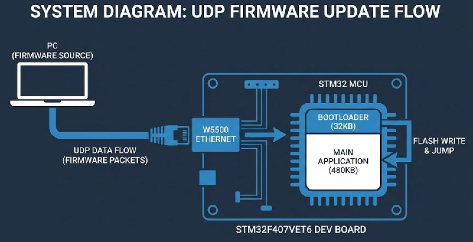
This is a complete, self-contained OTA update mechanism with handshaking and integrity verification — all in C, no third-party middleware.
2. Who Built This — and Why It Stands Out
Aleksandr Selivanov (@smalltown-boy) is an embedded developer from Saint-Petersburg, Russia who describes himself as someone who loves programming microcontrollers and grappling. That combination — methodical, precise, works well under pressure — shows in the code. The README is provided in both English and Russian, which reflects the kind of developer who thinks about who else might use their work.
The repository has 7 release tags, which is unusually thorough for a solo project of this scope. Each tag represents a deliberate milestone in the development, not just incremental commits. That discipline around versioning suggests someone building something meant to be used in real projects, not just pushed to GitHub and forgotten.
3. The Bootloader Architecture — Flash Memory Layout
The project enforces a clean memory split between the bootloader and the user application:
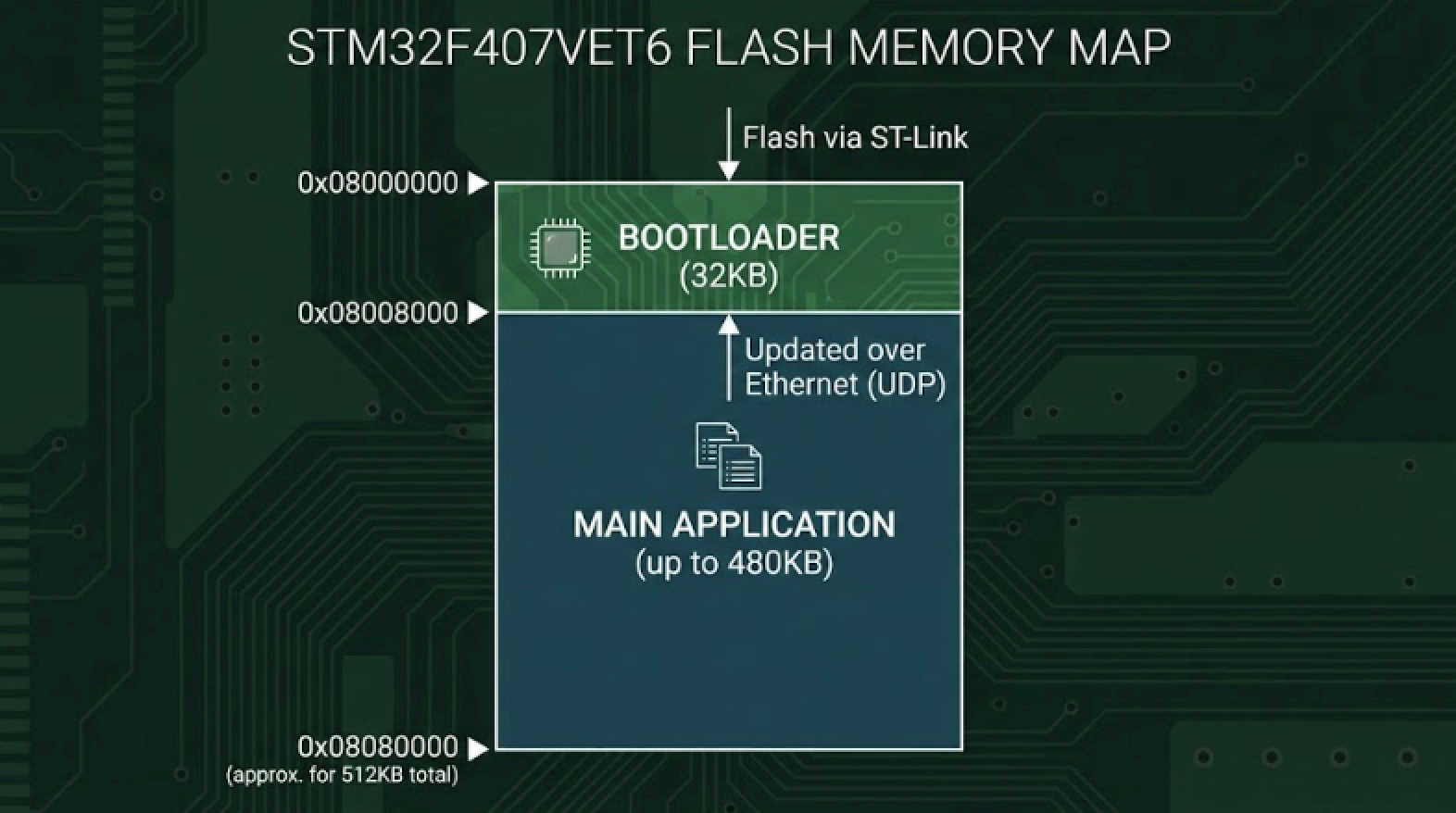
The bootloader claims only the first 32KB, leaving 480KB free for the application. The user's linker script and interrupt vector table must be configured to start at 0x08008000 — a well-known embedded requirement that the README explicitly calls out.
4. Why W5500 Is the Right Choice for a Bootloader
A bootloader has one job: be small, reliable, and get out of the way. That's exactly why the W5500's hardwired TCP/IP stack is a better fit here than any software-based networking solution.
| Requirement | Why W5500 Delivers |
|---|---|
| Small footprint | TCP/IP stack lives in W5500 hardware, not MCU Flash |
| Reliability | Hardwired stack has no heap allocation, no dynamic memory issues |
| Simple SPI interface | Only 5 wires between MCU and W5500 |
| UDP support | Native, hardware-accelerated — no protocol overhead in the bootloader |
| 3.3V compatibility | Direct connection to STM32F407, no level shifters |
Running UDP (instead of TCP) keeps the bootloader protocol stateless and simple — no connection management, no ACK handling at the transport level. The application protocol above UDP handles handshaking with explicit command bytes (0xAA, 0xBB, 0xCC, 0xDD) and a CRC integrity check, so reliability is handled at the right layer.
5. W5500 Wiring
| STM32F407VET6 Pin | W5500 Pin | Function |
|---|---|---|
| PB15 | MOSI | SPI data out |
| PB14 | MISO | SPI data in |
| PB13 | SCK | SPI clock |
| PB12 | CS | Chip select |
| PD0 | RST | Hardware reset |
SPI2 on the STM32F407 is used here — a deliberate choice that keeps the Ethernet interface on its own dedicated peripheral, separate from any application SPI busses.
6. The Update Protocol in Detail
The protocol is minimal by design — exactly what a bootloader should be.
Phase 1 — Synchronization
| PC Sends | Bootloader Responds | Meaning |
|---|---|---|
0xAA | 0xBB | Flash erased, ready for firmware |
0xAA | 0xCC | Erase failed, retry |
0xDD | 0xBB | Erase only, no firmware expected |
Phase 2 — Firmware Transmission
Firmware is sent in 1024-byte chunks with a 4-byte header:
[ 0x01 | 0xFF | DATA_LEN_H | DATA_LEN_L | DATA (1024 bytes) ]
  header  code   length MSB   length LSB   payload
Phase 3 — CRC Verification
[ 0x01 | 0xEE | CRC_H | CRC_L ]
header code checksum bytes| Response | Meaning |
|---|---|
0xE2 | CRC match — update successful, jumping to main app |
0xE1 | CRC mismatch — update failed, waiting for retry |
0xE0 | Unknown error |
The CRC check is the safety net that prevents a corrupted binary from being jumped into. If the checksum doesn't match, the bootloader stays in waiting state — the device remains recoverable.
7. Network Configuration
Bootloader IP:   10.0.28.60
Subnet Mask:     255.255.0.0
Port:            5555
Protocol:        UDP
The PC and the target device must be on the same subnet (10.0.x.x). No DHCP, no DNS — static addressing keeps the bootloader simple and deterministic.
FAQ
Q1: Why UDP instead of TCP for firmware transfer? UDP keeps the bootloader code smaller and removes the need for TCP connection state management. Reliability is handled at the application protocol level via explicit handshake bytes and a CRC checksum — which gives you the integrity guarantees that matter, without the overhead of a full TCP stack in the bootloader.
Q2: What happens if the firmware transfer is interrupted mid-way? If the CRC check at the end fails (response 0xE1), the bootloader returns to the sync byte waiting state. The device doesn't jump to the main application, so it stays in bootloader mode and can receive another attempt. The old firmware has already been erased at step 1, so interrupted transfers mean the device stays in recovery mode until a successful update completes.
Q3: How do I trigger bootloader mode? Pull pin PB1 to ground on startup. In normal operation (PB1 floating or high), the bootloader checks the pin and jumps directly to the main application at 0x08008000.
Q4: What does the main application linker script need to specify? The main application must set its flash origin to 0x08008000 in the linker script, and must relocate the interrupt vector table to that address. Without the vector table relocation, interrupt handlers in the main application won't work correctly after the bootloader hands off control.
Q5: How large can the main firmware be? Up to 480KB. The bootloader occupies the first 32KB of the 512KB Flash, leaving 480KB for the application.
Q6: Can I adapt this to a different STM32 variant? The project is built with STM32CubeIDE v1.19.0 and uses the STM32 HAL. The W5500 wiring and protocol are hardware-agnostic, so adaptation to other STM32F4 variants mainly requires adjusting the linker scripts, Flash sector sizes for erasure, and possibly the SPI peripheral assignment.
Q7: Does this work on a production board or only on dev boards? The README describes a complete standalone bootloader with static IP, SWD initial flash, and UDP-based update — this is exactly the pattern used in real production environments where devices are deployed and updated remotely. It's not a demo; it's a working starting point for a production OTA flow.