
Arduino W5500 Rotary Light Control for Home Assistant
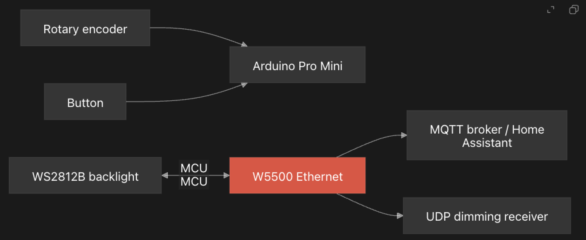
Arduino Pro Mini uses W5500 Ethernet for MQTT light state and UDP dimming control.
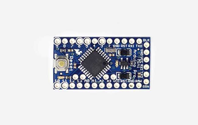
Arduino - Arduino Pro Mini
x 1

WIZnet - W5500
x 1

platformio - PlatformIO IDE
x 1

Arduino - Arduino IDE
x 1
Arduino Pro Mini and W5500 on a Static LAN
The build configuration is a compact PlatformIO project. platformio.ini targets pro8MHzatmega328 with the Arduino framework and declares dependencies for Ethernet, MQTT, JSON parsing, button handling, and RGB LED output. That target choice matters because the ATmega328 is memory-constrained. The latest commit message explicitly says the author removed dynamic JSON generation and replaced it with macros to save memory.
The firmware uses a static IPv4 layout on 192.168.55.0/24. The device ID is compiled into the firmware with #define ID 239, then reused as the last byte of the MAC address and IP address. In the current code, the controller IP becomes 192.168.55.239, while both the router and MQTT broker are set to 192.168.55.1.
The public repository does not include a schematic, but the pin map is visible in src/main.cpp: the rotary encoder uses pins 2 and 3, the push button uses pin 4, the WS2812B backlight uses pin 6, and the W5500 reset line uses pin 9. An optional motion sensor path is present behind a commented PIN_IR 5.
W5500 TCP and UDP Sockets
The network initialization in src/main.cpp is concise:
EthernetClient ethClient;
EthernetUDP Udp;
PubSubClient mqtt(ethClient);

Ethernet.begin(mac, sensor_IP);
mqtt.setServer(mqtt_IP, 1883);
mqtt.setCallback(on_message);
mqtt_setup_connect();
Udp.begin(BACKLIGHT_PORT);
This is a TOE use case. The application uses the Arduino Ethernet2 abstractions, and the vendored Ethernet2 code opens W5500 hardware sockets underneath. EthernetClient.cpp creates a TCP socket with SnMR ::TCP and calls connect, while EthernetUdp2.cpp creates a UDP socket with SnMR ::UDP. The lower socket.cpp layer writes W5500 socket registers and issues commands such as open and connect.
That gives the firmware two different network behaviors. MQTT runs over TCP through PubSubClient, which is useful for configuration and state. UDP is used for rotary dimming increments because the code comments note that MQTT is too slow for pushing encoder movement.
MQTT Setup for Main, Slave, and Backlight Control
On MQTT connect, the firmware subscribes to three setup/control topics: one for a main light, one for a slave light, and one for the local backlight. Incoming JSON messages can provide a light ID, state topic, set topic, and UDP port. The small Light class then stores those values for later button and encoder actions.
A short button press toggles the main light by publishing {"state":"ON"} or {"state":"OFF"} to the configured set topic. A long press toggles the slave light in the same style. When state messages arrive from either light's state topic, the firmware updates its local Light object with state and brightness.
The backlight path is separate. With DATA_PIN enabled, the firmware publishes a retained Home Assistant discovery-style payload for an RGB light using compile-time topic macros. Incoming backlight JSON can update RGB values and brightness, and FastLED writes those values to the eight WS2812B LEDs. One source-level caveat is that the current STR(x) macro expands to an empty string, so a reusable version should check the topic names before deployment.
UDP Packets for Rotary Dimming
The rotary encoder interrupt accumulates light_increment. In the main loop, when the increment exceeds the threshold, the firmware sends a seven-byte UDP packet. The packet includes the device ID, the active light's unique ID, and a signed increment value. If the main light is on, the packet goes to the main light's configured UDP port. If the slave light is on, it goes to the slave light's configured port.
This is a practical design choice for a physical dimmer. MQTT is good for state and integration, but it can be heavy for rapid turn-by-turn brightness adjustment. A small UDP packet keeps the rotary feel responsive while MQTT still carries the slower configuration and state synchronization work.
Repository Limits and Reuse Notes
LightRotarySensor is best presented as a personal smart home firmware, not as a polished hardware reference design. There is no top-level README, no wiring diagram, no PCB, no BOM, and no assembled hardware photo. The code also contains room-specific Russian comments and a hardcoded device ID, so another maker would need to adapt IDs, topics, IP addresses, and pin choices before reuse.
The value is still clear. It shows how a small AVR board can become a wired smart home controller when paired with a W5500. Instead of asking the microcontroller to carry a software TCP/IP stack, the firmware uses the W5500 for Ethernet sockets and spends its limited resources on encoder handling, button behavior, MQTT message parsing, and LED feedback.
FAQ
Q: What does this project use the W5500 for?
A: The W5500 provides wired Ethernet for the Arduino Pro Mini controller. The firmware uses it for MQTT over TCP and for short UDP packets that carry rotary dimming increments.
Q: Does LightRotarySensor use WIZnet TOE?
A: Yes. The application uses Ethernet2 EthernetClient and EthernetUDP, and the library opens W5500 TCP and UDP hardware sockets. The sketch does not implement TCP/IP in software.
Q: Is this a Wi-Fi and Ethernet hybrid project?
A: No. The inspected source code only initializes wired Ethernet through the W5500. There is no Wi-Fi, BLE, LoRa, Zigbee, or other wireless network path.
Q: What should be changed before reusing the firmware?
A: The device ID, IP addresses, MQTT topics, UDP receiver ports, and pin map are application-specific. The public repo also lacks a schematic, so hardware wiring must be checked against the pin constants in src/main.cpp.
Q: Why does the code use UDP for rotary movement instead of MQTT?
A: The source comment says the rotary encoder signal needs to be pushed by network UDP because MQTT is too slow for that path. MQTT remains useful for setup, state, and Home Assistant-style integration.