
STM32 Microcontroller - Input Capture, FFT Frequency Measurement
STM32 Microcontroller - Input Capture, FFT Frequency Measurement
This content describes how to add the function of acquiring the frequency of phase A voltage signal or phase B current signal in a practical project based on STM32F103VET6. It is implemented through input capture and FFT respectively, and both have been tested and are working. Continuously updated, original content is not easy to create!
I. Hardware Connection
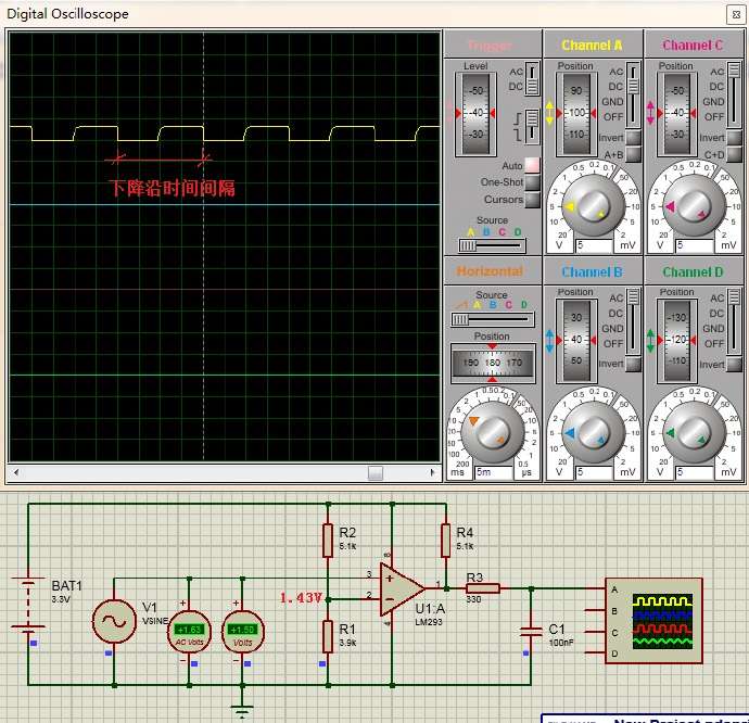
1. Voltage signal processing circuit simulation
2. Microcontroller connection
Main control MCU: STM32F103ZET6 ( Introduction to STM32 ), LM293 output connected to PB0 to detect the frequency of voltage signal, as shown in Figures 1.1.1 and 1.2.1.
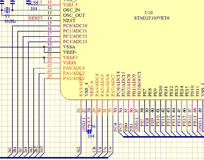
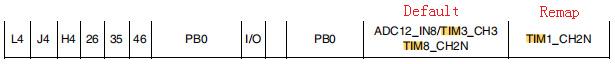
As shown in Figure 1.2.2, note that TIM3_CH2N is the PWM capture-compare output, while TIM3_CH3 is the input capture.
II. Program Section
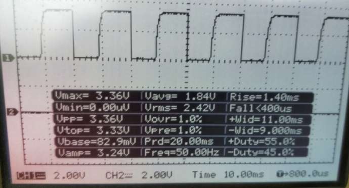
Frequency measurement is achieved through two methods: STM32 input capture and FFT conversion, both of which have been implemented in practical engineering. When the STM32 input capture signal amplitude is less than 2V, the microcontroller cannot detect the transition edge, requiring appropriate hardware processing of the signal (as shown in Figure 1.1.1). PB0/ADC8 can also read the signal voltage value using the ADC; a value of 0 is recorded, and a return to 0 indicates half a cycle has elapsed. By calculating the time difference between two ADC values reaching 0, the signal frequency can be calculated. This method is not limited by the signal amplitude.
1. Input capture via STM32
The following program acquires the voltage signal from port PB0 (Figure 1.2.1). Due to the low frequency and the requirement that the relay output time be less than 35ms, the frequency is calculated using the period measurement method. The main timer configuration and timer interrupt routines are given. Because the rising edge is not steep when tested with an oscilloscope (as can be seen in the simulation diagram in Figure 1.1.1), two falling edges of one cycle are used. Note: Subsequent processing programs must capture both falling edges before appropriate processing can be performed. Processing will fail if the acquisition program is not completed.
1) Timer Configuration
void adc_TIM_Init(void)
{
   TIM_TimeBaseInitTypeDef TIM_TimeBaseStructure; //定时器
   GPIO_InitTypeDef GPIO_InitStructure; //端口
   TIM_ICInitTypeDef TIM_ICInitStructure; //输入捕获

   //初始化GPIO口
  GPIO_InitStructure.GPIO_Mode=GPIO_Mode_IN_FLOATING; //浮空输入模式
   GPIO_InitStructure.GPIO_Pin=GPIO_Pin_0;
   GPIO_Init(GPIOB,&GPIO_InitStructure);
   GPIO_SetBits(GPIOB,GPIO_Pin_0);


   //使能时钟
   RCC_APB1PeriphClockCmd(RCC_APB1Periph_TIM3,ENABLE); //TIM3
   RCC_APB2PeriphClockCmd(RCC_APB2Periph_GPIOB|RCC_APB2Periph_AFIO,ENABLE);


   //初始化TIM3定时
   TIM_TimeBaseStructInit(&TIM_TimeBaseStructure);
   TIM_TimeBaseStructure.TIM_Prescaler = 17; //1MHz计数脉冲 1uS
   TIM_TimeBaseStructure.TIM_Period = 65535;
   TIM_TimeBaseStructure.TIM_ClockDivision = 0x0;
   TIM_TimeBaseStructure.TIM_CounterMode = TIM_CounterMode_Up; //向上计数
   TIM_TimeBaseInit(TIM3, &TIM_TimeBaseStructure);
   TIM_TimeBaseStructInit(&TIM_TimeBaseStructure);


   //初始化TIM3 Channel3输入捕获IC(Input Capture)
   TIM_ICInitStructure.TIM_Channel=TIM_Channel_3;
   TIM_ICInitStructure.TIM_ICPolarity=TIM_ICPolarity_Falling; //下降沿捕获
   TIM_ICInitStructure.TIM_ICSelection=TIM_ICSelection_DirectTI; //管脚与寄存器一一对应
   TIM_ICInitStructure.TIM_ICPrescaler=TIM_ICPSC_DIV1; //有下降沿就捕获,不分频
   TIM_ICInitStructure.TIM_ICFilter=0x00; //不打开输入捕获滤波器
   TIM_ICInit(TIM3,&TIM_ICInitStructure);

   TIM_ITConfig(TIM3,TIM_IT_Update,ENABLE); //允许定时中断
   TIM_ITConfig(TIM3,TIM_IT_CC3,ENABLE); //允许CC3捕获中断
   TIM_Cmd(TIM3,ENABLE);
…………
}
--------------------------------
2) Timer overflow and input capture interrupt handling
void TIM3_IRQHandler(void) //TIM3
{
   static u8 CapStatus=0;
//捕获状态,CapStatus=0未捕获到第1个下降沿,CapStatus=1捕获到第1个下降沿
   static u8 TIM3_CH3_Capture=0; //总的计数次数
   u32 FrequencyTemp=0;

   if(TIM_GetITStatus(TIM3,TIM_IT_Update)) //TIM3定时溢出更新中断
   {
      TIM_ClearITPendingBit(TIM3,TIM_IT_Update); //清除中断标志位
      if(CapStatus)
         TIM3_CH3_Capture++;
   }

   if(TIM_GetITStatus(TIM3,TIM_IT_CC3)) //RB0输入捕获中断
   {
      TIM_ClearITPendingBit(TIM3,TIM_IT_CC3); //清除中断标志位
      if(!CapStatus)
      {
         CapStatus=1;
         TIM_SetCounter(TIM3,0); //计数器清零
      }
      else if(CapStatus) //已经捕获到第1个下降沿
      {
         CapStatus=0;
         FrequencyTemp=TIM_GetCapture3(TIM3)+TIM3_CH3_Capture*65536;//计算两个下降沿总计数
         TIM3_CH3_Capture=0; //溢出次数清零
         TIM_SetCounter(TIM3,0); //计数器清零
         FrequencyValue=400000000/FrequencyTemp;//计算频率,比如5000,单位0.01Hz
      }
   }
}
2. Implemented via FFT
1) Overview The following describes the acquisition of the small channel current signal from PC1 port (Figure 1.2.1) and frequency calculation. The firmware implements FFT using the official ST DSP library. For the test firmware, please refer to: FFT (implemented with the official ST DSP library) .
--------------------------------
2) Data Acquisition: Data acquisition is performed using the STM32F103's built-in 12-bit ADC. A timer triggers the ADC acquisition, and DMA is used for data transfer. The timer duration is set manually, and the sampling frequency is known. For related content, please refer to: ADC Conversion Summary (Sampling Principle, Averaging, Accuracy, etc.) .
--------------------------------
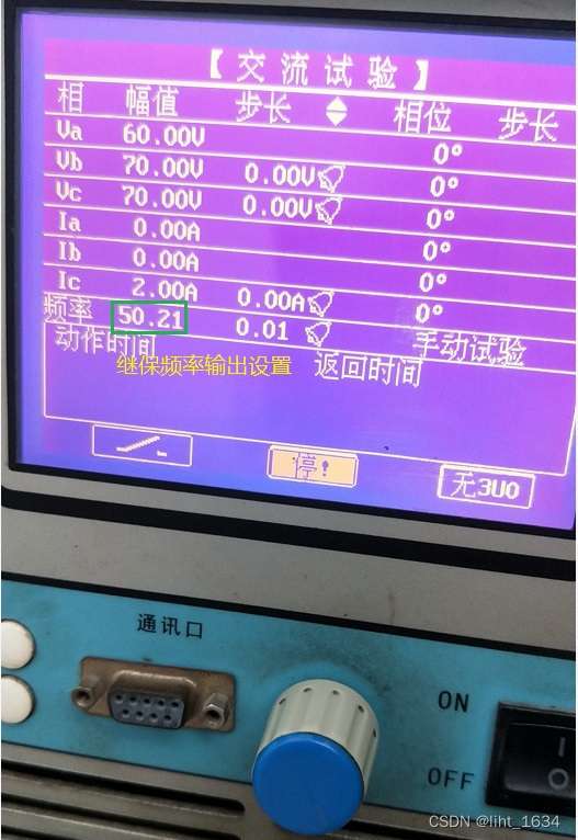
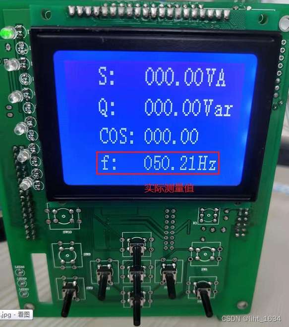
3) Function Introduction: FFT can accurately measure voltage, current, active power, reactive power, frequency, harmonic components (e.g., displaying 2nd to 32nd harmonics), and phase angle (the angle between voltage and current). The secondary values of the current transformer are accurate to two decimal places without difficulty. It has a wide current range, with hardware added for both large and small channels and separate program acquisition. Inrush current has the highest second harmonic content, thus enabling second harmonic suppression. For related information, please refer to: Power - Inrush Current Suppression and Harmonics .

Three-stage protection step: Relay protection principle 1.1 - Current and direction protection , reverse step: Relay protection principle 1.2 - Inverse time overcurrent protection .
-----------------
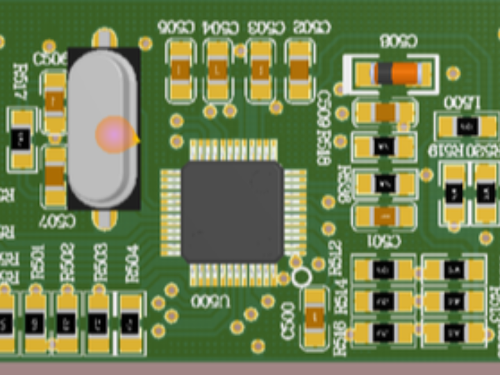
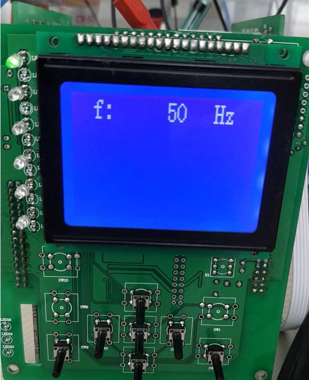
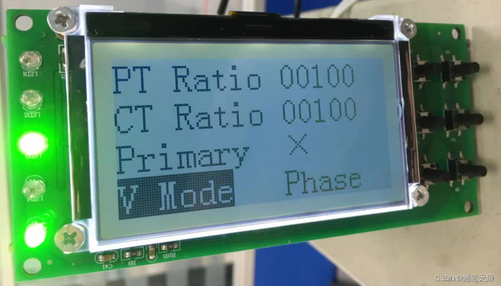
Control board that has implemented FFT:
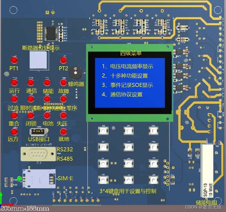 Figure 2.2.2 Front view of the main control board
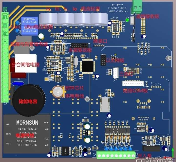
-----------------
For an introduction to GSM SMS functionality, please refer to: SIM7600CE Module (GSM/GPRS) Debugging .


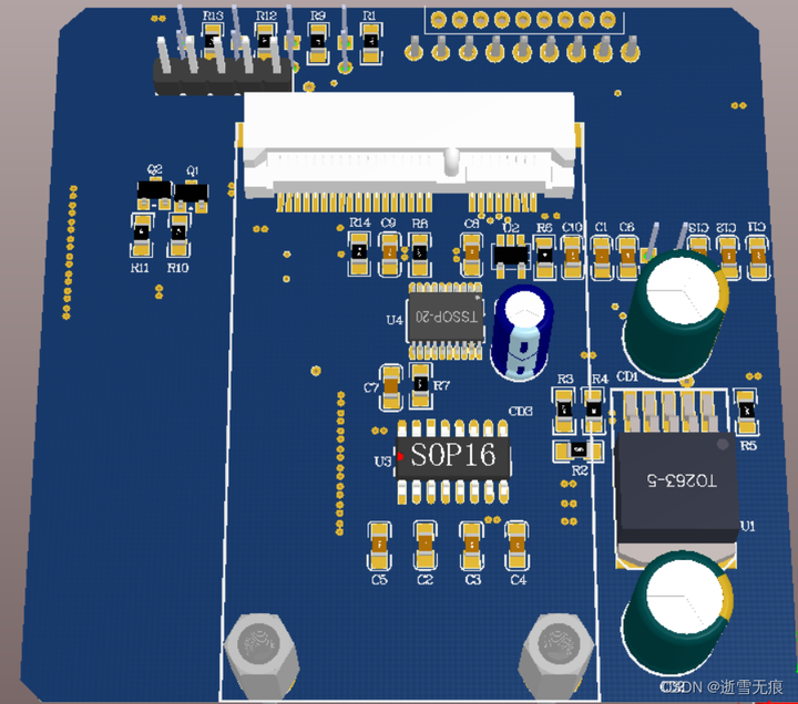
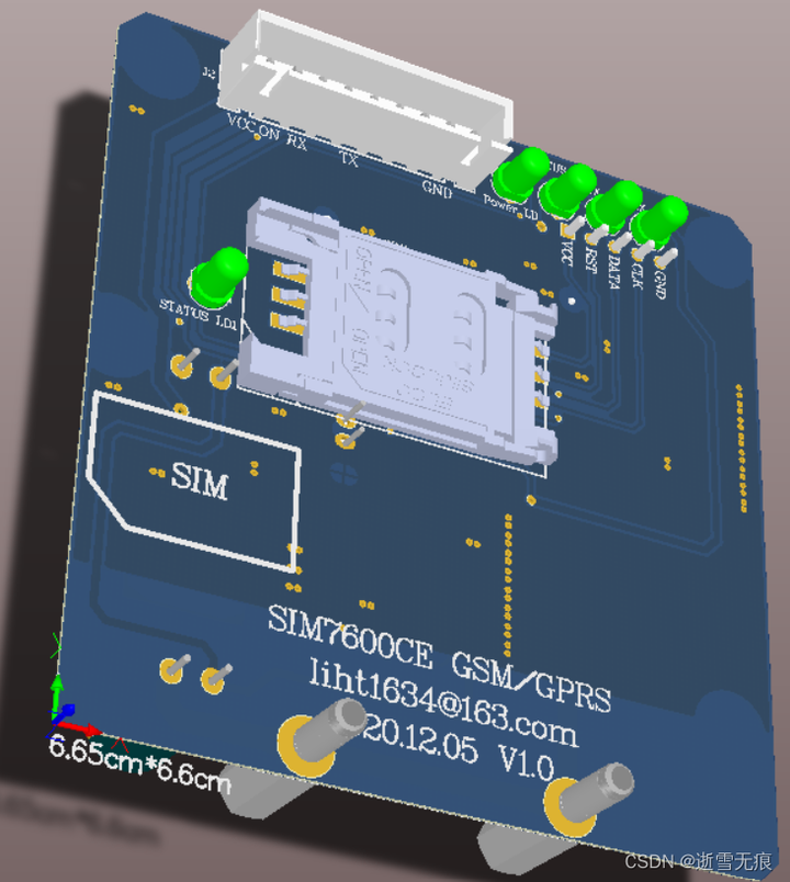
 Figure 2.2.4 4G SMS test board
-----------------
For an introduction to GPRS data functionality, please refer to: The STM32-GPRS module connects to the system master station and can use Inhand industrial data terminals for transparent transmission.
-----------------
Ethernet function board. This solution is based on W5500. For a detailed introduction, please refer to: Network Knowledge Summary (based on W5500 Ethernet) .
3. Introduction to Display Drivers
Please refer to: 12864 LCD Display Principle (C Code) .
Appendix 1: Frequency Calculation Method
The information was found online and its accuracy is not guaranteed. It has not been actually tested and is for reference only. The frequency can be calculated by counting the number of rising or falling edges within a certain time period. Frequency = Number of rising or falling edges / Statistical time.
-----------------------------------------------------------
Method 1: Utilize external interrupts to count the number of edge jumps, and configure a timer to calculate the frequency at regular intervals. Partial code is shown below.
void exti_init()  //外部中断初始化函数
{
    GPIO_InitTypeDef GPIO_InitStructure;
    EXTI_InitTypeDef EXTI_InitStructure;
    NVIC_InitTypeDef NVIC_InitStructure;

    RCC_APB2PeriphClockCmd(RCC_APB2Periph_AFIO,ENABLE);
    RCC_APB2PeriphClockCmd(RCC_APB2Periph_GPIOC,ENABLE);

    GPIO_InitStructure.GPIO_Pin=GPIO_Pin_2;
    GPIO_InitStructure.GPIO_Mode=GPIO_Mode_IN_FLOATING;
    GPIO_InitStructure.GPIO_Speed=GPIO_Speed_50MHz;
    GPIO_Init(GPIOC,&GPIO_InitStructure);

    GPIO_EXTILineConfig(GPIO_PortSourceGPIOC, GPIO_PinSource2);
//选择GPIO引脚用作外部中段线路
//此处一定要记住给端口管脚加上中断外部线路

    EXTI_InitStructure.EXTI_Line=EXTI_Line2;
    EXTI_InitStructure.EXTI_Mode=EXTI_Mode_Interrupt;
    EXTI_InitStructure.EXTI_Trigger=EXTI_Trigger_Falling;  //下降沿进中断
    EXTI_InitStructure.EXTI_LineCmd = ENABLE;
    EXTI_Init(&EXTI_InitStructure);


    NVIC_PriorityGroupConfig(NVIC_PriorityGroup_1);
    NVIC_InitStructure.NVIC_IRQChannel = EXTI2_IRQn; //打开EXTI2的全局中断
    NVIC_InitStructure.NVIC_IRQChannelPreemptionPriority = 1; //设置优先级
    NVIC_InitStructure.NVIC_IRQChannelSubPriority = 1;
    NVIC_InitStructure.NVIC_IRQChannelCmd = ENABLE;   //使能
    NVIC_Init(&NVIC_InitStructure);
}
External interrupt function:
void EXTI2_IRQHandler()
{
    if(EXTI_GetITStatus(EXTI_Line2)==SET)
    {
        EXTI_ClearITPendingBit(EXTI_Line0);//清中断
        if(GPIO_ReadInputDataBit(GPIOC,GPIO_Pin_2)==Bit_RESET)    //确定沿
        {
            cnt++;
        }
    }
}
Timer interrupt function:
void TIM3_IRQHandler()
{

    frequent=cnt; //定时器设置时间为1s时
    cnt=0;  //清零计数cnt
    TIM_ClearITPendingBit(TIM3,TIM_IT_Update);    //清标志位
}
-----------------------------------------------------------
Method 2: Use an external timer for counting. Another timer is responsible for calculating the frequency at regular intervals. Part of the code is shown below.
void time_init()
{
    GPIO_InitTypeDef GPIO_InitStructure;
    TIM_TimeBaseInitTypeDef TIM2_TimeBaseInitStructure;
    TIM_TimeBaseInitTypeDef TIM3_TimeBaseInitStructure;
    NVIC_InitTypeDef NVIC_InitStructure;

    RCC_APB2PeriphClockCmd(RCC_APB2Periph_GPIOA,ENABLE);
    RCC_APB1PeriphClockCmd(RCC_APB1Periph_TIM3,ENABLE);
    RCC_APB1PeriphClockCmd(RCC_APB1Periph_TIM2,ENABLE);

    GPIO_InitStructure.GPIO_Pin=GPIO_Pin_0;
    GPIO_InitStructure.GPIO_Mode=GPIO_Mode_IPU;
    GPIO_InitStructure.GPIO_Speed=GPIO_Speed_50MHz;
    GPIO_Init(GPIOA,&GPIO_InitStructure);
    TIM_ClearITPendingBit(TIM2,TIM_IT_Update);//清除TIM2中断标志位
    TIM2_TimeBaseInitStructure.TIM_Period = 0xFFFF;//设置自动重装载值
    TIM2_TimeBaseInitStructure.TIM_Prescaler = 0;//设置分频
    TIM2_TimeBaseInitStructure.TIM_ClockDivision = TIM_CKD_DIV1;
    TIM2_TimeBaseInitStructure.TIM_CounterMode = TIM_CounterMode_Up;//向上计数
    TIM_TimeBaseInit(TIM2,&TIM2_TimeBaseInitStructure);

    TIM_ETRClockMode1Config(TIM2, TIM_ExtTRGPSC_OFF,TIM_ExtTRGPolarity_NonInverted, 0x00);  //设置为采用外部时钟计数,可设定滤波参数消除信号干扰
    TIM_Cmd(TIM2,ENABLE);
    TIM_ClearITPendingBit(TIM3,TIM_IT_Update);
    TIM3_TimeBaseInitStructure.TIM_Period = 999;
    TIM3_TimeBaseInitStructure.TIM_Prescaler = 3599;
    TIM3_TimeBaseInitStructure.TIM_ClockDivision = TIM_CKD_DIV1;
    TIM3_TimeBaseInitStructure.TIM_CounterMode = TIM_CounterMode_Up;
    TIM_TimeBaseInit(TIM3,&TIM3_TimeBaseInitStructure);
    TIM_Cmd(TIM3,ENABLE);
    TIM_ITConfig(TIM3, TIM_IT_Update, ENABLE );
    NVIC_PriorityGroupConfig(NVIC_PriorityGroup_1);
    NVIC_InitStructure.NVIC_IRQChannel=TIM3_IRQn;
    NVIC_InitStructure.NVIC_IRQChannelPreemptionPriority=0;
    NVIC_InitStructure.NVIC_IRQChannelSubPriority=0;
    NVIC_InitStructure.NVIC_IRQChannelCmd = ENABLE;
    NVIC_Init(&NVIC_InitStructure);
}
Timer interrupt function:
void TIM3_IRQHandler()
{
    static u8 i;
    static u32 frequent_sum;
    TIM_ClearITPendingBit(TIM3,TIM_IT_Update);   //清中断

    if(i<19)
    {
        cnt += TIM_GetCounter(TIM2);  //,获取计数器的值,累加减少误差
        TIM_SetCounter(TIM2,0);    //计数器清零
        i++;
    }
    else
    {
        cnt += TIM_GetCounter(TIM2);
        TIM_SetCounter(TIM2,0);
        cnt += cnt*0.000025; //根据实际情况修改系数线性补偿
        frequent = cnt;
        i = 0;
        cnt = 0;
    }
}
---------------------------------------------------------------------------------------------
If you like this, please give it a thumbs up! Follow me for more helpful tips and updates!
Originality Statement: This article is authorized by the author for publication on the Tencent Cloud Developer Community. It may not be reproduced without permission.
If there is any copyright infringement, please contact cloudcommunity@tencent.com for removal.