
Sharing W5500 example programs
Sharing W5500 example programs
/**************************************************************************************
* Filename: W5500.c
* Description: W5500 driver library
* Library version: ST_v3.5
* Taobao: http://yixindianzikeji.taobao.com/
**************************************************************************************/
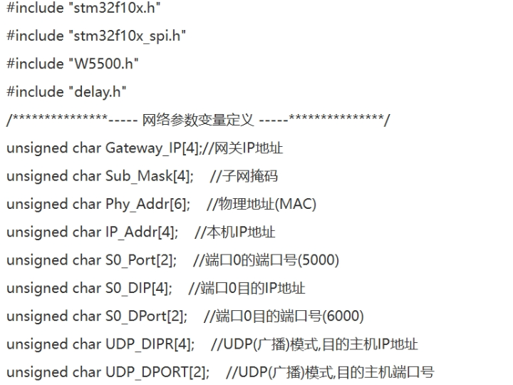
#include "stm32f10x.h"
#include "stm32f10x_spi.h"
#include "W5500.h"
#include "delay.h"
/***************----- Network Parameter Variable Definitions-----***************/
unsigned char Gateway_IP[4];// Gateway IP address
unsigned char Sub_Mask[4]; // Subnet mask
unsigned char Phy_Addr[6]; // Physical address (MAC)
unsigned char IP_Addr[4]; // Local IP address
unsigned char S0_Port[2]; // Port number of port 0 (5000)
unsigned char S0_DIP[4]; // Destination IP address of port 0
unsigned char S0_DPort[2]; // Destination port number of port 0 (6000)
unsigned char UDP_DIPR[4]; //UDP (broadcast) mode, destination host IP address
unsigned char UDP_DPORT[2]; //UDP (broadcast) mode, destination host port number
/***************----- Port Operating Modes-----***************/
unsigned char S0_Mode =3; // Operating modes of port 0, 0: TCP server mode, 1: TCP client mode, 2: UDP (broadcast) mode
#define TCP_SERVER 0x00 // TCP server mode
#define TCP_CLIENT 0x01 // TCP client mode
#define UDP_MODE 0x02 // UDP (broadcast) mode
/***************----- Port running status-----***************/
unsigned char S0_State = 0x00; // Port 0 status record, 1: Port initialization complete, 2: Port connection complete (can transmit data normally)
#define S_INIT 0x01 // Port initialization complete
#define S_CONN 0x02 // Port connection complete, can transmit data normally
/***************----- Port data transmission and reception status-----***************/
unsigned char S0_Data=0x00; // Port 0's data transmission and reception status, 1: Port received data, 2: Port completed sending data
#define S_RECEIVE 0x01 // Port received a data packet
#define S_TRANSMITOK 0x02 // Port completed sending a data packet
/***************----- Port Data Buffer -----***************/
unsigned char Rx_Buffer[2048]; // Port receive data buffer
unsigned char Tx_Buffer[2048]; // Port send data buffer
unsigned char W5500_Interrupt; //W5500 interrupt flag (0: no interrupt, 1: interrupt present)
/*******************************************************************************
* Function Name: W5500_GPIO_Configuration
* Description: W5500 GPIO initialization configuration
* Input: None
* Output: None
* Return Value: None
* Description: None
**********************************************************************************/
void W5500_GPIO_Configuration(void)
{
GPIO_InitTypeDef GPIO_InitStructure;
EXTI_InitTypeDef EXTI_InitStructure;
/* W5500_RST pin initialization configuration (PC5) */
GPIO_InitStructure.GPIO_Pin = W5500_RST; //pin 5
GPIO_InitStructure.GPIO_Speed=GPIO_Speed_10MHz; //speed 10MHz
GPIO_InitStructure.GPIO_Mode = GPIO_Mode_Out_PP; //push-pull output
GPIO_Init(W5500_RST_PORT, &GPIO_InitStructure); //PC
GPIO_ResetBits(W5500_RST_PORT, W5500_RST); //default PC5 is low
/* W5500_INT pin initialization configuration (PC4) */
GPIO_InitStructure.GPIO_Pin = W5500_INT;
GPIO_InitStructure.GPIO_Speed=GPIO_Speed_50MHz;
GPIO_InitStructure.GPIO_Mode = GPIO_Mode_IPU;
GPIO_Init(W5500_INT_PORT, &GPIO_InitStructure);
/* Connect EXTI Line4 to PC4 */
GPIO_EXTILineConfig(GPIO_PortSourceGPIOC, GPIO_PinSource4);
/* PC4 as W5500 interrupt input */
EXTI_InitStructure.EXTI_Line = EXTI_Line4;
EXTI_InitStructure.EXTI_Mode = EXTI_Mode_Interrupt;
EXTI_InitStructure.EXTI_Trigger = EXTI_Trigger_Falling;
EXTI_InitStructure.EXTI_LineCmd = ENABLE;
EXTI_Init(&EXTI_InitStructure);
}
/*******************************************************************************
* Function Name: W5500_NVIC_Configuration
* Description: W5500 Receive Pin Interrupt Priority Setting
* Input: None
* Output: None
* Return Value: None
* Description: None
**********************************************************************************/
void W5500_NVIC_Configuration(void)
{
NVIC_InitTypeDef NVIC_InitStructure;
/* Enable the EXTI4 Interrupt */
NVIC_InitStructure.NVIC_IRQChannel = EXTI4_IRQn;
NVIC_InitStructure.NVIC_IRQChannelPreemptionPriority = 0;
NVIC_InitStructure.NVIC_IRQChannelSubPriority = 1;
NVIC_InitStructure.NVIC_IRQChannelCmd = ENABLE;
NVIC_Init(&NVIC_InitStructure);
}
/*******************************************************************************
* Function Name: EXTI4_IRQHandler
* Description: Interrupt service function for interrupt line 4 (W5500 INT pin interrupt service function)
* Input: None
* Output: None
* Return Value: None
* Note: None
**********************************************************************************/
void EXTI4_IRQHandler(void)
{
if(EXTI_GetITStatus(EXTI_Line4) != RESET)
{
EXTI_ClearITPendingBit(EXTI_Line4);
W5500_Interrupt=1;
}
}
/***************************************************************************
* Function Name: SPI_Configuration
* Description: W5500 SPI initialization configuration (STM32 SPI1)
* Input: None
* Output: None
* Return Value: None
* Description: None
**********************************************************************************/
void SPI_Configuration(void)
{
GPIO_InitTypeDef GPIO_InitStructure;
SPI_InitTypeDef SPI_InitStructure;
RCC_APB2PeriphClockCmd(RCC_APB2Periph_GPIOA | RCC_APB2Periph_SPI1 | RCC_APB2Periph_AFIO, ENABLE);
/* Initialize SCK, MISO, MOSI pins*/
GPIO_InitStructure.GPIO_Pin = GPIO_Pin_5 | GPIO_Pin_6 | GPIO_Pin_7;
GPIO_InitStructure.GPIO_Speed = GPIO_Speed_50MHz;
GPIO_InitStructure.GPIO_Mode = GPIO_Mode_AF_PP; //Multiplex push-pull PA5,6,7
GPIO_Init(GPIOA, &GPIO_InitStructure);
GPIO_SetBits(GPIOA,GPIO_Pin_5|GPIO_Pin_6|GPIO_Pin_7);
/* Initialize CS pin*/
GPIO_InitStructure.GPIO_Pin = W5500_SCS;
GPIO_InitStructure.GPIO_Speed=GPIO_Speed_50MHz;
GPIO_InitStructure.GPIO_Mode=GPIO_Mode_Out_PP;
GPIO_Init(W5500_SCS_PORT, &GPIO_InitStructure);
GPIO_SetBits(W5500_SCS_PORT, W5500_SCS);
/* Initialize and configure STM32 SPI1 */
SPI_InitStructure.SPI_Direction=SPI_Direction_2Lines_FullDuplex; // Set SPI to two-wire bidirectional full-duplex
SPI_InitStructure.SPI_Mode=SPI_Mode_Master; // Set to master SPI
SPI_InitStructure.SPI_DataSize=SPI_DataSize_8b; // SPI transmit/receive 8-bit frame structure
SPI_InitStructure.SPI_CPOL=SPI_CPOL_Low; // Clock floating low
SPI_InitStructure.SPI_CPHA=SPI_CPHA_1Edge; // Data captured on the first clock edge
SPI_InitStructure.SPI_NSS=SPI_NSS_Soft; // NSS is managed by an external pin
SPI_InitStructure.SPI_BaudRatePrescaler=SPI_BaudRatePrescaler_2; // Baud rate prescaler value is 2
SPI_InitStructure.SPI_FirstBit = SPI_FirstBit_MSB; // Data transmission starts from the MSB bit.
SPI_InitStructure.SPI_CRCPolynomial = 7; // CRC polynomial is 7.
SPI_Init(SPI1, &SPI_InitStructure); // Initialize peripheral SPI1 register according to the parameters specified in SPI_InitStructure.
SPI_Cmd(SPI1,ENABLE); // Enable SPI1 on
STM32
/*******************************************************************************
* Function Name: SPI1_Send_Byte
* Description: Sends 1 byte of data using SPI1
* Input: dat: Data to be sent
* Output: None
* Return Value: None
* Notes: None
**********************************************************************************/
void SPI1_Send_Byte(unsigned char dat)
{
SPI_I2S_SendData(SPI1,dat);//Write 1 byte of data
while(SPI_I2S_GetFlagStatus(SPI1, SPI_I2S_FLAG_TXE) == RESET);//Wait for the data register to be empty
}
/*******************************************************************************
* Function Name: SPI1_Send_Short
* Description: Sends 2 bytes (16 bits) of data using SPI1
* Input: dat: 16 bits of data to be sent
* Output: None
* Return Value: None
* Notes: None
**********************************************************************************/
void SPI1_Send_Short(unsigned short dat)
{
SPI1_Send_Byte(dat/256);//Write the high-order bits
SPI1_Send_Byte(dat); //Write the low-order bits
}
/*******************************************************************************
* Function Name: Write_W5500_1Byte
* Description: Writes 1 byte of data to a specified address register via SPI1
* Input: reg: 16-bit register address, dat: data to be written
* Output: None
* Return Value: None
* Notes: None
**********************************************************************************/
void Write_W5500_1Byte(unsigned short reg, unsigned char dat)
{
GPIO_ResetBits(W5500_SCS_PORT, W5500_SCS);//Sets W5500's SCS to low level PA4
SPI1_Send_Short(reg); // Writes a 16-bit register address via SPI1
SPI1_Send_Byte(FDM1|RWB_WRITE|COMMON_R); // Writes a control byte via SPI1, 1 byte of data length, writes data, selects a general-purpose register
SPI1_Send_Byte(dat); // Writes 1 byte of data
GPIO_SetBits(W5500_SCS_PORT, W5500_SCS); // Sets the SCS pin of the W5500 to high
.
/*******************************************************************************
* Function Name: Write_W5500_2Byte
* Description: Writes 2 bytes of data to a specified address register via SPI1
* Input: reg: 16-bit register address, dat: 16-bit data to be written (2 bytes)
* Output: None
* Return Value: None
* Description: None
**********************************************************************************/
void Write_W5500_2Byte(unsigned short reg, unsigned short dat)
{
GPIO_ResetBits(W5500_SCS_PORT, W5500_SCS); // Sets the SCS of W5500 to low level.
SPI1_Send_Short(reg); // Writes a 16-bit register address via SPI1.
SPI1_Send_Byte(FDM2|RWB_WRITE|COMMON_R); // Writes a control byte via SPI1, 2 bytes of data length, writes data, and selects a general-purpose register.
SPI1_Send_Short(dat); // Writes 16-bit data.
GPIO_SetBits(W5500_SCS_PORT, W5500_SCS); // Sets the SCS pin of the W5500 to high
.
/*******************************************************************************
* Function Name: Write_W5500_nByte
* Description: Writes n bytes of data to a specified address register via SPI1
* Input: reg: 16-bit register address, *dat_ptr: pointer to the data buffer to be written, size: length of data to be written
* Output: None
* Return Value: None
* Description: None
**********************************************************************************/
void Write_W5500_nByte(unsigned short reg, unsigned char *dat_ptr, unsigned short size)
{
unsigned short i;
GPIO_ResetBits(W5500_SCS_PORT, W5500_SCS); // Sets the SCS of W5500 to low level.
SPI1_Send_Short(reg); // Writes a 16-bit register address via SPI1.
SPI1_Send_Byte(VDM|RWB_WRITE|COMMON_R); // Writes a control byte via SPI1, N bytes of data length, writes data, and selects a general-purpose register.
for(i=0;i<size;i++) // Loop through and write size bytes of data from the buffer to the W5500
{
SPI1_Send_Byte(*dat_ptr++); // Write one byte of data
}
GPIO_SetBits(W5500_SCS_PORT, W5500_SCS); // Sets the SCS pin of the W5500 to high
.
/*******************************************************************************
* Function Name: Write_W5500_SOCK_1Byte
* Description: Writes 1 byte of data to the specified port register via SPI1
* Input: s: port number, reg: 16-bit register address, dat: data to be written
* Output: None
* Return Value: None
* Description: None
**********************************************************************************/
void Write_W5500_SOCK_1Byte(SOCKET s, unsigned short reg, unsigned char dat)
{
GPIO_ResetBits(W5500_SCS_PORT, W5500_SCS); // Sets the SCS of W5500 to low level.
SPI1_Send_Short(reg); // Writes a 16-bit register address via SPI1
. SPI1_Send_Byte(FDM1|RWB_WRITE|(s*0x20+0x08)); // Writes a control byte via SPI1, 1 byte of data length, writes data, selects the register of port s.
SPI1_Send_Byte(dat); // Writes 1 byte of data.
GPIO_SetBits(W5500_SCS_PORT, W5500_SCS); // Sets the SCS pin of the W5500 to high
.
/*******************************************************************************
* Function Name: Write_W5500_SOCK_2Byte
* Description: Writes 2 bytes of data to the specified port register via SPI1
* Input: s: port number, reg: 16-bit register address, dat: 16-bit data to be written (2 bytes)
* Output: None
* Return Value: None
* Description: None
**********************************************************************************/
void Write_W5500_SOCK_2Byte(SOCKET s, unsigned short reg, unsigned short dat)
{
GPIO_ResetBits(W5500_SCS_PORT, W5500_SCS); // Sets the SCS of W5500 to low level.
SPI1_Send_Short(reg); // Writes a 16-bit register address via SPI1
. SPI1_Send_Byte(FDM2|RWB_WRITE|(s*0x20+0x08)); // Writes a control byte via SPI1, 2 bytes of data length, writes the data, and selects the register of port s.
SPI1_Send_Short(dat); // Writes 16-bit data.
GPIO_SetBits(W5500_SCS_PORT, W5500_SCS); // Sets the SCS pin of the W5500 to high
.
/*******************************************************************************
* Function Name: Write_W5500_SOCK_4Byte
* Description: Writes 4 bytes of data to the specified port register via SPI1
* Input: s: port number, reg: 16-bit register address, *dat_ptr: pointer to the 4-byte buffer to be written
* Output: None
* Return Value: None
* Description: None
**********************************************************************************/
void Write_W5500_SOCK_4Byte(SOCKET s, unsigned short reg, unsigned char *dat_ptr)
{
GPIO_ResetBits(W5500_SCS_PORT, W5500_SCS); // Sets the SCS of W5500 to low level.
SPI1_Send_Short(reg); // Writes a 16-bit register address via SPI1
. SPI1_Send_Byte(FDM4|RWB_WRITE|(s*0x20+0x08)); // Writes a control byte via SPI1, 4 bytes of data length, writes the data, and selects the register of port s.
SPI1_Send_Byte(*dat_ptr++); // Write the first byte of data
SPI1_Send_Byte(*dat_ptr++); // Write the second byte of data
SPI1_Send_Byte(*dat_ptr++); // Write the third byte of data
SPI1_Send_Byte(*dat_ptr++); // Write the fourth byte of data
GPIO_SetBits(W5500_SCS_PORT, W5500_SCS); // Sets the SCS pin of the W5500 to high
.
/*******************************************************************************
* Function Name: Read_W5500_1Byte
* Description: Reads 1 byte of data from the W5500 register at the specified address
* Input: reg: 16-bit register address
* Output: None
* Return Value: 1 byte of data read from the register
* Notes: None
**********************************************************************************/
unsigned char Read_W5500_1Byte(unsigned short reg)
{
unsigned char i;
GPIO_ResetBits(W5500_SCS_PORT, W5500_SCS); // Sets the SCS of W5500 to low level.
SPI1_Send_Short(reg); // Writes a 16-bit register address via SPI1
. SPI1_Send_Byte(FDM1|RWB_READ|COMMON_R); // Writes a control byte via SPI1, reads data, and selects a general-purpose register.
i = SPI_I2S_ReceiveData(SPI1);
SPI1_Send_Byte(0x00); // Send a dummy data
i = SPI_I2S_ReceiveData(SPI1); // Read 1 byte of data
GPIO_SetBits(W5500_SCS_PORT, W5500_SCS); // Sets the SCS of W5500 to high level
return i; // Returns the read register
data
/*******************************************************************************
* Function Name: Read_W5500_SOCK_1Byte
* Description: Reads 1 byte of data from the specified port register of W5500
* Input: s: port number, reg: 16-bit register address
* Output: None
* Return Value: 1 byte of data read from the register
* Notes: None
**********************************************************************************/
unsigned char Read_W5500_SOCK_1Byte(SOCKET s, unsigned short reg)
{
unsigned char i;
GPIO_ResetBits(W5500_SCS_PORT, W5500_SCS); // Sets the SCS of W5500 to low level.
SPI1_Send_Short(reg); // Writes a 16-bit register address via SPI1.
SPI1_Send_Byte(FDM1|RWB_READ|(s*0x20+0x08)); // Writes a control byte via SPI1, 1 byte of data length, reads data, and selects the register of port s.
i = SPI_I2S_ReceiveData(SPI1);
SPI1_Send_Byte(0x00); // Send a dummy data
i = SPI_I2S_ReceiveData(SPI1); // Read 1 byte of data
GPIO_SetBits(W5500_SCS_PORT, W5500_SCS); // Sets the SCS of W5500 to high level
return i; // Returns the read register
data
/*******************************************************************************
* Function Name: Read_W5500_SOCK_2Byte
* Description: Reads 2 bytes of data from the specified port register of W5500
* Input: s: port number, reg: 16-bit register address
* Output: None
* Return Value: 2 bytes (16 bits) of data read from the register
* Notes: None
**********************************************************************************/
unsigned short Read_W5500_SOCK_2Byte(SOCKET s, unsigned short reg)
{
unsigned short i;
GPIO_ResetBits(W5500_SCS_PORT, W5500_SCS); // Sets the SCS of W5500 to low level.
SPI1_Send_Short(reg); // Writes a 16-bit register address via SPI1.
SPI1_Send_Byte(FDM2|RWB_READ|(s*0x20+0x08)); // Writes a control byte via SPI1, 2 bytes of data length, reads data, and selects the register of port s.
i = SPI_I2S_ReceiveData(SPI1);
SPI1_Send_Byte(0x00); // Send a dummy data
i = SPI_I2S_ReceiveData(SPI1); // Read the high-order data
SPI1_Send_Byte(0x00); // Send a dummy data
i *= 256;
i += SPI_I2S_ReceiveData(SPI1); // Read the low-order data
GPIO_SetBits(W5500_SCS_PORT, W5500_SCS); // Sets the SCS of W5500 to high level
return i; // Returns the read register
data
/*******************************************************************************
* Function Name: Read_SOCK_Data_Buffer
* Description: Reads data from the W5500 receive data buffer
* Input: s: Port number, *dat_ptr: Pointer to the data storage buffer
* Output: None
* Return Value: Length of data read, rx_size bytes
* Note: None
**********************************************************************************/
unsigned short Read_SOCK_Data_Buffer(SOCKET s, unsigned char *dat_ptr)
{
unsigned short rx_size;
unsigned short offset, offset1;
unsigned short i;
unsigned char j;
rx_size = Read_W5500_SOCK_2Byte(s, Sn_RX_RSR);
if (rx_size == 0) return 0; // Return if no data is received
if (rx_size > 1460) rx_size = 1460;
offset = Read_W5500_SOCK_2Byte(s, Sn_RX_RD);
offset1 = offset;
offset &= (S_RX_SIZE - 1); // Calculate the actual physical address
GPIO_ResetBits(W5500_SCS_PORT, W5500_SCS); // Sets the SCS bit of W5500 to low.
SPI1_Send_Short(offset); // Write 16-bit address
SPI1_Send_Byte(VDM|RWB_READ|(s*0x20+0x18)); // Write control byte, N bytes of data length, read data, select register of port s
j=SPI_I2S_ReceiveData(SPI1);
if((offset+rx_size)<S_RX_SIZE) // If the maximum address does not exceed the maximum address of the W5500 receive buffer register
{
for(i=0;i<rx_size;i++) // Loop to read rx_size bytes of data
{
SPI1_Send_Byte(0x00); // Send a dummy data
j=SPI_I2S_ReceiveData(SPI1); // Read 1 byte of data
*dat_ptr=j; // Save the read data to the data storage buffer
dat_ptr++; // Increment the address of the data storage buffer
}
}
else // If the maximum address exceeds the maximum address of the W5500 receive buffer register
{
offset = S_RX_SIZE - offset;
for (i = 0; i < offset; i++) // Loop through and read the first offset bytes of data
{
SPI1_Send_Byte(0x00); // Send a dummy data
j = SPI_I2S_ReceiveData(SPI1); // Read 1 byte of data
* dat_ptr = j; // Save the read data to the data storage buffer
dat_ptr++; // Increment the address of the data storage buffer pointer by 1
}
GPIO_SetBits(W5500_SCS_PORT, W5500_SCS); // Set the SCS of the W5500 to high level
GPIO_ResetBits(W5500_SCS_PORT, W5500_SCS); // Sets the SCS bit of W5500 to low.
SPI1_Send_Short(0x00); // Write 16-bit address
SPI1_Send_Byte(VDM|RWB_READ|(s*0x20+0x18)); // Write control byte, N bytes of data length, read data, select register j of port s
j=SPI_I2S_ReceiveData(SPI1);
for(;i<rx_size;i++)//Read rx_size-offset bytes of data in a loop
{
SPI1_Send_Byte(0x00);//Send a dummy data
j=SPI_I2S_ReceiveData(SPI1);//Read 1 byte of data
*dat_ptr=j;//Save the read data to the data storage buffer
dat_ptr++;//Increment the address of the data storage buffer pointer by 1
}
}
GPIO_SetBits(W5500_SCS_PORT, W5500_SCS); //Set the SCS of W5500 to high level
offset1 += rx_size; // Update the actual physical address, i.e., the starting address of the next read of received data.
Write_W5500_SOCK_2Byte(s, Sn_RX_RD, offset1);
Write_W5500_SOCK_1Byte(s, Sn_CR, RECV); // Send the command to start receiving.
return rx_size; // Return the length of the received data
.
/*******************************************************************************
* Function Name: Write_SOCK_Data_Buffer
* Description: Writes data to the W5500's data transmission buffer
* Input: s: port number, *dat_ptr: pointer to the data storage buffer, size: length of data to be written
* Output: None
* Return Value: None
* Description: None
**********************************************************************************/
void Write_SOCK_Data_Buffer(SOCKET s, unsigned char *dat_ptr, unsigned short size)
{
unsigned short offset, offset1;
unsigned short i;
//If it is UDP mode, you can set the destination host IP and port number here.
if((Read_W5500_SOCK_1Byte(s,Sn_MR)&0x0f) != SOCK_UDP) //If the socket fails to open
, {
Write_W5500_SOCK_4Byte(s, Sn_DIPR, UDP_DIPR); //Set the destination host IP
Write_W5500_SOCK_2Byte(s, Sn_DPORTR, UDP_DPORT[0]*256+UDP_DPORT[1]); //Set the destination host port number
}
offset = Read_W5500_SOCK_2Byte(s, Sn_TX_WR);
offset1 = offset;
offset &= (S_TX_SIZE - 1); // Calculate the actual physical address
GPIO_ResetBits(W5500_SCS_PORT, W5500_SCS); // Sets the SCS bit of W5500 to low.
SPI1_Send_Short(offset); // Write 16-bit address
SPI1_Send_Byte(VDM|RWB_WRITE|(s*0x20+0x10)); // Write control byte, N bytes of data length, write data, select port s register
if ((offset + size) < S_TX_SIZE) // If the maximum address does not exceed the maximum address of the W5500 transmit buffer register
{
for (i = 0; i < size; i++) // Loop through and write size bytes of data
{
SPI1_Send_Byte(*dat_ptr++); // Write one byte of data
}
}
else // If the maximum address exceeds the maximum address of the W5500 transmit buffer register
{
offset = S_TX_SIZE - offset;
for (i = 0; i < offset; i++) // Loop through and write the first offset bytes of data
{
SPI1_Send_Byte(*dat_ptr++); // Write one byte of data
}
GPIO_SetBits(W5500_SCS_PORT, W5500_SCS); // Set the SCS of the W5500 to high level
GPIO_ResetBits(W5500_SCS_PORT, W5500_SCS); // Sets the SCS bit of W5500 to low.
SPI1_Send_Short(0x00); // Write 16-bit address
SPI1_Send_Byte(VDM|RWB_WRITE|(s*0x20+0x10)); // Write control byte, N bytes of data length, write data, select port s register
for(;i<size;i++)//Loop to write size-offset bytes of data
{
SPI1_Send_Byte(*dat_ptr++);//Write one byte of data
}
}
GPIO_SetBits(W5500_SCS_PORT, W5500_SCS); //Set W5500's SCS to high level
offset1 += size; // Update the actual physical address, i.e., the starting address for the next write of data to be sent to the transmit data buffer.
Write_W5500_SOCK_2Byte(s, Sn_TX_WR, offset1);
Write_W5500_SOCK_1Byte(s, Sn_CR, SEND); // Send the start command
.
/*******************************************************************************
* Function Name: W5500_Hardware_Reset
* Description: Hardware reset of W5500
* Input: None
* Output: None
* Return Value: None
* Note: The W5500 reset pin must be held low for at least 500µs to reset the W5500.
*******************************************************************************/
void W5500_Hardware_Reset(void)
{
GPIO_ResetBits(W5500_RST_PORT, W5500_RST);//Reset pin pulled low
delay_ms(100);
GPIO_SetBits(W5500_RST_PORT, W5500_RST);//Reset pin pulled high
delay_ms(200);
while((Read_W5500_1Byte(PHYCFGR)&LINK)==0);//Wait for Ethernet connection to complete
}
/*******************************************************************************
* Function Name: W5500_Init
* Description: Function to initialize the W5500 registers
* Input: None
* Output: None
* Return Value: None
* Note: Before using the W5500, initialize it first
******************************************************************************/
void W5500_Init(void)
{
u8 i=0;
Write_W5500_1Byte(MR, RST); // Software reset W5500, sets it to 1 for validity, automatically clears it to 0 after reset.
delay_ms(20); // Delay 10ms, this function is user-defined.
// Set the gateway's IP address. Gateway_IP is a 4-byte unsigned char array, user-defined.
// Using a gateway allows communication to bypass subnet limitations, enabling access to other subnets or the Internet.
Write_W5500_nByte(GAR, Gateway_IP, 4);
// Set the subnet mask value. SUB_MASK is a 4-byte unsigned char array, user-defined.
// The subnet mask is used for subnet calculations.
Write_W5500_nByte(SUBR, Sub_Mask, 4);
// Set the physical address. PHY_ADDR is a 6-byte unsigned char array, user-defined, used to uniquely identify the network device's physical address.
// This address value needs to be obtained from IEEE. According to OUI specifications, the first 3 bytes are the manufacturer code, and the last 3 bytes are the product serial number
. // If you define the physical address yourself, note that the first byte must be an even number.
Write_W5500_nByte(SHAR, Phy_Addr, 6);
// Set the local machine's IP address. IP_ADDR is a 4-byte unsigned char array, which you can define yourself.
// Note that the gateway IP must belong to the same subnet as the local machine's IP; otherwise, the local machine will not be able to find the gateway.
Write_W5500_nByte(SIPR, IP_Addr, 4);
// Set the size of the transmit and receive buffers, refer to the W5500 datasheet.
for(i=0;i<8;i++)
{
Write_W5500_SOCK_1Byte(i, Sn_RXBUF_SIZE, 0x02); // Socket Rx memory size = 2k
Write_W5500_SOCK_1Byte(i, Sn_TXBUF_SIZE, 0x02); // Socket Tx memory size = 2k
}
// Sets the retry time, default is 2000 (200ms)
// Each unit value is 100 microseconds, initialized to 2000 (0x07D0), equal to 200 milliseconds
Write_W5500_2Byte(RTR, 0x07d0);
//Set the number of retries, the default is 8 times.//If
the number of retries exceeds the set value, a timeout interrupt will be generated (the Sn_IR timeout bit (TIMEOUT) in the relevant port interrupt register will be set to "1")
. Write_W5500_1Byte(RCR,8);
//Enable interrupts. Refer to the W5500 datasheet to determine the required interrupt type.//IMR_CONFLICT
is an IP address conflict exception interrupt; IMR_UNREACH is a UDP communication address unreachable exception interrupt.//Others
are Socket event interrupts. Add them as needed.
Write_W5500_1Byte(IMR,IM_IR7 | IM_IR6);
Write_W5500_1Byte(SIMR,S0_IMR);
Write_W5500_SOCK_1Byte(0, Sn_IMR, IMR_SENDOK | IMR_TIMEOUT | IMR_RECV | IMR_DISCON | IMR_CON);
}
/*******************************************************************************
* Function Name: Detect_Gateway
* Description: Check gateway server
* Input: None
* Output: None
* Return Value: Returns TRUE (0xFF) on success, FALSE (0x00) on failure
* Note: None
**********************************************************************************/
unsigned char Detect_Gateway(void)
{
unsigned char ip_adde[4];
ip_adde[0]=IP_Addr[0]+1;
ip_adde[1]=IP_Addr[1]+1;
ip_adde[2]=IP_Addr[2]+1;
ip_adde[3]=IP_Addr[3]+1;
// Check the gateway and get its physical address
Write_W5500_SOCK_4Byte(0,Sn_DIPR,ip_adde); // Write an IP value different from the local IP to the destination address register
Write_W5500_SOCK_1Byte(0,Sn_MR,MR_TCP); // Set the socket to TCP mode
Write_W5500_SOCK_1Byte(0,Sn_CR,OPEN); // Open the socket
delay_ms(5); // Delay for 5ms
if(Read_W5500_SOCK_1Byte(0,Sn_SR) != SOCK_INIT) // If the socket opening fails
{
Write_W5500_SOCK_1Byte(0,Sn_CR,CLOSE); // If the opening fails, close the socket
return FALSE; // Return FALSE(0x00)
}
Write_W5500_SOCK_1Byte(0,Sn_CR,CONNECT); // Set the socket to Connect mode.
do
{
u8 j=0;
j=Read_W5500_SOCK_1Byte(0,Sn_IR);//Read Socket0 interrupt flag register
if(j!=0)
Write_W5500_SOCK_1Byte(0,Sn_IR,j);
delay_ms(5);//Delay 5ms
if((j&IR_TIMEOUT) == IR_TIMEOUT)
{
return FALSE;
}
else if(Read_W5500_SOCK_1Byte(0,Sn_DHAR) != 0xff)
{
Write_W5500_SOCK_1Byte(0,Sn_CR,CLOSE);//Close Socket
return TRUE;
}
}while(1);
}
/*******************************************************************************
* Function Name: Socket_Init
* Description: Initializes a specified Socket (0~7)
* Input: s: the port to be initialized
* Output: None
* Return Value: None
* Note: None
**********************************************************************************/
void Socket_Init(SOCKET s)
{
// Set the fragment length, refer to the W5500 datasheet, this value can be left unchanged
Write_W5500_SOCK_2Byte(0, Sn_MSSR, 1460);// Maximum fragment bytes = 1460 (0x5b4)
// Set the specified port
switch(s)
{
case 0:
// Set the port number of port 0
Write_W5500_SOCK_2Byte(0, Sn_PORT, S0_Port[0]*256+S0_Port[1]);
// Set the destination (remote) port number for port 0
Write_W5500_SOCK_2Byte(0, Sn_DPORTR, S0_DPort[0]*256+S0_DPort[1]);
// Set the destination (remote) IP address for port 0
Write_W5500_SOCK_4Byte(0, Sn_DIPR, S0_DIP);
break;
case 1:
break;
case 2:
break;
case 3:
break;
case 4:
break;
case 5:
break;
case 6:
break;
case 7:
break;
default:
break;
}
}
/*******************************************************************************
* Function Name: Socket_Connect
* Description: Sets a specified Socket (0~7) as a client to connect to a remote server.
* Input: s: The port to be set.
* Output: None.
* Return Value: Returns TRUE (0xFF) on success, FALSE (0x00) on failure.
* Note: When the local Socket is working in client mode, this program is used to establish a connection with the remote server.
* If a timeout occurs after starting the connection, the connection with the server fails, and the program needs to be called again to connect.
* Each time this program is called, a connection is established with the server.
***********************************************************************************/
unsigned char Socket_Connect(SOCKET s)
{
Write_W5500_SOCK_1Byte(s,Sn_MR,MR_TCP); // Set socket to TCP mode
Write_W5500_SOCK_1Byte(s,Sn_CR,OPEN); // Open socket
delay_ms(5); // Delay 5ms
if(Read_W5500_SOCK_1Byte(s,Sn_SR)!=SOCK_INIT) // If socket opening fails
{
Write_W5500_SOCK_1Byte(s,Sn_CR,CLOSE); // Close socket if opening fails
return FALSE; // Returns FALSE(0x00)
}
Write_W5500_SOCK_1Byte(s,Sn_CR,CONNECT); // Set socket to Connect mode
return TRUE; // Returns TRUE, setting successful
}
/*******************************************************************************
* Function Name: Socket_Listen
* Description: Sets a specified Socket (0~7) as a server to wait for connections from remote hosts.
* Input: s: The port to be set.
* Output: None.
* Return Value: Returns TRUE (0xFF) on success, FALSE (0x00) on failure.
* Note: When the local Socket is working in server mode, this program is used to wait for connections from remote hosts.
* This program is called only once to set the W5500 to server mode.
***********************************************************************************/
unsigned char Socket_Listen(SOCKET s)
{
Write_W5500_SOCK_1Byte(s,Sn_MR,MR_TCP);//Set the socket to TCP mode
Write_W5500_SOCK_1Byte(s,Sn_CR,OPEN);//Open the Socket
delay_ms(5); // Delay 5ms
if (Read_W5500_SOCK_1Byte(s,Sn_SR)!=SOCK_INIT) // If socket opening fails
{
Write_W5500_SOCK_1Byte(s,Sn_CR,CLOSE); // If opening fails, close the socket
return FALSE; // Returns FALSE(0x00)
}
Write_W5500_SOCK_1Byte(s,Sn_CR,LISTEN); // Set the socket to listen mode
delay_ms(5); // Delay 5ms
if (Read_W5500_SOCK_1Byte(s,Sn_SR)!=SOCK_LISTEN) // If socket setting fails
{
Write_W5500_SOCK_1Byte(s,Sn_CR,CLOSE); // If setting fails, close the socket
return FALSE; // Returns FALSE(0x00)
}
return TRUE;
//This completes the opening and setting up of the socket for listening. Whether the remote client establishes a connection depends on whether the socket is interrupted,
//to determine if the connection was successful. Refer to the W5500 datasheet for socket interrupt status.
//In server listening mode, it is not necessary to set the destination IP and destination port number
.}
/*******************************************************************************
* Function Name: Socket_UDP
* Description: Sets the specified Socket (0~7) to UDP mode
* Input: s: The port to be set
* Output: None
* Return Value: Returns TRUE (0xFF) on success, FALSE (0x00) on failure
* Note: If the Socket is working in UDP mode, using this program will allow Socket communication without establishing a connection in UDP mode.
* This program is called only once to set the W5500 to UDP mode.
***********************************************************************************/
unsigned char Socket_UDP(SOCKET s)
{
Write_W5500_SOCK_1Byte(s,Sn_MR,MR_UDP);//Set the Socket to UDP mode*/
Write_W5500_SOCK_1Byte(s,Sn_CR,OPEN);//Open the Socket*/
delay_ms(5); // Delay 5ms
if(Read_W5500_SOCK_1Byte(s,Sn_SR)!=SOCK_UDP) // If the socket opening fails
{
Write_W5500_SOCK_1Byte(s,Sn_CR,CLOSE); // If the opening fails, close the socket
return FALSE; // Return FALSE(0x00)
}
else
return TRUE;
//This completes the opening of the socket and the UDP mode setup. In this mode, it does not need to establish a connection with the remote host.//Because
the socket does not need to establish a connection, the destination host IP and the destination socket port number can be set before sending data.//If
the destination host IP and the destination socket port number are fixed and do not change during operation, they can also be set here
.}
/*******************************************************************************
* Function Name: W5500_Interrupt_Process
* Description: W5500 interrupt handler framework
* Input: None
* Output: None
* Return Value: None
* Description: None
**********************************************************************************/
void W5500_Interrupt_Process(void)
{
unsigned char i,j;
IntDispose:
W5500_Interrupt=0; // Clear the interrupt flag
i = Read_W5500_1Byte(IR); // Read the interrupt flag register
Write_W5500_1Byte(IR, (i&0xf0)); // Write back to clear the interrupt flag
if ((i & CONFLICT) == CONFLICT) // Handle IP address conflict exceptions
{
// Add your own code
}
if((i & UNREACH) == UNREACH) // Handling exceptions for addresses not reaching in UDP mode
{
// Add your own code
}
i = Read_W5500_1Byte(SIR); // Read the port interrupt flag register
if ((i & S0_INT) == S0_INT) // Socket0 event handling
{
j = Read_W5500_SOCK_1Byte(0, Sn_IR); // Read the Socket0 interrupt flag register
Write_W5500_SOCK_1Byte(0, Sn_IR, j);
if (j & IR_CON) // In TCP mode, Socket0 successfully connected
{
S0_State |= S_CONN; // Network connection status 0x02, port connection completed, data can be transmitted normally
}
if (j & IR_DISCON) // In TCP mode, Socket disconnection handling
{
Write_W5500_SOCK_1Byte(0, Sn_CR, CLOSE); // Close the port, wait to reopen the connection
Socket_Init(0); // Specify Socket (0~7) initialization, initialize port 0
S0_State = 0; // Network connection status 0x00, port connection failed
}
if(j&IR_SEND_OK) // Socket 0 data transmission complete, S_tx_process() function can be started again to send data
{
S0_Data|=S_TRANSMITOK; // Port has completed sending one data packet
}
if(j&IR_RECV) // Socket has received data, S_rx_process() function can be started
{
S0_Data|=S_RECEIVE; // Port has received one data packet
}
if(j&IR_TIMEOUT) // Socket connection or data transmission timeout handling
{
Write_W5500_SOCK_1Byte(0,Sn_CR,CLOSE); // Close port, wait to reopen connection
S0_State=0; // Network connection status 0x00, port connection failed
}
}
if(Read_W5500_1Byte(SIR) != 0)
goto IntDispose;
}
#ifndef _W5500_H_
#define _W5500_H_
/********************** Common Register *******************/
#define MR 0x0000
#define RST 0x80
#define WOL 0x20
#define PB 0x10
#define PPP 0x08
#define FARP 0x02
#define GAR 0x0001
#define SUBR 0x0005
#define SHAR 0x0009
#define SIPR 0x000f
#define INTLEVEL 0x0013
#define IR 0x0015
#define CONFLICT 0x80
#define UNREACH 0x40
#define PPPOE 0x20
#define MP 0x10
#define IMR 0x0016
#define IM_IR7 0x80
#define IM_IR6 0x40
#define IM_IR5 0x20
#define IM_IR4 0x10
#define SIR 0x0017
#define S7_INT 0x80
#define S6_INT 0x40
#define S5_INT 0x20
#define S4_INT 0x10
#define S3_INT 0x08
#define S2_INT 0x04
#define S1_INT 0x02
#define S0_INT 0x01
#define SIMR 0x0018
#define S7_IMR 0x80
#define S6_IMR 0x40
#define S5_IMR 0x20
#define S4_IMR 0x10
#define S3_IMR 0x08
#define S2_IMR 0x04
#define S1_IMR 0x02
#define S0_IMR 0x01
#define RTR 0x0019
#define RCR 0x001b
#define PTIMER 0x001c
#define PMAGIC 0x001d
#define PHA 0x001e
#define PSID 0x0024
#define PMRU 0x0026
#define UIPR 0x0028
#define UPORT 0x002c
#define PHYCFGR 0x002e
#define RST_PHY 0x80
#define OPMODE 0x40
#define DPX 0x04
#define SPD 0x02
#define LINK 0x01
#define VERR 0x0039
/************************ Socket Register *******************/
#define Sn_MR 0x0000
#define MULTI_MFEN 0x80
#define BCASTB 0x40
#define ND_MC_MMB 0x20
#define UCASTB_MIP6B 0x10
#define MR_CLOSE 0x00
#define MR_TCP 0x01
#define MR_UDP 0x02
#define MR_MACRAW 0x04
#define Sn_CR 0x0001
#define OPEN 0x01
#define LISTEN 0x02
#define CONNECT 0x04
#define DISCON 0x08
#define CLOSE 0x10
#define SEND 0x20
#define SEND_MAC 0x21
#define SEND_KEEP 0x22
#define RECV 0x40
#define Sn_IR 0x0002
#define IR_SEND_OK 0x10
#define IR_TIMEOUT 0x08
#define IR_RECV 0x04
#define IR_DISCON 0x02
#define IR_CON 0x01
#define Sn_SR 0x0003
#define SOCK_CLOSED 0x00
#define SOCK_INIT 0x13
#define SOCK_LISTEN 0x14
#define SOCK_ESTABLISHED 0x17
#define SOCK_CLOSE_WAIT 0x1c
#define SOCK_UDP 0x22
#define SOCK_MACRAW 0x02
#define SOCK_SYNSEND 0x15
#define SOCK_SYNRECV 0x16
#define SOCK_FIN_WAI 0x18
#define SOCK_CLOSING 0x1a
#define SOCK_TIME_WAIT 0x1b
#define SOCK_LAST_ACK 0x1d
#define Sn_PORT 0x0004
#define Sn_DHAR 0x0006
#define Sn_DIPR 0x000c
#define Sn_DPORTR 0x0010
#define Sn_MSSR 0x0012
#define Sn_TOS 0x0015
#define Sn_TTL 0x0016
#define Sn_RXBUF_SIZE 0x001e
#define Sn_TXBUF_SIZE 0x001f
#define Sn_TX_FSR 0x0020
#define Sn_TX_RD 0x0022
#define Sn_TX_WR 0x0024
#define Sn_RX_RSR 0x0026
#define Sn_RX_RD 0x0028
#define Sn_RX_WR 0x002a
#define Sn_IMR 0x002c
#define IMR_SENDOK 0x10
#define IMR_TIMEOUT 0x08
#define IMR_RECV 0x04
#define IMR_DISCON 0x02
#define IMR_CON 0x01
#define Sn_FRAG 0x002d
#define Sn_KPALVTR 0x002f
/******************************************************************/
/************************ SPI Control Byte *************************/
/************************************************************************/
/* Operation mode bits */
#define VDM 0x00
#define FDM1 0x01
#define FDM2 0x02
#define FDM4 0x03
/* Read_Write control bit */
#define RWB_READ 0x00
#define RWB_WRITE 0x04
/* Block select bits */
#define COMMON_R 0x00
/* Socket 0 */
#define S0_REG 0x08
#define S0_TX_BUF 0x10
#define S0_RX_BUF 0x18
/* Socket 1 */
#define S1_REG 0x28
#define S1_TX_BUF 0x30
#define S1_RX_BUF 0x38
/* Socket 2 */
#define S2_REG 0x48
#define S2_TX_BUF 0x50
#define S2_RX_BUF 0x58
/* Socket 3 */
#define S3_REG 0x68
#define S3_TX_BUF 0x70
#define S3_RX_BUF 0x78
/* Socket 4 */
#define S4_REG 0x88
#define S4_TX_BUF 0x90
#define S4_RX_BUF 0x98
/* Socket 5 */
#define S5_REG 0xa8
#define S5_TX_BUF 0xb0
#define S5_RX_BUF 0xb8
/* Socket 6 */
#define S6_REG 0xc8
#define S6_TX_BUF 0xd0
#define S6_RX_BUF 0xd8
/* Socket 7 */
#define S7_REG 0xe8
#define S7_TX_BUF 0xf0
#define S7_RX_BUF 0xf8
#define TRUE 0xff
#define FALSE 0x00
#define S_RX_SIZE 2048 /* Defines the size of the socket receive buffer, which can be modified according to the W5500_RMSR setting */
#define S_TX_SIZE 2048 /* Defines the size of the socket transmit buffer, which can be modified according to the W5500_TMSR setting */
/***************----- W5500 GPIO Definitions-----***************/
#define W5500_SCS GPIO_Pin_4 // Defines the CS pin of W5500
#define W5500_SCS_PORT GPIOA
#define W5500_RST GPIO_Pin_0 // Defines the RST pin of W5500
#define W5500_RST_PORT GPIOC
#define W5500_INT GPIO_Pin_1 // Defines the INT pin of W5500
#define W5500_INT_PORT GPIOC
/***************----- Network Parameter Variable Definitions-----***************/
extern unsigned char Gateway_IP[4]; // Gateway IP address
extern unsigned char Sub_Mask[4]; // Subnet mask
extern unsigned char Phy_Addr[6]; // Physical address (MAC)
extern unsigned char IP_Addr[4]; // Local IP address
extern unsigned char S0_Port[2]; // Port number of port 0 (5000)
extern unsigned char S0_DIP[4]; // Destination IP address of port 0
extern unsigned char S0_DPort[2]; // Destination port number of port 0 (6000)
extern unsigned char UDP_DIPR[4]; //UDP (broadcast) mode, destination host IP address
extern unsigned char UDP_DPORT[2]; //UDP (broadcast) mode, destination host port number
/***************----- Port Operating Modes-----***************/
extern unsigned char S0_Mode; // Operating modes of port 0, 0: TCP server mode, 1: TCP client mode, 2: UDP (broadcast) mode
#define TCP_SERVER 0x00 // TCP server mode
#define TCP_CLIENT 0x01 // TCP client mode
#define UDP_MODE 0x02 // UDP (broadcast) mode
/***************----- Port running status-----***************/
extern unsigned char S0_State; // Port 0 status record, 1: Port initialization complete, 2: Port connection complete (can transmit data normally)
#define S_INIT 0x01 // Port initialization complete
#define S_CONN 0x02 // Port connection complete, can transmit data normally
/***************----- Port data transmission and reception status-----***************/
extern unsigned char S0_Data; // Port 0's data transmission and reception status, 1: Port has received data, 2: Port has completed sending data
#define S_RECEIVE 0x01 // Port has received a data packet
#define S_TRANSMITOK 0x02 // Port has completed sending a data packet
/***************----- Port Data Buffer -----***************/
extern unsigned char Rx_Buffer[2048]; // Port receive data buffer
extern unsigned char Tx_Buffer[2048]; // Port send data buffer
extern unsigned char W5500_Interrupt; // W5500 interrupt flag (0: no interrupt, 1: interrupt present)
typedef unsigned char SOCKET; // Custom port number data type
`extern void Delay(unsigned int d);` // Delay function (ms)
`extern void W5500_GPIO_Configuration(void);` // W5500 GPIO initialization configuration `
extern void W5500_NVIC_Configuration(void);` // W5500 receive pin interrupt priority setting `
extern void SPI_Configuration(void);` // W5500 SPI initialization configuration (STM32 SPI1)
`extern void W5500_Hardware_Reset(void);` // Hardware reset of W5500 `
extern void W5500_Init(void);` // Initialize W5500 registers `
extern unsigned char Detect_Gateway(void);` // Check gateway server
`extern void Socket_Init(SOCKET s);` // Initialize specified socket (0~7) `
extern unsigned char Socket_Connect(SOCKET s)` s); // Set the specified Socket (0~7) as the client to connect to the remote server
extern unsigned char Socket_Listen(SOCKET s); // Set the specified Socket (0~7) as the server to wait for connections from the remote host
extern unsigned char Socket_UDP(SOCKET s); // Set the specified Socket (0~7) to UDP mode
extern unsigned short Read_SOCK_Data_Buffer(SOCKET s, unsigned char *dat_ptr); // Specify the Socket (0~7) for receiving data processing
extern void Write_SOCK_Data_Buffer(SOCKET s, unsigned char *dat_ptr, unsigned short size); // Specify the Socket (0~7) for sending data processing
extern void W5500_Interrupt_Process(void); // W5500 interrupt handler framework
#endif