
Remote control and data visualization via mobile app based on W55MH32 and OneNET
Remote control and data visualization via mobile app based on W55MH32 and OneNET
1. Introduction
MQTT is a lightweight communication protocol based on TCP/IP, employing a publish-subscribe model, and widely used in the Internet of Things (IoT) field.
MQTT's working principle revolves around three core components: Publishers, Brokers (also known as servers), and Subscribers. Publishers are responsible for sending messages to specific topics, while brokers receive these messages and forward them to all subscribers to that topic. This model allows asynchronous communication between devices, and devices do not need to be directly aware of each other's existence, thus reducing system complexity.
The W55MH32 is a high-performance Ethernet microcontroller from WIZnet. It uses a high-performance Arm® Cortex-M3 core with a maximum clock speed of 216MHz, and has 1024KB of FLASH and 96KB of SRAM. Of particular note is its WIZnet TCP/IP offload engine (TOE), which integrates a full hardware TCP/IP protocol stack, MAC, and PHY, and is equipped with a 32KB independent Ethernet transceiver buffer for use by 8 hardware sockets, making it a true all-in-one solution.
2. Project Environment
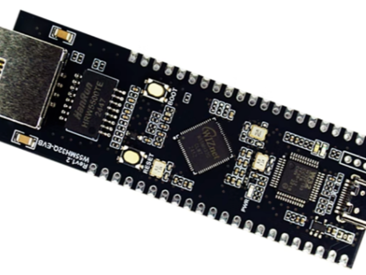
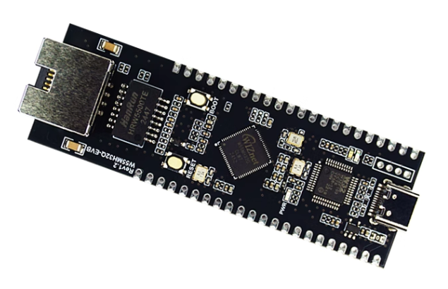
2.1 Hardware Environment
- W55MH32Q-EVB
- Network cable
- Several DuPont wires
- Switch or router
- DHT11 temperature and humidity sensor, LED light
2.2 Software Environment
- OneNET IoT Open Platform
- HBuilder X
- WIZ UartTool V1.0 Serial Port Assistant
- Example link: w5500.com/w55mh32.html
3. Hardware Connection and Solution
3.1 Solution Diagram
3.2 Hardware Connections
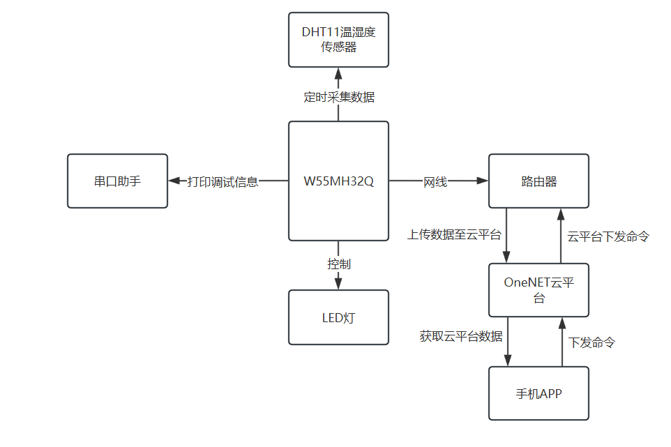
LED_Positive ---> W55MH32_GPIOA0
DHT11_OUT ---> W55MH32_GPIOA6
4. MQTT connection to OneNET cloud platform for sending and receiving data. Account registration will not be elaborated here. Next, we will see how to build the object model.
4.1 Preparation Phase
Creating Product and Additive Models: Log in to the OneNET IoT platform, create a product, and add the following additive model functions under the product.
Creating Devices: Create the corresponding devices under the product you just created.

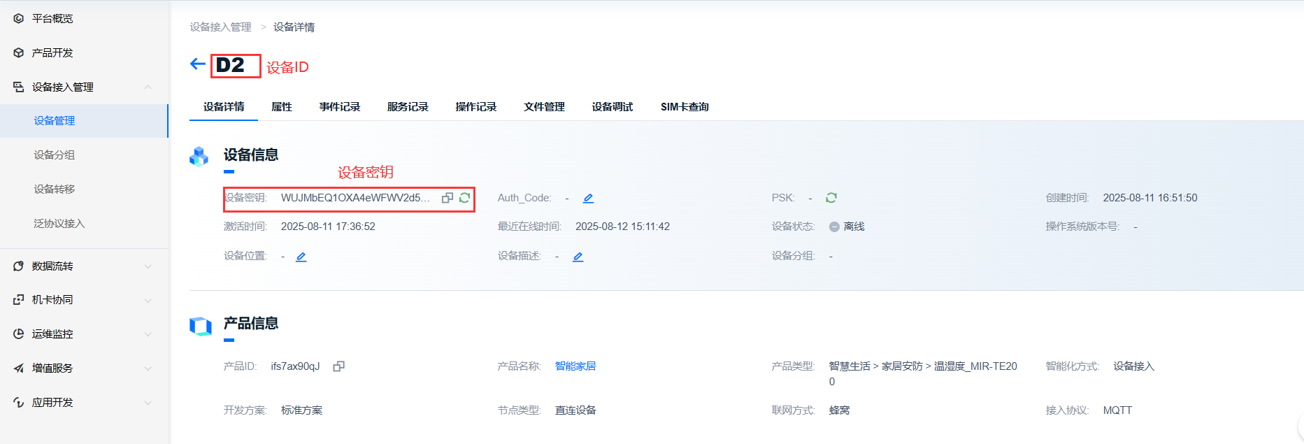
4.2 Device Details
Device Details: On the device details page, you can view important information such as the device key and device ID.
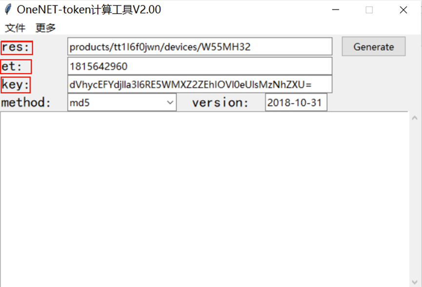
4.3 Token Key Generation
When a device communicates with the OneNet platform, a token serves as an identity credential for security authentication. A token generation tool is required:
[OneNET Token Generation Tool Documentation](Documentation Center)
1. `res` field: `products/{product id}/devices/{device name}`, where `key` is the device-level key. Replace `{product id}` with your product's ID and `{device name}` with your device's name.
2. `et` field: Enter the access expiration time. You can obtain a timestamp (Unix timestamp) conversion tool - online tool - from this website.
3. `key` field: Enter the key for your device.
4. After filling in the information, click "generate" to obtain the token key.
4.4 Connecting, Subscribing, and Publishing Messages
Subscribing to a topic: $sys/{pid}/{device-name}/thing/property/set
Subscribing to a topic response: $sys/iP20B5FpF6/d2/thing/property/set_reply
Publishing a topic: $sys/{pid}/{device-name}/thing/property/post
Publishing a topic response: $sys/iP20B5FpF6/d2/thing/property/post/reply
PID is short for product_id, i.e., the product ID.
Next, we can use the connection parameters recorded above to connect. Once the connection is successful, we subscribe to the above-mentioned topic and report the object model data through the published topic.
On the OneNET platform, if the data format selected during product creation is OneJSON, both received and sent data will adhere to the following format:
{

 "id": "123",

 "version": "1.0",

 "params": {

 "temperature":"30.5"

 }

}
id: The value is "123", which is a unique identifier; params is an object containing device attribute data used to report object model data; version: The value is "1.0", indicating the protocol version followed by the message.
5. Example Modification
5.1 MQTT Related Example Modification
Locate the do-mqtt.c file and replace the parameters mentioned above with your own OneNet parameters. These parameters have been discussed above and can be replaced as needed.
// Define and initialize the MQTT connection parameter structure
mqttconn mqtt_params = {
.mqttHostUrl = "mqtts.heclouds.com", // MQTT server URL
.server_ip = {0,}, // Server IP address (unused here, default value retained)
.port = 1883, // Connection port number, 1883 is the default unencrypted MQTT port
.clientid = "D2", // MQTT client ID, must be unique
.username = "ifs7ax90qJ", // MQTT username, usually the product ID
.passwd = "vers=md5&sign=YT2N73HSjmyy%2BbQEFMDjMw%3D%3D", // User password, including signature authentication information
.pubtopic = "$sys/ifs7ax90qJ/D2/thing/property/post", // Publish property data topic
.pubtopic_reply = "$sys/ifs7ax90qJ/D2/thing/property/post/reply", // Property data post response topic
.subtopic = "$sys/ifs7ax90qJ/D2/thing/property/set", // Subscribe to property settings topic
.subtopic_reply = "$sys/ifs7ax90qJ/D2/thing/property/set_reply", // Property settings response topic
.pubQoS = QOS0, // Quality of Service (QoS) level for publishing messages (0: at most once)
.willtopic = "/wizchip/will", // Will message topic, published when the client disconnects abnormally
.willQoS = QOS0, // QoS level for will messages
.willmsg = "wizchip offline!", // Will message content
.subQoS = QOS0, // QoS level for subscribing to messages
};
Modifications to the data reporting code: The code below contains the data and identifiers reported to the server's object model. The identifiers must match the server's object model, and the values are the data collected by the local sensors. The microcontroller processes this data and then fills in the local data variables and device status in the corresponding locations. This allows the local data to be uploaded to the server.
/**
* @brief Generates a JSON string containing sensor data and device status
*
* This function formats temperature and humidity sensor data, as well as LED pin status, into a JSON string,
for data transmission or storage. The function first performs parameter validity checks to ensure the buffer is valid and large enough. */ *
* @param json_buf [out] Pointer to the buffer used to store the generated JSON string
* @param buf_len [in] Length of the buffer in bytes
*
* @return int Result of generation: 1 for success, 0 for failure
*/ static int generate_sensor_json(char *json_buf, uint16_t buf_len) {
if (json_buf == NULL || buf_len < 256) {
return 0;
}
sprintf(json_buf,
"{\"id\":\"123\",\"version\":\"1.0\",\"params\":{"
"\"temp\":{\"value\":%d}," // Fill in temperature data
"\"humi\":{\"value\":%d}," // Fill in humidity data
"\"LED\":{\"value\":%s}" // Fill in LED status
"}}",
temp, // Temperature data variable
humi, // Humidity data variable
GPIO_ReadOutputDataBit(GPIOA, GPIO_Pin_0) ? "true" : "false");
return 1; // Returns a success status if the JSON string is successfully generated
}
Modifications to the command issuance code: To remotely control local devices, we can add code to the microcontroller to parse JSON data, and then issue commands to the server to achieve the desired effect. This code snippet parses the commands issued by the server, allowing control of the local LED based on whether the server command is to turn the light on or off. If you want to control other local devices from the server, you can add the same code as above.
/**
* @brief Parse the JSON format control commands sent from the cloud
* @param msg The JSON format string sent from the cloud
* @note This function is responsible for parsing the control commands (such as LED switches) in the JSON message,
* Execute the corresponding hardware operation, and return the processing result to the cloud
*/
void json_decode(char *msg) {
int ret; // Function return value, used to determine whether the MQTT release was successful
char replymsg[128] = {0}; // Store the JSON message replying to the cloud
cJSON *id = NULL; // The "id" field in the JSON message (used for message matching)
cJSON *jsondata = NULL; // The parsed root JSON object
cJSON *params = NULL; // The "params" field (parameter set) in the JSON message
cJSON *LED = NULL; // The "LED" control parameter in "params"
// Parse the JSON string and convert it to a cJSON object
jsondata = cJSON_Parse(msg);
if (jsondata == NULL) { // Parsing failure handling
printf("json parse fail.\r\n");
return;
}
// Extract key fields from JSON
id = cJSON_GetObjectItem(jsondata, "id"); // Get message ID (for matching in the reply)
params = cJSON_GetObjectItem(jsondata, "params"); // Get parameter object
LED = cJSON_GetObjectItem(params, "LED"); // Get LED control parameters
// Process LED control commands
if(LED->valueint) // If the LED parameter value is non-zero (usually indicating an "on" command)
{
led1_on(); // Call the LED on function
printf("led on\r\n"); // Print debug information
}
else // If the LED parameter value is 0 (usually indicating a "off" command)
{
led1_off(); // Call the LED off function
printf("led off\r\n"); // Print debug information
}
// Build and send the reply to the cloud
pubmessage.qos = QOS0; // Set the QoS level of the reply message to 0 (at most once)
/ // Format the reply message: including the original message ID, status code 200 (success), and a message
sprintf(replymsg, "{\"id\":\"%s\",\"code\":200,\"msg\":\"success\"}",
id->valuestring);
printf("reply:%s\r\n", replymsg); // Print the reply content (for debugging)
pubmessage.payload = replymsg; // Set the MQTT message payload to the reply content
pubmessage.payloadlen = strlen(replymsg); // Set the payload length
/ // Publish the reply message to the specified topic in the cloud
ret = MQTTPublish(&c, mqtt_params.subtopic_reply, &pubmessage);
if (ret != SUCCESSS) { // Publishing Failure Handling
s_run_status = MQTT_ERR; // Update system status to MQTT Error
} else { // Publishing Success Handling
printf("publish:%s,%s\r\n\r\n", mqtt_params.subtopic_reply,// Print publishing success message (for debugging)
(char *)pubmessage.payload);
}
cJSON_Delete(jsondata); // Release memory occupied by cJSON object to prevent memory leaks
}
5.2 Adding Code for Temperature and Humidity Data Acquisition
Add the humidity.c file and its .h file to achieve the purpose of acquiring temperature and humidity data. The specific code is as follows:
#include "humiture.h"
#include "delay.h"
#include "w55mh32_gpio.h"
/**
* @brief Initialize the DHT11 temperature and humidity sensor
* @return 0: Initialization successful 1: Initialization failed
*/
uint8_t DHT11_Init(void)
{
GPIO_InitTypeDef GPIO_InitStructure;
// Enable GPIOA clock
RCC_APB2PeriphClockCmd(RCC_APB2Periph_GPIOA, ENABLE);
// Configure PA6 pin as push-pull output
GPIO_InitStructure.GPIO_Pin = GPIO_Pin_6;
GPIO_InitStructure.GPIO_Mode = GPIO_Mode_Out_PP;
GPIO_InitStructure.GPIO_Speed = GPIO_Speed_50MHz;
GPIO_Init(GPIOA, &GPIO_InitStructure);
// Initialize to high level
GPIO_SetBits(GPIOA,GPIO_Pin_6);
// Send reset signal and check sensor response
DHT11_Rst();
return DHT11_Check();
}
/**
* @brief Send reset signal to DHT11
*/ void DHT11_Rst(void)
{
DHT11_IO_OUT();
// Set pin to output mode
DHT11_DQ_OUT(0);
// Pull the bus low for at least 18ms
delay_ms(20);
DHT11_DQ_OUT(1);
// Release the bus
delay_us(30);
// Wait 30us
/**
* @brief Check the DHT11 response signal
* @return 0: Response detected 1: No response detected
*/ uint8_t DHT11_Check(void)
{
uint8_t retry=0;
DHT11_IO_IN();
// Set the pin to input mode
// Wait for DHT11 to pull the bus low
while (DHT11_DQ_IN && retry < 100)
{
retry++;
delay_us(1);
};
if(retry >= 100) return 1; // Timeout without response
else retry = 0;
// Wait for DHT11 to release the bus
while (!DHT11_DQ_IN && retry < 100)
{
retry++;
delay_us(1);
};
if(retry >= 100) return 1; // Timeout without release
return 0; // Successful detection
}
/**
* @brief Read a bit from DHT11
* @return The bit value read (0 or 1)
*/ uint8_t DHT11_Read_Bit(void)
{
uint8_t retry=0;
// Wait for the bus to go high
while(DHT11_DQ_IN && retry < 100) 100)
{
retry++;
delay_us(1);
}
retry=0;
// Wait for the bus to pull low
while(!DHT11_DQ_IN && retry < 100)
{
retry++;
delay_us(1);
}
// Delay 40us to check the data bit
delay_us(40);
if(DHT11_DQ_IN) return 1;
// High level is 1
else return 0;
// Low level is 0
/**
* @brief Read a byte from DHT11
* @return The byte data read
*/ uint8_t DHT11_Read_Byte(void)
{
uint8_t i, dat;
dat = 0;
// Loop through 8 bits of data
for (i = 0; i < 8; i++)
{
dat <<= 1;
// Shift left by one bit
dat |= DHT11_Read_Bit();
// OR the bit read
}
return dat;
}
/**
* @brief Read temperature and humidity data from DHT11
* @param temp: Pointer to store temperature data
* @param humi: Pointer to store humidity data
* @return 0: Read successful 1: Read failed
*/
uint8_t DHT11_Read_Data(uint8_t *temp, uint8_t *humi)
{
uint8_t buf[5]; // Store the 5 bytes of data read
uint8_t i;
// Send a reset signal and check for a response
DHT11_Rst();
if(DHT11_Check() == 0)
{
// Read 5 bytes of data
for(i = 0; i < 5; i++)
{
buf[i] = DHT11_Read_Byte();
}
// Check data (the sum of the first 4 bytes equals the 5th byte)
if((buf[0] + buf[1] + buf[2] + buf[3]) == buf[4])
{
*humi = buf[0];
// Humidity integer part
*temp = buf[2];
// Temperature integer part
}
}
else return 1;
// Read failed
return 0;
//Read successful
}#ifndef HUMITURE_H
#define HUMITURE_H
#include <stdint.h>
/**
* @brief Configure the DHT11 data pins to output mode
* Configure PA6 to push-pull output mode (50MHz) by manipulating the CRL register of GPIOA
* In output mode, the CPU can send control signals to the sensor
*/
#define DHT11_IO_IN() {GPIOA->CRL&=0XF0FFFFFF;GPIOA->CRL|=8<<24;}
#define DHT11_IO_OUT() {GPIOA->CRL&=0XF0FFFFF;GPIOA->CRL|=3<<24;}
#define DHT11_DQ_OUT(X) GPIO_WriteBit(GPIOA, GPIO_Pin_6, X)
#define DHT11_DQ_IN GPIO_ReadInputDataBit(GPIOA, GPIO_Pin_6)
uint8_t DHT11_Init(void);
uint8_t DHT11_Read_Data(uint8_t *temp,uint8_t *humi);
uint8_t DHT11_Read_Byte(void);
uint8_t DHT11_Read_Bit(void);
uint8_t DHT11_Check(void);
void DHT11_Rst(void);
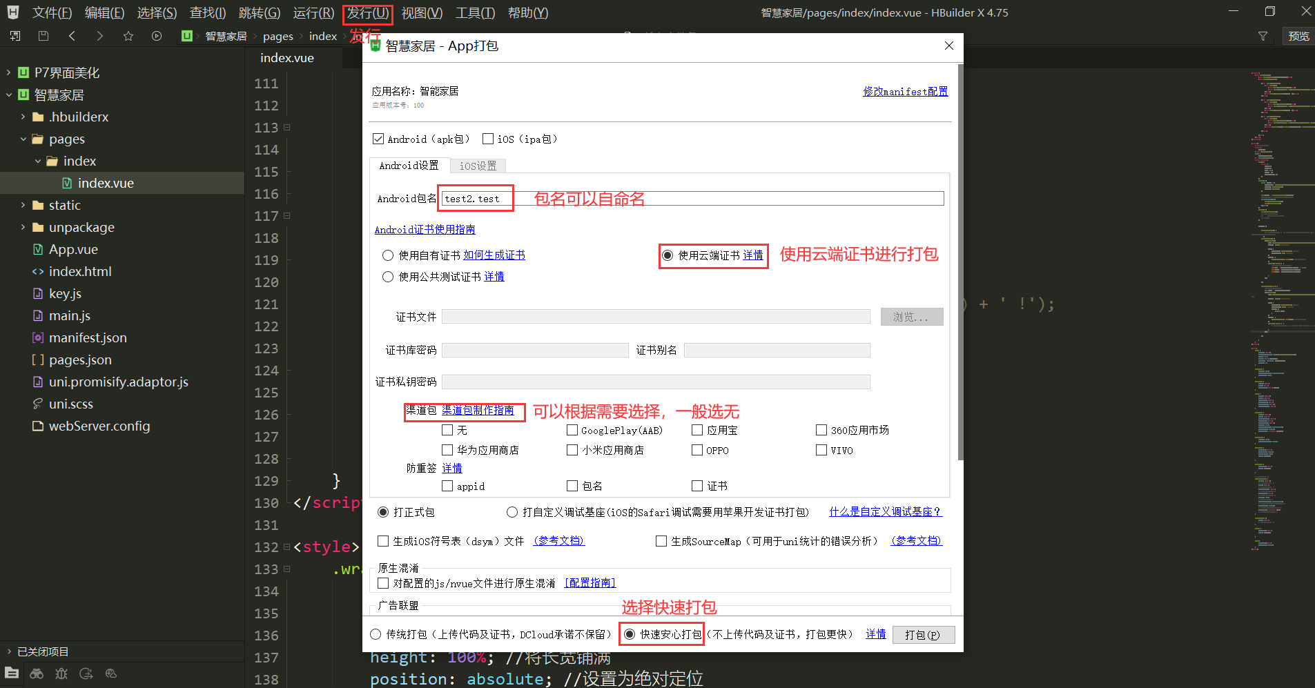
#endif6 HBuilder X
HBuilder X Project Download:
* Link: https://pan.baidu.com/s/1oIIr3oTnHG-we22AkLQu8w?pwd=6en9
* Extraction Code: `6en9`
Modification Steps:
1. Import into HBuilder X after downloading.
2. Modify the `index.vue` file:
* Modify the Token: Replace `author_key` and `user_id` in `const params = {
author_key: '', //user key
version: '2022-05-01',
user_id: '', //user ID
}` to generate the user Token.
* Modify the Product ID and Device Name: Replace `product_id` and `device_name` parameters in `url` with their actual values.
3. After modification, you can package the file into an app using HBuilder X's built-in publishing function.
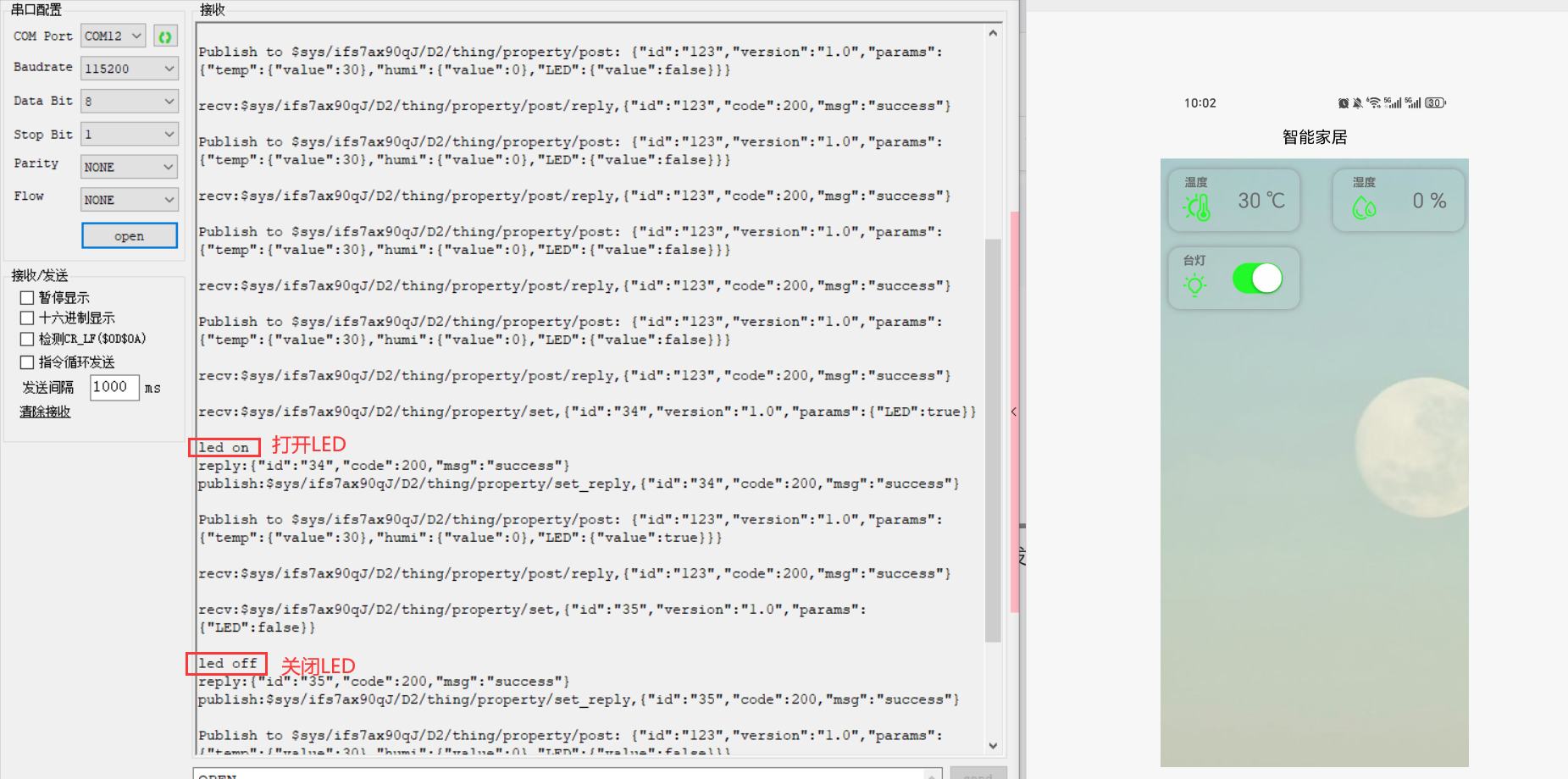
7. Function Verification
Opening the mobile app shows that the app successfully obtains data from the OneNET platform.
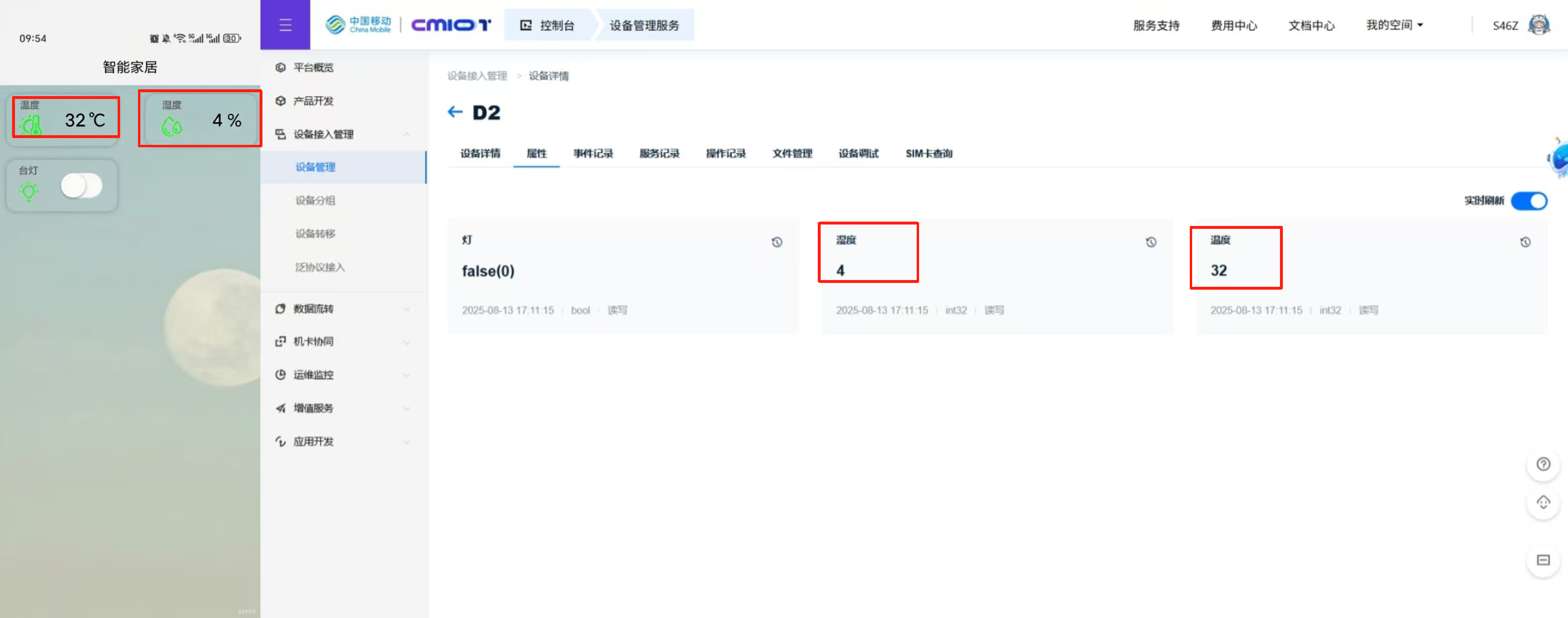
Sending commands through the mobile app, the serial port assistant prints the corresponding execution information, indicating successful command delivery.
8. Summary
This article details how a mobile app obtains sensor data collected by the W55MH32Q through the OneNET cloud platform and sends commands to control the corresponding device. Thank you for your patience in reading! If you have any questions during the reading process, or would like to learn more about this product and its applications, please feel free to leave a message via private message or in the comments section. We will reply to your message as soon as possible to provide you with more detailed answers and assistance!
———————————————— Copyright Notice: This article is an original article by CSDN blogger "Playing with Ethernet," and is licensed under CC 4.0 BY-SA. Please include the original source link and this statement when reprinting.
Original Link: https://blog.csdn.net/2301_81684513/article/details/150446682