



How to Stream OV2640 Camera Data with W5500 on STM32F4?
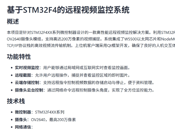
This project builds a remote camera system around an STM32F4 MCU, an OV2640 image sensor, and a WIZnet W5500 Ethernet controller.
How to Stream OV2640 Camera Data with W5500 on STM32F4?
Summary
This project builds a remote camera system around an STM32F4 MCU, an OV2640 image sensor, and a WIZnet W5500 Ethernet controller. The OV2640 supplies image data to the STM32F4 through its digital camera interface path, while the W5500 provides the wired TCP/IP transport to a Qt-based PC client. The important design problem is not simply Ethernet connectivity, but moving camera frames through DCMI, MCU memory, SPI, W5500 socket buffers, and TCP without making any single stage the throughput bottleneck.
What the Project Does
The project is a remote video-monitoring platform based on the STM32F4 family. The repository identifies the OV2640 as the camera, W5500 as the wired Ethernet interface, and a NodeMCU module as an additional Wi-Fi path. A Qt application on the PC side provides the user interface. The documented functions include remote image capture, control of image storage, camera pan/tilt control, and network delivery of camera data.
For the W5500 path, the relevant data flow is:
OV2640 → parallel camera data → STM32F4 DCMI/DMA → frame buffer or JPEG data → SPI → W5500 → TCP/IP → Ethernet → Qt client
STM32 DCMI is specifically designed to capture parallel camera signals such as pixel data, pixel clock, horizontal synchronization, and vertical synchronization. DMA can then transfer incoming camera data to memory without requiring the CPU to copy every pixel individually.
OV2640 is a 2-megapixel sensor with an integrated image-processing and compression engine. That compression capability is particularly important in an MCU-based network camera because transmitting compressed camera output requires substantially less bandwidth and memory traffic than moving uncompressed pixel frames.
The repository does not publish a measured frame rate, TCP throughput figure, SPI clock, camera resolution used during streaming, or JPEG quality setting. Performance claims for this particular implementation therefore cannot be stated as measured results. What can be analyzed reliably is the bandwidth budget of the OV2640-to-W5500 path.
Where WIZnet Fits
The WIZnet W5500 is the wired network endpoint between the STM32F4 and the Ethernet network.
Unlike an Ethernet controller that only provides a MAC/PHY, W5500 contains a hardwired TCP/IP engine together with a 10/100 Ethernet MAC and PHY. It supports TCP, UDP, IPv4, ICMP, ARP, IGMP, and PPPoE, provides eight independent hardware sockets, and contains 32 KB of internal TX/RX buffer memory. The STM32F4 controls it over SPI.
This matters in a camera application because the STM32F4 already has several time-sensitive jobs:
receiving the OV2640 pixel stream;
servicing DCMI/DMA events;
locating or managing frame boundaries;
controlling the camera over SCCB;
buffering image data;
processing remote commands;
and feeding image data into the network path.
With W5500, TCP retransmission, acknowledgements, connection state handling, ARP, Ethernet MAC processing, and similar network-stack work are executed by the Ethernet controller rather than by an lwIP task on the STM32 CPU.
The W5500 SPI interface supports clocks up to 80 MHz. That corresponds to a theoretical raw serial data ceiling of 10 MB/s before command phases, MCU-side software overhead, socket-buffer management, TCP behavior, and Ethernet overhead are considered. Consequently, the nominal 100BASE-TX interface should not be interpreted as meaning that an STM32 can continuously push 100 Mbit/s of camera payload through W5500. In this architecture, SPI and MCU memory movement can become limiting stages first.
OV2640 + W5500 Performance Budget
A useful way to understand the system is to calculate what would happen if the camera data were not compressed.
A 640 × 480 RGB565 image requires:
640 × 480 × 2 = 614,400 bytes per frame
The corresponding image payload alone would be approximately:
| Frame rate | Raw RGB565 payload |
|---|---|
| 10 fps | 49.2 Mbit/s |
| 15 fps | 73.7 Mbit/s |
| 30 fps | 147.5 Mbit/s |
These figures exclude SPI framing, TCP/IP headers, Ethernet framing, memory copies, and application framing.
This immediately exposes the problem. At 15 fps, raw VGA RGB565 already requires roughly 9.2 MB/s, approaching the W5500's theoretical 10 MB/s SPI ceiling at an 80 MHz SPI clock. At 30 fps, raw VGA requires about 18.4 MB/s, so it cannot pass through an 80 MHz SPI link even before protocol overhead is considered.
This is why the OV2640's integrated compression engine is technically significant. OMNIVISION specifically describes the sensor as incorporating an integrated compression engine intended to reduce camera-interface bandwidth. With JPEG-like compressed output, frame size becomes dependent on resolution, image complexity, and compression quality rather than simply width × height × bytes_per_pixel.
For example, if an application produces a 40 KB compressed frame, 10 fps represents only about 3.2 Mbit/s of image payload. An 80 KB frame at 10 fps would represent about 6.4 Mbit/s. These are illustrative calculations, not measurements from this repository, but they show why compressed camera output changes the feasibility of the STM32F4 + W5500 architecture.
The W5500's 32 KB internal memory should also not be confused with a camera framebuffer. It is network TX/RX memory shared among sockets. A camera frame can easily exceed a socket's available W5500 buffer, so the application must transmit the image incrementally rather than expecting the complete image to reside inside W5500.
W5500 versus lwIP
An lwIP design moves the networking boundary back into the STM32.
With lwIP, a typical path is:
OV2640 → DCMI/DMA → MCU memory → lwIP → Ethernet MAC/DMA → PHY
lwIP provides raw, sequential, and BSD-style socket APIs. Its raw API can operate without an RTOS and is specifically designed to reduce execution and memory overhead, but the TCP/IP protocol implementation still executes as software on the MCU.
The W5500 version is instead:
OV2640 → DCMI/DMA → MCU memory → W5500 socket API/registers → hardware TCP/IP → Ethernet
For an educational project, this distinction is useful. W5500 lets students concentrate on camera acquisition, DMA, buffering, SPI, socket operation, and application protocols without simultaneously having to study the configuration and memory behavior of a complete software TCP/IP stack.
The trade-off is control. lwIP gives the developer considerably more influence over the network stack, buffer architecture, interfaces, and protocol behavior. W5500 instead presents a fixed hardware socket architecture with eight sockets and configurable internal TX/RX memory.
Implementation Notes
The GitCode repository confirms that source code and schematics are supplied, but the implementation is distributed through a bundled source-and-schematic archive rather than as individually browsable source files in the indexed repository view. The visible project documentation verifies the STM32F4, OV2640, W5500, NodeMCU, TCP/IP, and Qt architecture, but it does not expose enough individual source lines to quote W5500 initialization or camera-transfer code safely. No reconstructed code is presented here.
At architecture level, the implementation should be understood as four cooperating stages.
Camera configuration: The STM32 configures OV2640 parameters through SCCB. The sensor then produces a parallel image stream together with pixel and frame synchronization signals.
Camera capture: STM32F4 DCMI receives that parallel stream. DMA is important because ST's DCMI architecture allows camera data to move from the peripheral toward memory without having the Cortex-M4 execute an instruction for every incoming byte.
Frame buffering: The MCU must determine where captured image data is stored and when enough data is available for transmission. The exact buffering requirement depends heavily on whether the project transports compressed OV2640 output or an uncompressed format. Exact SRAM capacity also depends on the particular STM32F4XX part, which the repository overview does not identify.
Ethernet transmission: The MCU sends image chunks over SPI into W5500 socket memory. W5500 then executes the TCP/IP and Ethernet portions of the transfer. Sequential SPI reads and writes are supported, making burst transfers preferable to issuing separate SPI transactions for small pieces of a camera frame.
For performance experiments, students should measure the complete pipeline rather than only the Ethernet link. Useful measurements include average JPEG frame size, camera FPS, DCMI capture time, SPI transfer time, TCP send time, dropped frames, and end-to-end latency at the Qt client.
Practical Tips / Pitfalls
Use compressed OV2640 output when network frame rate matters. Raw VGA RGB565 consumes 614,400 bytes per frame, making the MCU-to-W5500 SPI link a serious constraint at higher frame rates. OV2640's integrated compression capability substantially reduces this pressure.
Use DCMI with DMA rather than CPU-driven pixel copies. The camera stream and network path need to operate concurrently; wasting CPU cycles copying each incoming pixel reduces the time available for frame management and SPI transmission.
Transfer large sequential blocks to W5500. W5500 supports sequential SPI access. Repeatedly sending tiny image fragments increases CS transitions, SPI command overhead, and CPU intervention.
Treat the W5500 socket buffer as transport buffering, not image storage. Its 32 KB total TX/RX memory is far smaller than many uncompressed frames, so image transmission needs chunking and producer/consumer flow control.
Measure SPI throughput separately from Ethernet throughput. A negotiated 100 Mbit/s Ethernet link does not prove that the MCU can supply data that quickly. SPI frequency, firmware implementation, memory copies, and socket waiting time can dominate the result.
Avoid blocking on TCP while a new camera frame is arriving. A double-buffer or producer/consumer design allows DCMI/DMA to acquire one region while the network task transmits another. ST documents double-buffer approaches for continuous camera acquisition.
Instrument frame drops explicitly. Add sequence numbers and timestamps to transmitted frames. A visually smooth Qt display can hide dropped images, while counters make camera capture and network bottlenecks measurable.
FAQ
Q: Why use W5500 with an OV2640 camera instead of implementing Ethernet with lwIP?
A: W5500 moves TCP/IP processing into dedicated hardware, leaving the STM32F4 primarily responsible for camera capture, buffer management, application control, and moving payload data over SPI. With lwIP, TCP/IP executes on the MCU and competes for CPU and memory resources with the DCMI camera path. lwIP provides more stack-level flexibility, while W5500 provides a simpler hardware-socket model for an educational camera system.
Q: How does W5500 connect to the STM32F4 in this camera architecture?
A: W5500 uses SPI, with the MCU acting as master. The normal interface consists of SCLK, MOSI, MISO, and SCSn, with reset and interrupt signals available as required. W5500 supports SPI Mode 0 and Mode 3 and clocks up to 80 MHz. Camera data captured through DCMI/DMA is ultimately written by the STM32 into W5500 socket TX memory over this interface.
Q: What role does W5500 play specifically in the OV2640 project?
A: It provides the wired TCP/IP path between the STM32F4 camera node and the remote Qt client. OV2640 generates the image data, STM32F4 captures and manages the frame, and W5500 turns the resulting payload into TCP/Ethernet communication. The repository also contains a NodeMCU Wi-Fi path, so W5500 represents the project's wired-network option rather than the camera interface itself.
Q: Can beginners use this project to learn network cameras?
A: It is better suited to students who already understand basic STM32 development. Useful prerequisites are SPI, DMA, interrupts, TCP sockets, MCU memory management, and basic digital camera timing. The design is educational because it separates the problem into understandable blocks: OV2640 acquisition, DCMI/DMA buffering, W5500 transport, and PC-side image handling.
Q: Is W5500 faster than lwIP for OV2640 streaming?
A: There is no repository benchmark that supports a direct FPS comparison. W5500 removes software TCP/IP processing from the STM32, but its camera throughput can be constrained by the SPI host interface. An lwIP implementation can use an MCU's native Ethernet MAC and DMA and therefore avoids an external SPI hop, but it consumes MCU memory and processing for the network stack. Which implementation achieves higher frame rate depends on the STM32 variant, SPI configuration, Ethernet MAC availability, JPEG frame size, buffering strategy, and software design.
Source
Original project: STM32F4 Remote Video Monitoring System, open-source-toolkit/868e9 on GitCode. The repository documents STM32F4, OV2640, W5500 Ethernet, NodeMCU Wi-Fi, TCP/IP, and a Qt PC application, and provides a bundled source-code and schematic package.
WIZnet reference: W5500 Datasheet Version 1.1.0, covering the hardwired TCP/IP engine, eight sockets, 32 KB TX/RX memory, 10/100 Ethernet PHY, and SPI operation up to 80 MHz.
Camera reference: OMNIVISION OV2640 product material identifying the device as a 2-megapixel sensor with integrated image processing and compression.
MCU camera-interface reference: STMicroelectronics AN5020, describing STM32 DCMI, DMA-based camera acquisition, buffering, and camera data paths.
Software-stack reference: Official lwIP raw API documentation.
License: The repository contains a LICENSE file, but the license text is not exposed in the indexed project view used for this analysis, so the exact license could not be verified.
Tags
#W5500 #OV2640 #STM32F4 #EthernetCamera #TCPIP #DCMI #DMA #SPI #lwIP #EmbeddedVision #Education
STM32F4에서 W5500으로 OV2640 카메라 데이터를 스트리밍하는 방법은?
Summary
이 프로젝트는 STM32F4 MCU, OV2640 이미지 센서, WIZnet W5500 Ethernet 컨트롤러를 기반으로 원격 카메라 시스템을 구현합니다. OV2640은 STM32F4의 디지털 카메라 인터페이스를 통해 영상 데이터를 전달하고, W5500은 유선 TCP/IP 통신을 통해 Qt 기반 PC 클라이언트로 이미지를 전송합니다. 핵심 설계 과제는 단순한 Ethernet 연결이 아니라 DCMI → MCU 메모리 → SPI → W5500 소켓 버퍼 → TCP로 이어지는 전체 경로에서 병목 없이 카메라 프레임을 전달하는 것입니다.
What the Project Does
이 프로젝트는 STM32F4 계열 MCU를 기반으로 한 원격 영상 모니터링 시스템입니다. 저장소에서는 OV2640을 카메라로, W5500을 유선 Ethernet 인터페이스로, NodeMCU를 추가적인 Wi-Fi 통신 경로로 사용합니다. PC 측에서는 Qt 애플리케이션이 사용자 인터페이스를 제공합니다.
프로젝트에서 확인되는 주요 기능은 다음과 같습니다.
- 원격 이미지 캡처
- 이미지 저장 제어
- 카메라 팬/틸트 제어
- 네트워크를 통한 영상 데이터 전송
W5500을 사용하는 유선 경로의 데이터 흐름은 다음과 같이 볼 수 있습니다.
OV2640 → 병렬 카메라 데이터 → STM32F4 DCMI/DMA → Frame Buffer 또는 JPEG 데이터 → SPI → W5500 → TCP/IP → Ethernet → Qt Client
STM32의 DCMI는 카메라에서 출력되는 병렬 Pixel Data, Pixel Clock, Horizontal Sync, Vertical Sync 신호를 수신하도록 설계되어 있습니다. DMA를 함께 사용하면 Cortex-M4 CPU가 각 Pixel Byte를 직접 복사하지 않고도 카메라 데이터를 메모리로 이동할 수 있습니다.
OV2640은 2 Megapixel 이미지 센서이며 내부에 이미지 처리 및 압축 기능을 포함합니다. MCU 기반 네트워크 카메라에서는 이 압축 기능이 중요합니다. 압축되지 않은 Pixel 데이터를 그대로 Ethernet으로 전달하는 것보다 MCU 메모리와 네트워크 대역폭 요구량을 크게 줄일 수 있기 때문입니다.
다만 저장소에는 실제 측정된 Frame Rate, TCP Throughput, SPI Clock, Streaming Resolution, JPEG Quality 설정이 공개되어 있지 않습니다. 따라서 이 프로젝트의 실제 성능을 특정 FPS나 Mbps 수치로 단정할 수는 없습니다.
대신 OV2640에서 W5500까지 이어지는 데이터 경로의 이론적 Bandwidth Budget은 분석할 수 있습니다.
Where WIZnet Fits
이 프로젝트에서 WIZnet W5500은 STM32F4와 Ethernet 네트워크 사이의 유선 TCP/IP Endpoint 역할을 합니다.
W5500은 단순한 Ethernet MAC/PHY 칩이 아닙니다. 내부에 Hardwired TCP/IP Engine과 10/100 Ethernet MAC/PHY를 포함하며, TCP, UDP, IPv4, ICMP, ARP, IGMP 등을 하드웨어에서 처리합니다.
또한 다음과 같은 네트워크 자원을 제공합니다.
- 8개의 Hardware Socket
- 총 32 KB의 TX/RX Buffer Memory
- SPI Host Interface
STM32F4는 SPI를 통해 W5500을 제어합니다.
이 구조가 카메라 프로젝트에서 중요한 이유는 STM32F4가 이미 여러 실시간 작업을 수행해야 하기 때문입니다.
- OV2640 Image Stream 수신
- DCMI/DMA Event 처리
- Frame Boundary 관리
- SCCB를 통한 Camera Register 설정
- Image Buffer 관리
- 원격 명령 처리
- W5500으로 영상 데이터 전달
W5500을 사용하면 TCP Retransmission, ACK 처리, TCP Connection State, ARP, Ethernet MAC 처리와 같은 네트워크 스택 기능을 STM32에서 직접 수행하지 않아도 됩니다.
즉, MCU는 카메라 데이터 처리와 Application Logic에 더 집중할 수 있습니다.
W5500의 SPI Interface는 최대 80 MHz까지 지원합니다.
80 MHz를 단순히 Byte 단위로 환산하면 이론적으로 약:
80 Mbit/s ÷ 8 = 10 MB/s
입니다.
하지만 실제 전송에서는 SPI Command Phase, MCU Software Overhead, Socket Buffer Management, TCP 동작, Ethernet Header 등이 추가됩니다.
따라서 W5500이 100BASE-TX를 지원한다고 해서 STM32가 항상 100 Mbit/s의 Camera Payload를 전달할 수 있다는 의미는 아닙니다.
이 구조에서는 Ethernet PHY보다 먼저 SPI와 MCU Memory Transfer가 병목이 될 수 있습니다.
OV2640 + W5500 Performance Budget
카메라 데이터를 압축하지 않는다고 가정하면 병목이 더 명확하게 보입니다.
640 × 480 해상도의 RGB565 영상 한 Frame은 다음 크기를 갖습니다.
640 × 480 × 2 = 614,400 bytes/frame
Frame Rate별 Raw Image Payload는 대략 다음과 같습니다.
| Frame Rate | Raw RGB565 Payload |
|---|---|
| 10 fps | 약 49.2 Mbit/s |
| 15 fps | 약 73.7 Mbit/s |
| 30 fps | 약 147.5 Mbit/s |
이 수치는 SPI Header, TCP/IP Header, Ethernet Frame, Memory Copy 등의 Overhead를 포함하지 않습니다.
여기서 중요한 문제가 나타납니다.
VGA RGB565 기준 15 fps는 약:
614,400 × 15 = 9.216 MB/s
입니다.
이는 W5500 SPI를 80 MHz로 구동했을 때의 이론적 최대치인 약 10 MB/s에 이미 근접합니다.
30 fps에서는 약:
18.4 MB/s
가 필요하므로 W5500의 80 MHz SPI Link만으로도 처리할 수 없습니다.
따라서 이 프로젝트에서 OV2640의 압축 기능이 매우 중요합니다.
예를 들어 압축된 한 Frame이 40 KB라고 가정하면:
40 KB × 10 fps ≈ 400 KB/s
즉 약:
3.2 Mbit/s
정도의 Image Payload가 됩니다.
한 Frame이 80 KB일 경우에도 10 fps 기준 약:
6.4 Mbit/s
수준입니다.
이 값들은 저장소에서 측정된 실제 결과가 아니라 구조를 설명하기 위한 계산 예시입니다.
하지만 왜 MCU + W5500 Camera System에서 JPEG와 같은 압축 출력이 중요한지는 분명하게 보여줍니다.
또 하나 주의할 점은 W5500 내부의 32 KB Buffer가 Camera Frame Buffer가 아니라는 것입니다.
이 메모리는 W5500의 Socket TX/RX를 위해 사용되는 Network Buffer입니다.
카메라 Frame 하나가 W5500 Socket Buffer보다 클 수 있기 때문에 MCU는 전체 이미지를 W5500 안에 저장하려고 해서는 안 됩니다.
대신 다음과 같은 방식이 필요합니다.
Camera Frame → MCU Buffer → 여러 Chunk로 분할 → W5500 TX Buffer → TCP 전송
W5500 versus lwIP
lwIP를 사용하면 Network Stack의 위치가 STM32 내부로 이동합니다.
일반적인 lwIP 구조는 다음과 같습니다.
OV2640 → DCMI/DMA → MCU Memory → lwIP → Ethernet MAC/DMA → PHY
lwIP는 Raw API, Sequential API, BSD-style Socket API 등을 제공하는 Software TCP/IP Stack입니다.
Raw API를 사용하면 RTOS 없이도 동작할 수 있지만 TCP/IP Protocol Processing 자체는 여전히 MCU에서 수행됩니다.
반면 W5500 구조는 다음과 같습니다.
OV2640 → DCMI/DMA → MCU Memory → W5500 Socket Interface → Hardware TCP/IP → Ethernet
즉 TCP/IP Processing을 외부 W5500으로 이동시킵니다.
교육 관점에서 이 차이는 중요합니다.
W5500을 사용하면 학생들이 다음 부분에 집중할 수 있습니다.
- Camera Capture
- DMA
- Buffering
- SPI
- Socket Operation
- Application Protocol
동시에 복잡한 Software TCP/IP Stack의 설정과 Memory Management까지 처음부터 다룰 필요는 없습니다.
반대로 lwIP는 Network Stack 내부 동작을 더 세밀하게 제어할 수 있다는 장점이 있습니다.
Stack Configuration, Buffer Structure, Interface, Protocol Behavior 등을 소프트웨어에서 조절할 수 있기 때문입니다.
따라서 두 방식은 단순히 어느 쪽이 더 빠른가의 문제가 아니라 설계 목표가 다릅니다.
W5500: TCP/IP 처리 단순화와 MCU 부하 분리
lwIP: Software Stack의 유연성과 세밀한 제어
Implementation Notes
GitCode 저장소에서는 Source Code와 Schematic이 제공되는 것을 확인할 수 있지만, 구현 파일들이 웹 페이지에서 개별 Source File 형태로 완전히 노출되기보다는 압축된 Source/Schematic Package 중심으로 배포됩니다.
공개된 프로젝트 정보에서는 STM32F4, OV2640, W5500, NodeMCU, TCP/IP, Qt 구조를 확인할 수 있지만, W5500 초기화나 Camera Data 전송 코드의 개별 Source Line을 충분히 검증할 수 없습니다.
따라서 여기서는 실제 저장소에 없는 코드를 임의로 생성하지 않고 Architecture Level에서 구현 구조를 설명합니다.
Camera Configuration
STM32는 SCCB를 통해 OV2640 Register를 설정합니다.
설정이 끝나면 OV2640은 Parallel Image Data와 함께 Pixel Clock 및 Frame Synchronization Signal을 출력합니다.
Camera Capture
STM32F4의 DCMI가 OV2640의 병렬 데이터를 수신합니다.
이때 DMA를 함께 사용하는 것이 중요합니다.
DMA를 사용하면 Camera Peripheral에서 Memory로 Image Data를 이동하는 동안 Cortex-M4가 각 Byte를 직접 처리할 필요가 없습니다.
결과적으로 CPU는 다음 작업에 더 많은 시간을 사용할 수 있습니다.
- Frame Management
- Network Transmission
- Remote Control
- Application Logic
Frame Buffering
MCU는 카메라에서 수신된 데이터가 어디에 저장되는지 관리해야 합니다.
필요한 Buffer 크기는 Image Format에 따라 크게 달라집니다.
Raw RGB565에서는 VGA Frame 하나가 약 600 KB이므로 MCU Internal SRAM만으로 전체 Frame을 처리하기 어려울 수 있습니다.
반면 OV2640의 Compressed Output을 사용하면 Frame Size를 크게 줄일 수 있습니다.
정확한 Memory Capacity는 사용된 STM32F4 세부 모델에 따라 달라지지만, 저장소의 공개 설명만으로 정확한 Part Number와 SRAM 구조까지 확인하기는 어렵습니다.
Ethernet Transmission
STM32F4는 Image Data를 SPI를 통해 W5500 Socket TX Memory로 전달합니다.
W5500은 이후 TCP/IP와 Ethernet 처리를 수행합니다.
Camera Streaming에서는 작은 데이터 조각을 지나치게 자주 전송하는 것보다 가능한 범위에서 큰 Sequential Block을 사용하는 것이 효율적입니다.
너무 작은 Chunk를 반복하면 다음 Overhead가 증가할 수 있습니다.
- SCSn Toggle
- SPI Address/Control Phase
- Function Call
- Interrupt
- Socket Status Check
성능 평가 시에는 단순히 Ethernet Link Speed만 확인해서는 부족합니다.
다음 항목을 각각 측정하는 것이 좋습니다.
- Average JPEG Frame Size
- Camera FPS
- DCMI Capture Time
- SPI Transfer Time
- TCP Send Time
- Dropped Frame Count
- End-to-End Display Latency
Practical Tips / Pitfalls
- 높은 Frame Rate가 필요하다면 OV2640의 압축 출력을 사용하는 것이 중요합니다. VGA RGB565 한 Frame은 약 614 KB이므로 압축되지 않은 영상은 W5500 SPI 대역폭을 빠르게 소모합니다.
- DCMI와 DMA를 함께 사용하는 것이 좋습니다. Camera Pixel을 CPU가 직접 복사하면 Network 처리와 Frame 관리에 사용할 CPU 시간이 감소합니다.
- W5500으로 가능한 한 큰 Sequential Block을 전송하는 것이 유리합니다. 너무 작은 Image Fragment를 반복적으로 보내면 SPI Command와 CS 제어 Overhead가 증가합니다.
- W5500 Socket Buffer를 Camera Frame Buffer로 사용해서는 안 됩니다. W5500의 32 KB 메모리는 Network TX/RX 용도이므로 큰 Image Frame은 여러 Chunk로 나누어 전송해야 합니다.
- Ethernet Throughput과 SPI Throughput을 별도로 측정해야 합니다. Ethernet Link가 100 Mbit/s로 연결되었다고 해서 MCU가 같은 속도로 Camera Data를 공급할 수 있다는 의미는 아닙니다.
- TCP 송신 때문에 Camera Capture가 Block되지 않도록 설계해야 합니다. Double Buffer 또는 Producer/Consumer 구조를 사용하면 한 Buffer를 DCMI/DMA가 채우는 동안 다른 Buffer를 Network로 전송할 수 있습니다.
- Frame Drop을 정량적으로 측정하는 것이 좋습니다. Frame Sequence Number와 Timestamp를 넣으면 Qt 화면만 보는 것보다 실제 Camera/Network Bottleneck을 정확하게 확인할 수 있습니다.
FAQ
Q: OV2640 카메라 프로젝트에서 lwIP 대신 W5500을 사용하는 이유는 무엇인가요?
A: W5500은 TCP/IP 처리를 전용 하드웨어에서 수행하므로 STM32F4는 Camera Capture, Buffer Management, Application Control, SPI Payload Transfer에 집중할 수 있습니다. lwIP를 사용하면 TCP/IP Stack 자체가 STM32에서 실행되기 때문에 DCMI Camera 처리와 CPU 및 Memory Resource를 함께 사용하게 됩니다. 반대로 lwIP는 Network Stack을 더 유연하게 제어할 수 있다는 장점이 있습니다.
Q: W5500은 STM32F4와 어떻게 연결되나요?
A: W5500은 SPI를 통해 STM32F4와 연결됩니다. 기본 신호는 SCLK, MOSI, MISO, SCSn이며 필요에 따라 INTn과 RSTn도 사용할 수 있습니다. W5500은 SPI Mode 0과 Mode 3을 지원하며 최대 80 MHz SPI Clock을 지원합니다. OV2640에서 DCMI/DMA로 수신된 영상 데이터는 최종적으로 SPI를 통해 W5500의 Socket TX Buffer로 전달됩니다.
Q: 이 OV2640 프로젝트에서 W5500은 정확히 어떤 역할을 하나요?
A: W5500은 STM32F4 Camera Node와 원격 Qt Client 사이의 유선 TCP/IP 통신을 담당합니다. OV2640이 이미지를 생성하고, STM32F4가 DCMI/DMA로 이미지를 수신하고 관리하며, W5500은 그 데이터를 TCP/Ethernet으로 전송합니다. 저장소에는 NodeMCU 기반 Wi-Fi 경로도 포함되어 있으므로 W5500은 이 시스템의 유선 네트워크 경로라고 볼 수 있습니다.
Q: 초보자도 이 프로젝트로 Network Camera를 학습할 수 있나요?
A: STM32를 처음 사용하는 단계보다는 기본 MCU 개발 경험이 있는 학습자에게 적합합니다. SPI, DMA, Interrupt, TCP Socket, MCU Memory Management, 기본적인 Camera Timing에 대한 이해가 있으면 구조를 따라가기 쉽습니다. OV2640 Capture, DCMI/DMA, W5500 Transport, Qt Client가 명확하게 분리되어 있어 교육용으로 분석하기 좋은 구조입니다.
Q: OV2640 Streaming에서는 W5500이 lwIP보다 더 빠른가요?
A: 저장소에는 두 방식을 직접 비교한 FPS 또는 Throughput Benchmark가 없으므로 W5500이 항상 더 빠르다고 말할 수 없습니다. W5500은 TCP/IP 처리를 STM32에서 분리하지만 SPI Interface가 추가적인 Bandwidth 제한이 될 수 있습니다. 반면 lwIP가 STM32의 Native Ethernet MAC/DMA와 함께 사용된다면 SPI 단계가 없기 때문에 높은 Throughput을 낼 가능성이 있지만 CPU와 Memory에서 Software TCP/IP Stack을 실행해야 합니다. 실제 Frame Rate는 STM32 모델, SPI Clock, JPEG Frame Size, Buffer 구조, DMA 설정, Network Software 설계에 따라 달라집니다.
Source
Original Project: GitCode open-source-toolkit/868e9, STM32F4 기반 Remote Video Monitoring System
프로젝트에서는 STM32F4, OV2640, W5500 Ethernet, NodeMCU Wi-Fi, TCP/IP, Qt PC Application으로 구성된 Remote Camera System을 설명하고 있으며 Source Code와 Schematic Package를 제공합니다.
WIZnet Technical Reference: W5500 Datasheet Version 1.1.0
W5500의 Hardwired TCP/IP Engine, 8개의 Socket, 32 KB TX/RX Buffer, 10/100 Ethernet PHY, 최대 80 MHz SPI Interface를 확인할 수 있습니다.
Camera Reference: OMNIVISION OV2640 Technical Material
OV2640은 2 Megapixel Sensor이며 Integrated Image Processing 및 Compression Engine을 제공합니다.
MCU Camera Interface Reference: STMicroelectronics AN5020
STM32 DCMI, DMA 기반 Camera Acquisition, Buffering 및 Continuous Capture 구조를 설명합니다.
Software Stack Reference: lwIP Official Documentation
Software 기반 TCP/IP Stack과 Raw API 구조를 설명합니다.
License: 저장소에 LICENSE 파일은 존재하지만, 이번에 확인 가능한 Repository View에서는 License 본문을 충분히 검증하지 못했으므로 정확한 License 종류는 특정하지 않습니다.
Tags
#W5500 #OV2640 #STM32F4 #EthernetCamera #TCPIP #DCMI #DMA #SPI #lwIP #EmbeddedVision #Education