



How to Design Reliable Ethernet Wiring with WIZnet W5500 on MCU Boards?
This education-focused project explains how to design a stable Ethernet interface around the WIZnet W5500 on an MCU board.
How to Design Reliable Ethernet Wiring with WIZnet W5500 on MCU Boards?
Summary
This education-focused project explains how to design a stable Ethernet interface around the WIZnet W5500 on an MCU board. The source concentrates on cable selection, connector choice, wiring order, trace layout, grounding, shielding, and electromagnetic compatibility rather than application firmware. W5500 provides the Ethernet PHY, MAC, hardwired TCP/IP stack, sockets, and packet buffers, while the MCU communicates through SPI and uses W5500 registers to verify chip identity, PHY link state, negotiated speed, socket state, and communication health.
What the Project Does
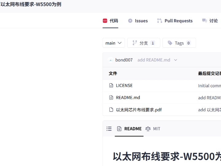
The GitCode project is a W5500-based Ethernet wiring guide. Its repository contains a README, an MIT license marker, and a PDF titled 以太网芯片布线要求.pdf. The visible project description says the material covers Ethernet fundamentals, cable selection, wiring sequence, connector types, cable-length considerations, shielding, grounding, layout rules, and techniques for improving electromagnetic compatibility.
The system-level signal path is:
MCU application → SPI interface → W5500 registers and socket buffers → W5500 MAC/PHY → MDI differential pairs → transformer or magnetics RJ45 → Ethernet cable → switch or peer device
The project is useful in education because it connects three engineering domains that are often taught separately: digital SPI communication, register-based Ethernet diagnosis, and analog high-speed PCB layout. A board can pass basic SPI tests while still failing Ethernet operation because of poor differential routing, magnetics selection, power integrity, grounding, or connector placement.
The repository exposes the PDF filename and project summary, but the GitCode preview did not make the complete PDF body inspectable during verification. Detailed project-specific dimensions or routing constraints are therefore not attributed to that PDF unless they are independently supported by WIZnet’s official hardware references.
Where WIZnet Fits
The exact WIZnet product is W5500. It sits between the MCU and the Ethernet magnetics. On the MCU side, it uses SCSn, SCLK, MOSI, and MISO, with RSTn and optionally INTn. On the network side, it exposes the TXP, TXN, RXP, and RXN MDI signals that connect to an Ethernet transformer or an RJ45 connector with integrated magnetics.
W5500 integrates a 10/100 Ethernet MAC and PHY, a hardwired TCP/IP stack, eight independent sockets, and 32 KB of internal Tx/Rx memory. Its SPI interface supports modes 0 and 3 and operation up to 80 MHz.
The physical layout directly affects whether these functions operate reliably. WIZnet’s design guidance recommends keeping the W5500-to-RJ45 path short, routing each Tx and Rx pair with equal intra-pair length, preventing unrelated digital signals from crossing the MDI area, and designing the differential path for 100-ohm impedance with the PCB manufacturer’s stack-up data.
Implementation Notes
The project is a hardware-routing resource rather than an inspectable firmware repository, so there is no verified project-specific code to quote. A useful educational implementation should combine the physical design with a register-based board bring-up sequence.
MCU-side interface
Connect the MCU SPI controller to SCLK, MOSI, MISO, and SCSn. Use host-controlled chip select and variable-length SPI transfers when the SPI bus must be shared with other peripherals. W5500 latches SPI data on the rising clock edge and outputs data on the falling edge in both supported SPI modes.
Connect RSTn to an MCU GPIO rather than relying only on power-on reset. Connecting INTn is recommended for experiments involving socket receive, disconnect, timeout, and send-complete events, although a basic laboratory exercise can start with polling.
Ethernet-side interface
Follow the exact WIZnet reference circuit for the selected transformer or integrated-magnetics RJ45. Component values depend on the magnetics topology, so the termination, center-tap, chassis-ground, and isolation-capacitor arrangement should not be copied from an unrelated Ethernet device. WIZnet publishes separate reference designs for external transformers and RJ45 connectors with integrated magnetics.
Place the W5500, magnetics, and RJ45 so the MDI path remains short and direct. Keep each differential pair length-matched, maintain a continuous reference structure, and avoid high-frequency oscillators, switching power nodes, and unrelated digital traces near the Tx/Rx paths. WIZnet also recommends local decoupling for each power input and careful treatment of analog and digital supply regions.
Register-based validation
The first firmware test should read VERSIONR at address 0x0039. The W5500 datasheet defines its value as 0x04. A stable read confirms basic power, reset, chip select, SPI mode, and digital communication, but it does not prove that the Ethernet analog path is correct.
Next, read PHYCFGR at 0x002E. Its status bits report link, speed, and duplex, while its control bits can select or reset the PHY operating mode. If VERSIONR is correct but the link bit remains clear with a known-good cable and switch, investigate the magnetics circuit, MDI routing, crystal, analog supply, reference resistor, connector, and soldering before debugging sockets.
After link-up, inspect socket-related registers such as Sn_SR, Sn_IR, Sn_TX_FSR, and Sn_RX_RSR. These distinguish physical-link problems from socket-state, transmit-buffer, receive-buffer, or application-protocol problems.
Practical Tips / Pitfalls
- Read
VERSIONRrepeatedly at a low SPI clock before increasing bus speed. - Keep the W5500, magnetics, and RJ45 physically close and route Tx/Rx as controlled differential pairs.
- Use the exact transformer or integrated-RJ45 reference circuit associated with the chosen component.
- Keep switching regulators, crystals from unrelated circuits, and fast digital buses away from the MDI traces.
- Log
PHYCFGR,Sn_SR,Sn_IR,Sn_TX_FSR, andSn_RX_RSRduring cable and socket tests. - Test with multiple cables and switches so one marginal cable does not hide a board-layout problem.
- Include cable removal, link renegotiation, reset recovery, continuous traffic, and ESD-oriented bench testing in the lab plan.
FAQ
Q: Why use WIZnet W5500 for an Ethernet wiring education project?
A: W5500 exposes both sides of embedded Ethernet clearly. Students can inspect SPI transactions and network registers on the digital side while studying differential routing, magnetics, grounding, shielding, and connector placement on the physical side. Its integrated MAC, PHY, TCP/IP engine, eight sockets, and packet memory keep the exercise focused without requiring a full software TCP/IP stack.
Q: How does W5500 connect to an MCU board?
A: The MCU uses SPI signals SCLK, MOSI, MISO, and SCSn, plus RSTn and optionally INTn. The Ethernet side uses the W5500 MDI pairs through approved magnetics to RJ45. W5500 supports SPI modes 0 and 3.
Q: What role do W5500 registers play in this project?
A: Registers make the hardware bring-up measurable. VERSIONR verifies digital access, PHYCFGR reports link, speed, and duplex, and socket registers report connection state, interrupt causes, available transmit space, and received data. They help separate SPI faults, physical-layer faults, and network-protocol faults.
Q: Can beginners follow this project?
A: Yes. A suitable sequence is schematic review, SPI wiring, VERSIONR read, PHYCFGR link test, static IP configuration, UDP echo, and then TCP testing. Basic familiarity with SPI, PCB grounding, differential pairs, and hexadecimal registers is helpful.
Q: How does a W5500 design compare with a USR Ethernet module?
A: A representative USR product such as the USR-TCP232-T2 is a module-level serial-to-Ethernet converter. It accepts 3.3 V TTL serial data, provides an RJ45 interface, and offers configuration through AT commands, a built-in webpage, software tools, or a configuration protocol. It is designed for transparent serial transport and functions such as TCP client/server, UDP, and Modbus gateway operation.
W5500 is a chip-level Ethernet controller. The MCU directly owns the socket configuration, registers, packet buffers, protocol logic, diagnostics, and recovery behavior, but the PCB designer must implement the power, clock, magnetics, MDI routing, and EMC details. The USR module reduces physical-layer and network-integration work but gives the host a serial-converter interface rather than direct W5500 register and socket control. The USR approach is easier for converting an existing UART product; W5500 is better for teaching or implementing tightly integrated MCU networking.
Source
Original project: GitCode, “以太网布线要求-W5500为例: 基于 W5500 的以太网布线指南项目.” The visible repository identifies the W5500 wiring PDF, README content, and MIT license marker.
Related description: CSDN, “以太网布线要求-W5500为例.” The article is published under CC 4.0 BY-SA and summarizes the project’s coverage of Ethernet wiring, cable and connector selection, shielding, grounding, EMC, and layout guidance.
WIZnet references: Official W5500 datasheet, external-transformer reference schematic, reference-schematic index, and Ethernet hardware design guide.
Comparison reference: PUSR/USR-TCP232-T2 official product documentation for serial-to-Ethernet operation, configuration methods, supported modes, and electrical interfaces.
Tags
#W5500 #WIZnet #EthernetLayout #PCBDesign #Registers #PHYCFGR #SPI #Education #EMC #Magnetics #RJ45 #USRTCP232
MCU 보드에서 WIZnet W5500으로 안정적인 이더넷 배선을 설계하는 방법은?
요약
이 교육용 프로젝트는 MCU 보드에서 WIZnet W5500을 중심으로 안정적인 이더넷 인터페이스를 설계하는 방법을 설명합니다. 원본 자료는 애플리케이션 펌웨어보다 케이블 선택, 커넥터 구성, 배선 순서, PCB 패턴 배치, 접지, 차폐, 전자파 적합성에 중점을 둡니다. W5500은 이더넷 PHY, MAC, 하드웨어 TCP/IP 스택, 소켓, 패킷 버퍼를 제공하고, MCU는 SPI를 통해 W5500을 제어합니다. 또한 W5500 레지스터를 사용해 칩 식별, PHY 링크 상태, 협상 속도, 소켓 상태, 통신 상태를 확인할 수 있습니다.
프로젝트가 하는 일
GitCode 프로젝트는 W5500 기반 이더넷 배선 가이드입니다. 저장소에는 README, MIT 라이선스 표시, 以太网芯片布线要求.pdf라는 PDF가 포함되어 있습니다. 공개된 프로젝트 설명에 따르면 다음 내용을 다룹니다.
이더넷 기본 원리
케이블 선택
배선 순서
커넥터 종류
케이블 길이 고려 사항
차폐 및 접지
PCB 레이아웃 규칙
전자파 적합성 개선 방법
시스템 수준의 신호 경로는 다음과 같습니다.
MCU 애플리케이션 → SPI 인터페이스 → W5500 레지스터 및 소켓 버퍼 → W5500 MAC/PHY → MDI 차동 신호쌍 → 트랜스포머 또는 마그네틱 내장 RJ45 → 이더넷 케이블 → 스위치 또는 상대 장치
이 프로젝트는 교육 측면에서 디지털 SPI 통신, 레지스터 기반 이더넷 진단, 고속 아날로그 PCB 설계를 하나의 실습으로 연결한다는 점에서 유용합니다. 보드가 기본적인 SPI 테스트를 통과하더라도 차동 배선, 마그네틱 부품 선택, 전원 무결성, 접지, 커넥터 배치가 부적절하면 실제 이더넷 링크는 동작하지 않을 수 있습니다.
저장소에서 PDF 파일명과 프로젝트 개요는 확인할 수 있었지만, GitCode 미리보기에서는 PDF 전체 내용을 검토할 수 없었습니다. 따라서 세부 배선 치수나 프로젝트 고유의 규칙은 WIZnet 공식 하드웨어 자료로 확인되는 경우에만 적용해야 합니다.
WIZnet이 들어가는 위치
이 프로젝트에서 사용하는 정확한 WIZnet 제품은 W5500입니다. W5500은 MCU와 이더넷 마그네틱 회로 사이에 위치합니다.
MCU 측에서는 다음 신호를 사용합니다.
SCSn
SCLK
MOSI
MISO
RSTn
선택적인 INTn
네트워크 측에서는 TXP, TXN, RXP, RXN MDI 신호를 제공합니다. 이 신호들은 이더넷 트랜스포머 또는 마그네틱이 내장된 RJ45 커넥터에 연결됩니다.
W5500은 다음 기능을 통합합니다.
10/100 이더넷 MAC 및 PHY
하드웨어 TCP/IP 스택
8개의 독립 소켓
32KB 내부 송수신 메모리
SPI 모드 0 및 3
최대 80MHz SPI 동작
실제 보드 레이아웃은 이러한 기능의 신뢰성에 직접 영향을 줍니다. WIZnet 설계 가이드에서는 W5500과 RJ45 사이의 경로를 짧게 유지하고, 각 송수신 차동쌍 내부의 길이를 맞추며, MDI 영역을 다른 디지털 신호가 가로지르지 않도록 권장합니다. 또한 PCB 제조사의 적층 구조 데이터를 기준으로 약 100Ω 차동 임피던스를 설계해야 합니다.
구현 참고 사항
이 프로젝트는 하드웨어 배선 자료이며 검증 가능한 펌웨어 저장소는 아닙니다. 따라서 프로젝트 고유의 코드를 인용할 수는 없습니다. 교육용 구현에서는 물리 회로 설계와 레지스터 기반 보드 초기 검증 절차를 함께 구성하는 것이 좋습니다.
MCU 측 인터페이스
MCU의 SPI 컨트롤러를 다음 W5500 신호에 연결합니다.
SCLK
MOSI
MISO
SCSn
SPI 버스를 다른 주변 장치와 공유한다면 MCU가 직접 칩 선택을 제어하고 가변 길이 전송을 지원하도록 구성하는 것이 좋습니다.
W5500은 지원되는 두 SPI 모드에서 상승 에지에 입력 데이터를 샘플링하고 하강 에지에 출력 데이터를 갱신합니다.
RSTn은 전원 리셋 회로에만 의존하지 말고 MCU GPIO에도 연결하는 것이 좋습니다. INTn은 기본 실습에서는 polling으로 대체할 수 있지만, 수신, 연결 종료, 타임아웃, 송신 완료 이벤트를 처리하는 실습에서는 연결하는 것이 권장됩니다.
이더넷 측 인터페이스
선택한 트랜스포머 또는 마그네틱 내장 RJ45에 맞는 WIZnet 공식 기준 회로를 사용해야 합니다. 마그네틱 구조에 따라 종단 저항, 센터탭, 섀시 접지, 절연 커패시터 구성이 달라질 수 있으므로 다른 이더넷 칩의 회로를 그대로 복사하면 안 됩니다.
WIZnet은 다음 구성에 대해 별도의 기준 회로를 제공합니다.
외부 이더넷 트랜스포머
마그네틱 내장 RJ45 커넥터
W5500, 마그네틱 부품, RJ45는 MDI 신호 경로가 짧고 직접적이도록 배치해야 합니다. 각 차동쌍의 길이를 맞추고 연속적인 기준면을 유지하며, 스위칭 전원 노드, 고주파 오실레이터, 빠른 디지털 신호를 송수신 차동 패턴 근처에 배치하지 않아야 합니다.
각 전원 입력에는 로컬 디커플링 커패시터를 배치하고, 아날로그 전원 영역과 디지털 전원 영역도 신중하게 구성해야 합니다.
레지스터 기반 검증
첫 번째 펌웨어 테스트에서는 주소 0x0039의 VERSIONR을 읽어야 합니다. W5500의 정상적인 버전 값은 0x04입니다.
안정적으로 0x04가 읽힌다면 다음 항목이 기본적으로 동작한다고 판단할 수 있습니다.
전원 공급
리셋
칩 선택
SPI 모드
디지털 통신
그러나 VERSIONR이 정상이라고 해서 이더넷 아날로그 경로까지 정상이라는 의미는 아닙니다.
다음으로 주소 0x002E의 PHYCFGR을 읽어야 합니다. 이 레지스터의 상태 비트로 다음 항목을 확인할 수 있습니다.
링크 상태
통신 속도
듀플렉스 상태
또한 일부 제어 비트는 PHY 동작 모드 선택과 리셋에 사용됩니다.
VERSIONR은 정상인데 정상 케이블과 스위치를 연결해도 링크 비트가 활성화되지 않는다면 다음 항목을 먼저 점검해야 합니다.
마그네틱 회로
MDI 차동 배선
크리스털 회로
아날로그 전원
기준 저항
RJ45 커넥터
납땜 상태
링크가 형성된 이후에는 다음 소켓 레지스터를 확인할 수 있습니다.
Sn_SR: 소켓 상태
Sn_IR: 소켓 인터럽트 원인
Sn_TX_FSR: 송신 가능 공간
Sn_RX_RSR: 수신된 데이터 크기
이 레지스터를 사용하면 물리 링크 문제와 소켓 상태, 송신 버퍼, 수신 버퍼, 애플리케이션 프로토콜 문제를 구분할 수 있습니다.
실무 팁 / 주의점
낮은 SPI 클록에서 VERSIONR을 반복해서 읽어 안정성을 확인한 후 속도를 높여야 합니다.
W5500, 마그네틱 부품, RJ45를 물리적으로 가깝게 배치하고 송수신 패턴은 제어된 차동쌍으로 설계해야 합니다.
선택한 트랜스포머 또는 마그네틱 내장 RJ45에 맞는 정확한 기준 회로를 사용해야 합니다.
스위칭 레귤레이터, 다른 회로의 크리스털, 빠른 디지털 버스를 MDI 패턴에서 멀리 배치해야 합니다.
케이블 및 소켓 테스트 중 PHYCFGR, Sn_SR, Sn_IR, Sn_TX_FSR, Sn_RX_RSR을 기록해야 합니다.
하나의 불량 또는 한계 상태 케이블이 PCB 문제를 숨기지 않도록 여러 케이블과 스위치로 테스트해야 합니다.
케이블 제거, 링크 재협상, 리셋 복구, 연속 트래픽, ESD 중심의 벤치 테스트를 실습 계획에 포함해야 합니다.
FAQ
Q: 이더넷 배선 교육 프로젝트에 왜 WIZnet W5500을 사용하나요?
A: W5500은 임베디드 이더넷의 디지털 측과 물리 측을 모두 명확하게 보여줍니다. 학생은 SPI 트랜잭션과 네트워크 레지스터를 확인하면서 동시에 차동 배선, 마그네틱, 접지, 차폐, 커넥터 배치를 학습할 수 있습니다. MAC, PHY, TCP/IP 엔진, 8개 소켓, 패킷 메모리가 통합되어 있어 완전한 소프트웨어 TCP/IP 스택을 별도로 구현하지 않고도 이더넷 하드웨어에 집중할 수 있습니다.
Q: W5500은 MCU 보드에 어떻게 연결하나요?
A: MCU 측에서는 SCLK, MOSI, MISO, SCSn, RSTn, 선택적인 INTn을 사용합니다. 이더넷 측에서는 W5500의 MDI 차동쌍을 적절한 마그네틱 회로를 거쳐 RJ45에 연결합니다. W5500은 SPI 모드 0과 3을 지원합니다.
Q: 이 프로젝트에서 W5500 레지스터는 어떤 역할을 하나요?
A: 레지스터를 사용하면 하드웨어 초기 구동 상태를 수치로 확인할 수 있습니다. VERSIONR은 디지털 통신을 검증하고, PHYCFGR은 링크, 속도, 듀플렉스를 보여줍니다. 소켓 레지스터는 연결 상태, 인터럽트 원인, 송신 가능 공간, 수신 데이터 양을 알려줍니다. 이를 통해 SPI 오류, 물리 계층 오류, 네트워크 프로토콜 오류를 분리할 수 있습니다.
Q: 초보자도 이 프로젝트를 따라갈 수 있나요?
A: 가능합니다. 권장 순서는 회로도 검토, SPI 배선, VERSIONR 읽기, PHYCFGR 링크 확인, 고정 IP 설정, UDP echo 테스트, TCP 테스트입니다. SPI, PCB 접지, 차동쌍, 16진수 레지스터에 대한 기본 지식이 있으면 도움이 됩니다.
Q: W5500 설계는 USR 이더넷 모듈과 어떻게 다른가요?
A: 대표적인 USR 제품인 USR-TCP232-T2는 모듈형 시리얼-이더넷 변환기입니다. 3.3V TTL 시리얼 데이터를 입력받아 RJ45 이더넷으로 변환하며, AT 명령, 내장 웹페이지, 설정 프로그램, 설정 프로토콜을 통해 구성할 수 있습니다. TCP client/server, UDP, Modbus gateway와 같은 투명 전송 기능을 제공합니다.
W5500은 칩 수준의 이더넷 컨트롤러입니다. MCU가 소켓 설정, 레지스터, 패킷 버퍼, 프로토콜 로직, 진단, 복구 동작을 직접 제어합니다. 대신 PCB 설계자가 전원, 클록, 마그네틱, MDI 배선, EMC 요소를 구현해야 합니다.
USR 모듈은 물리 계층과 네트워크 통합 작업을 줄일 수 있지만, 호스트에는 직접적인 W5500 레지스터 및 소켓 제어 대신 시리얼 변환기 인터페이스를 제공합니다. 기존 UART 장치를 빠르게 이더넷에 연결하려면 USR 모듈이 간단하고, MCU에 네트워크 기능을 긴밀하게 통합하거나 레지스터 기반 이더넷을 교육하려면 W5500이 더 적합합니다.
출처
원본 프로젝트: GitCode, “以太网布线要求-W5500为例: 基于 W5500 的以太网布线指南项目.” 공개 저장소에서 W5500 배선 PDF, README 내용, MIT 라이선스 표시를 확인할 수 있습니다.
https://gitcode.com/Premium-Resources/69f70
관련 설명: CSDN, “以太网布线要求-W5500为例.” 해당 글은 CC 4.0 BY-SA로 게시되었으며, 이더넷 배선, 케이블 및 커넥터 선택, 차폐, 접지, EMC, 레이아웃 지침을 요약합니다.
https://blog.csdn.net/gitblog_06783/article/details/147764941
WIZnet 참고 자료: W5500 공식 데이터시트, 외부 트랜스포머 기준 회로, 기준 회로 목록, 이더넷 하드웨어 설계 가이드
https://docs.wiznet.io/Product/Chip/Ethernet/W5500
비교 자료: PUSR/USR-TCP232-T2 공식 제품 자료. 시리얼-이더넷 동작, 설정 방법, 지원 모드, 전기적 인터페이스를 설명합니다.
https://www.pusr.com/products/serial-to-ethernet-converter-modules-usr-tcp232-t2.html
태그
#W5500 #WIZnet #EthernetLayout #PCBDesign #Registers #PHYCFGR #SPI #Education #EMC #Magnetics #RJ45 #USRTCP232