
W55RP20 Motion Tracking
W55RP20 Motion Tracking
Let's take a look at accelerometers and gyroscopes, commonly known as gyro sensors.
While searching, I noticed that many of these are referred to as MEMS.
MEMS sensors (Micro-Electro-Mechanical Systems Sensors) refer to sensors made using micro-electromechanical system technology. This technology combines very small mechanical components with electronic circuits to detect various physical changes. MEMS sensors are used to measure various physical quantities such as acceleration, pressure, gyroscopes, magnetic fields, and sound.
The MPU-6050 allows you to read data from a 3-axis accelerometer and a 3-axis gyroscope via I2C.
- Direct Register Access: Using I2C commands, you can read accelerometer and gyroscope data from individual registers. Since each sensor's data is stored separately, you can access the corresponding registers to retrieve the data.
- Using the FIFO Buffer: You can store the accelerometer and gyroscope data in the FIFO buffer and read them all at once.
These are the available methods, and if you need to read data quickly for an application, using the FIFO method would be ideal.
Sampling speed
First, the MPU-6050 I2C can be used at speeds up to 400kHz. The MPU-6050 has a 16-bit ADC scale. Since each axis has 16 bits, a total of 16 x 6 = 96 bits is used for the accelerometer and gyroscope data. Adding the 7-bit address and the 1-bit R/W, the total comes to 104 bits.
At 400kHz, you can send data at a rate of 400,000 / 104 = 3,846, meaning you can sample and send data at a rate of approximately 3.8kHz. This represents the limitation of the I2C protocol.
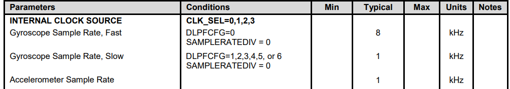
There is a significant issue: the accelerometer's sampling rate is limited to 1kHz, meaning 1ms sampling is the maximum. If you try to read the registers at a faster rate, you would likely receive the same data repeatedly. This is because the MPU-6050 updates the data in its FIFO buffer at 1ms intervals and provides the data when the MCU requests it.
Let's consider looking into other products.
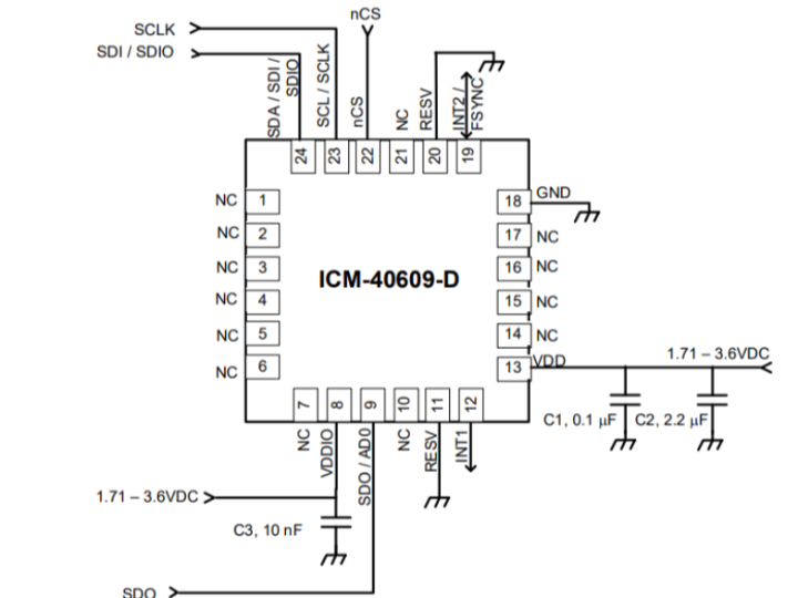
ICM-40609-D
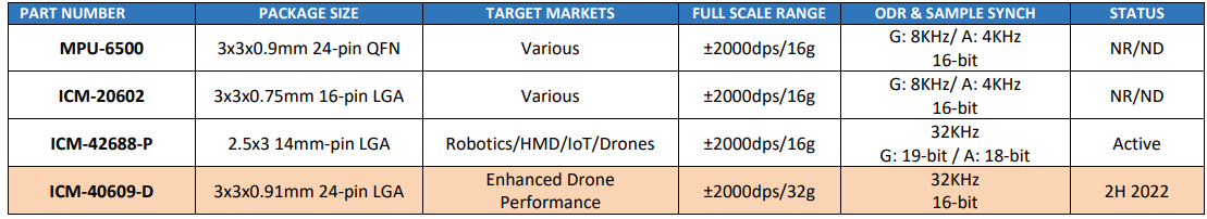
TDK’s product list, including the MPU-6050/9050, MPU-6500, and ICM-20602, indicates that these models are discontinued. Let’s look into the ICM-40609-D, which is reportedly used frequently in drones. It operates at 32kHz and 16-bit, making it a top-spec device in the current industry.
Like the MPU-6050, it samples data at 16 bits, but with a much faster speed of 32kHz, compared to the MPU-6050's 1kHz. Upon a brief review, it seems to offer 48-bit data for 3-axis gyroscope, 48-bit data for 3-axis accelerometer, and also includes bits for temperature and timestamp. When including the address, it totals around 120 bits, meaning it can sample 120 bits at a 32kHz rate.
Now, the question is how the I2C speed performs in handling this.
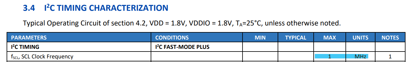
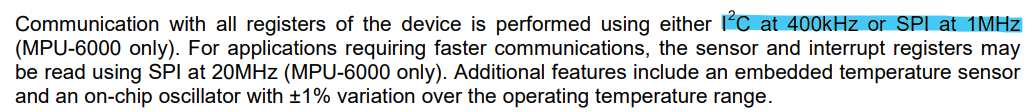
The I2C speed is 1MHz. Calculating 1M/120 = 8,333, this means that when receiving data via I2C, you can obtain sampled data at a maximum rate of 8.3kHz (including temperature and timestamp).
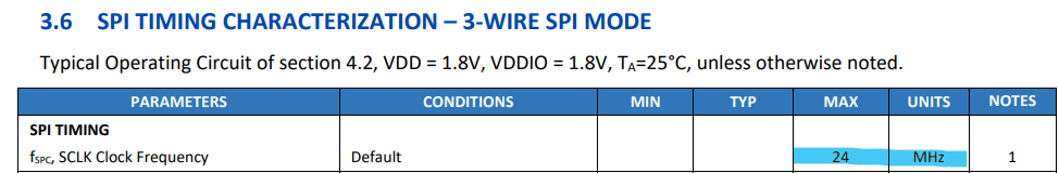
However, this chip can use SPI, allowing data transmission at a maximum speed of 24MHz. Unlike I2C, SPI does not require an address (ADDR), so subtracting about 8 bits leaves 112 bits. Based on this, you can roughly calculate that it can receive sampled data at around 200kHz.
I contacted the distributor. While there is plenty of information on TDK’s MPU6050 and 9250, there is almost no data available on other products, so I wanted to find a reliable alternative.
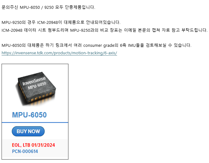
As expected, both the 6050 and 9250 are discontinued products. Although I received more information on the MPU-9250, I was able to find the product I needed through the replacement link for the MPU-6050.
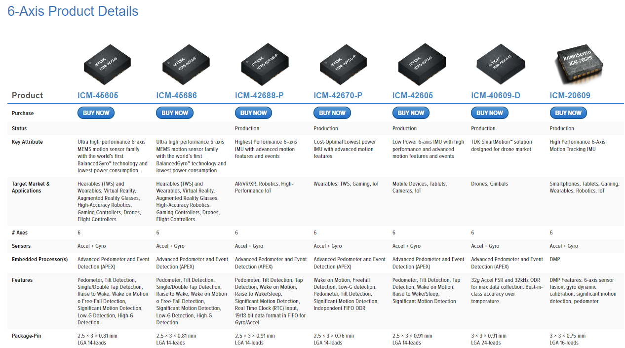
All six types of sensors supported both SPI and I2C. The best value for money was the ICM-40609-D, as expected. It also seemed to have the best stock availability (one of the few products with some documentation available).
Now, I plan to draw the circuit and work towards productization.
The problem is that I couldn't find the Artwork library anywhere, and while only the Package Dimensions were provided, there were no reference pad design documents. A 24-pin LGA... a package that can't be found anywhere.
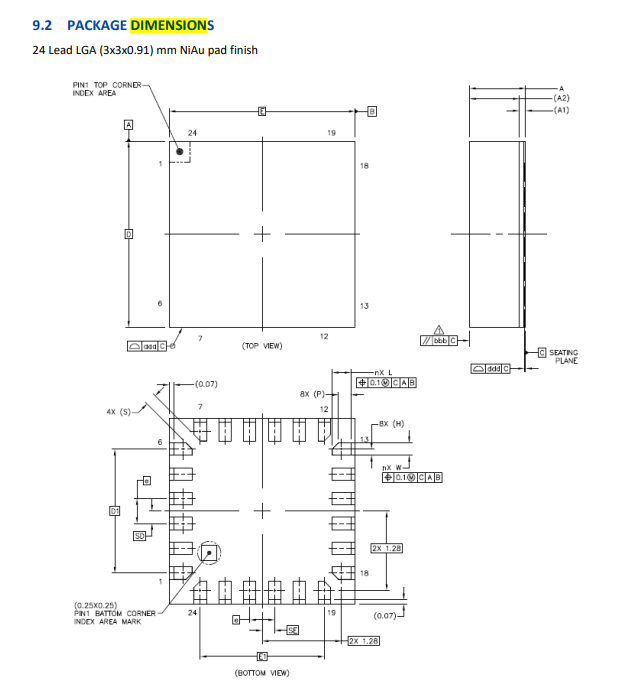
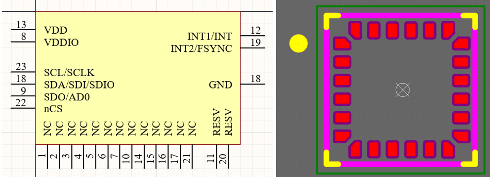
In the end, I had to painstakingly create it manually.
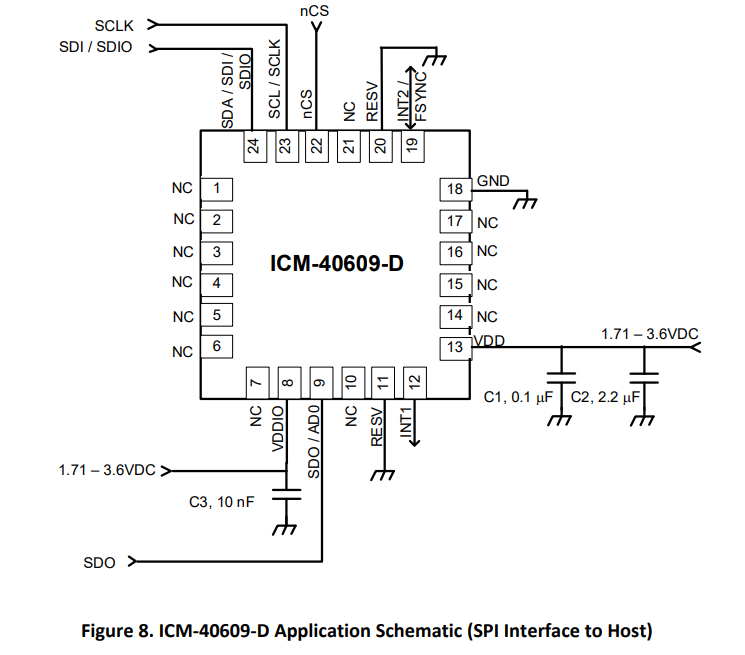
The circuit design is straightforward, as long as you connect the desired interfaces.
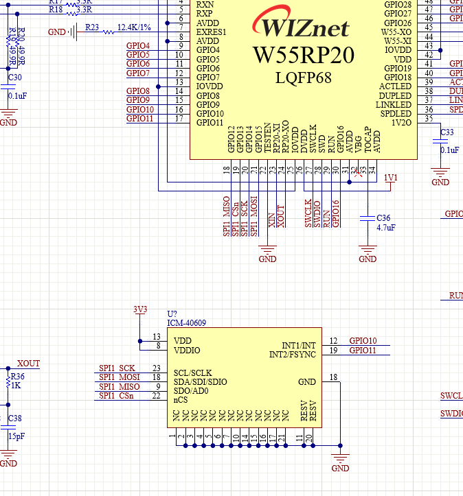
The W55RP20 is a chip that combines the RP2040 and W5500. I connected the ICM-40609-D to this chip as mentioned above. I chose SPI1 as the interface and completely disregarded I2C.
The circuit is roughly completed, and now it's time to start the Artwork process.