
Introduction
In this tutorial, we'll guide you through creating a simple Internet of Things (IoT) project where you can control multiple LEDs remotely using the W55RP20-EVB-Pico board and CircuitPython. This project utilizes TCP (Transmission Control Protocol) to establish communication between your device and a remote client over an Ethernet connection. If you're new to IoT or looking to explore new ways of controlling hardware over the internet, this project is a great starting point.
What is W55RP20-EVB-Pico?

The W55RP20-EVB-Pico is a development board powered by the W55RP20 microcontroller. It is designed specifically for Ethernet-based connectivity and IoT applications. This board provides various features like SPI communication, GPIO pins for interfacing with sensors and devices, and built-in Ethernet support, making it ideal for projects requiring wired network connectivity.
The W55RP20 microcontroller has built-in hardware support for Ethernet, allowing you to easily connect to networks and communicate with other devices. It also supports protocols like TCP/IP, making it an excellent choice for creating connected devices, such as smart lights, sensors, and control systems like the LED project we are building in this tutorial.
How It Works:
In this project, we will use the W55RP20-EVB-Pico to create a simple TCP server that controls LEDs. The basic flow of the project involves:
- Setting up the W55RP20-EVB-Pico to communicate over an Ethernet connection using CircuitPython.
- Writing a TCP server that listens for incoming connections from a remote client (such as your computer or mobile device).
- Receiving commands from the client (like "LED1 ON", "LED2 OFF") and controlling the LEDs accordingly.
- Sending a response back to the client confirming the action performed on the LEDs.
We'll also explore how this Ethernet-based communication works using TCP.
Gathering Components
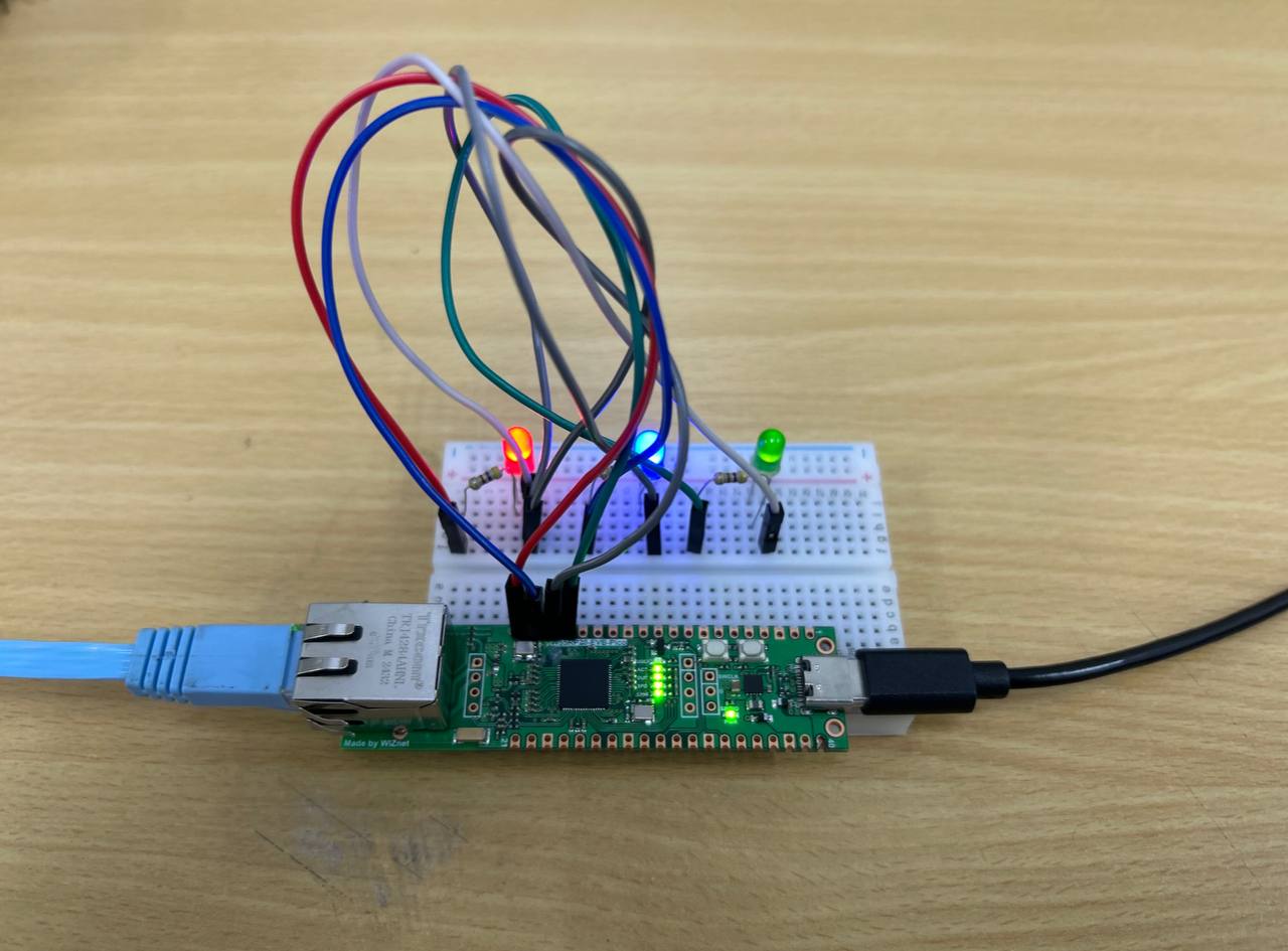
We are going to connect a 3 LED to the W55RP20-EVB-Pico. The LED will be controlled via GPIO (General Purpose Input/Output) pin and powered through the Pico’s 3.3V supply.
Here’s a detailed breakdown:
Components:
- W55RP20-EVB-Pico Board
- 1x USB Type-C cable
- 1x Ethernet Cable
- 3x 220Ω resistor
- 3x LED
- Jumper Wires
- Breadboard (Optional)
Schematic Diagram:

After completing the circuit setup, connect the W55RP20-EVB-Pico to your router or switch via an Ethernet cable and you are ready for the next step.
Flashing the Firmware (CircuitPython)
- To start, go to the CircuitPython page for the W55RP20-EVB-Pico. Scroll down to the "Downloads" section and click on the link to download the latest CircuitPython firmware for the board.
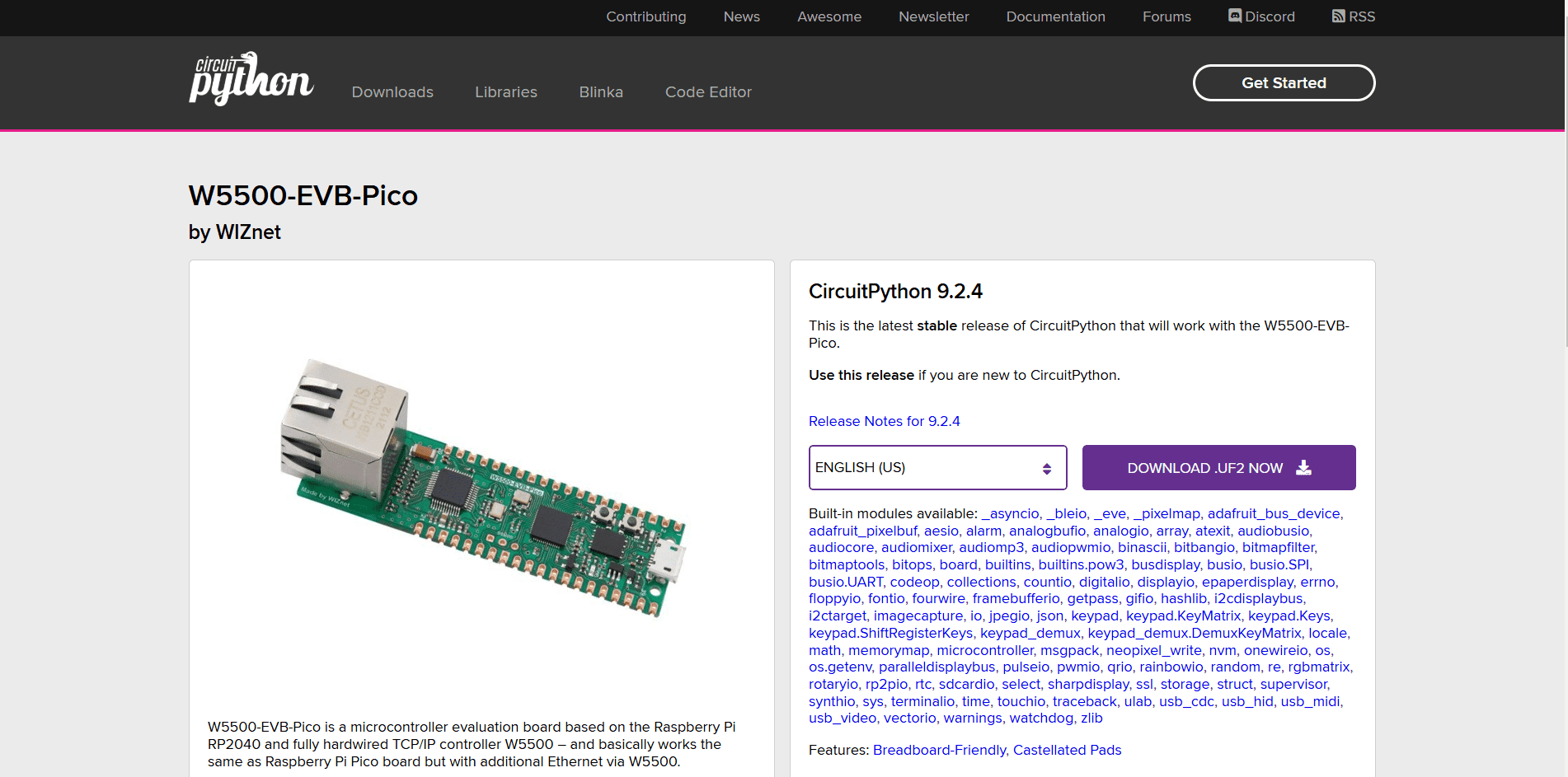
Simply download the .uf2 files for the board
Disclaimer: The board shown in the image is the W5500-EVB-Pico, which is not the same as the W55RP20-EVB-Pico that we are using in this tutorial. However, the firmware available on the CircuitPython page works the same for both boards.
- Once downloaded, you’ll need to put your W55RP20-EVB-Pico into bootloader mode. Press and hold the BOOTSEL button on the board, then press the RUN button once while connected to your computer via USB. The device will show up as an RPI-RP2 drive on your computer.
- Drag and drop the downloaded .uf2 firmware file onto the RPI-RP2 drive. The W55RP20-EVB-Pico will reboot automatically after the file is copied. When it resets, the drive will appear again as CIRCUITPY. The board is now running CircuitPython.
- To verify everything is working, open a Python editor (such as Thonny or Mu) and try running some simple code. Try this,
print("Hello, CircuitPython!")
Setup Libraries
To set up the required libraries for the W55RP20-EVB-Pico to work with the local network and additional functions. First, go to the WIZnet-ioNIC-Circuitpython GitHub repository’s libraries directory and download the following files:
- adafruit_pleasan.py
- adafruit_ticks.py
- wiznet5k.py
Next, open the CIRCUITPY drive and locate the lib folder inside the CIRCUITPY drive. Paste the downloaded files into the lib folder. Now you're all set!
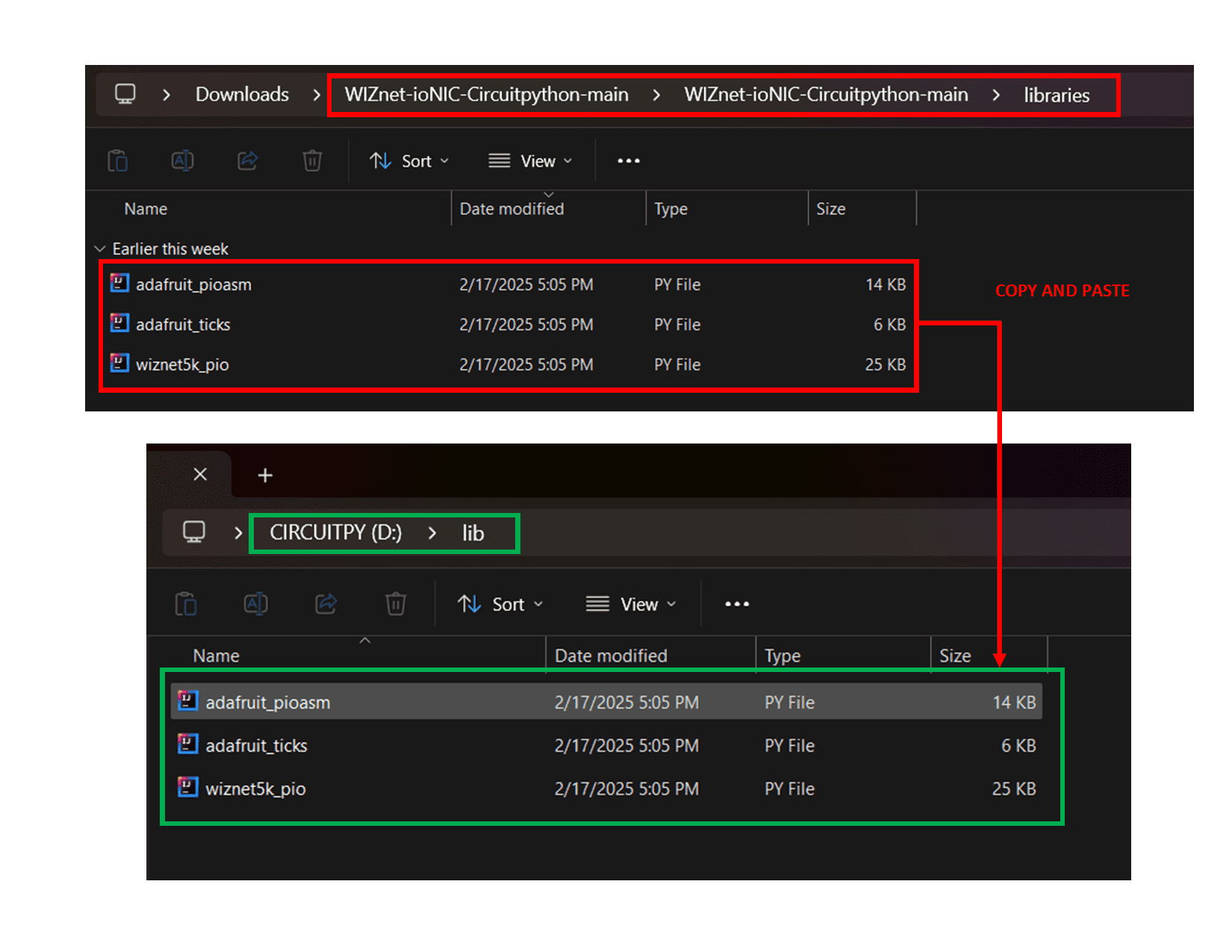
Simply copy the required libraries into the CIRCUITPY driver
Code
For this section, we will be using a TCP server to control the LED. Unlike the conventional method of using a webpage, we’ll be using Hercules, a TCP/UDP terminal client, to send commands.
Download here: Hercules SETUP Utility
Before diving into the actual LED control, let's first test TCP communication. You can use the sample code provided below to establish a basic TCP client-server setup. This will help you understand how data is sent and received over TCP. To communicate over TCP, you need to know your network's IP address, subnet mask, and gateway. Here's how to obtain that information:
- Connect the Ethernet cable from your W55RP20-EVB-Pico board to your laptop or computer.
- Open Command Prompt (Windows) or Terminal (Mac/Linux).
- Type the following command:
ipconfig
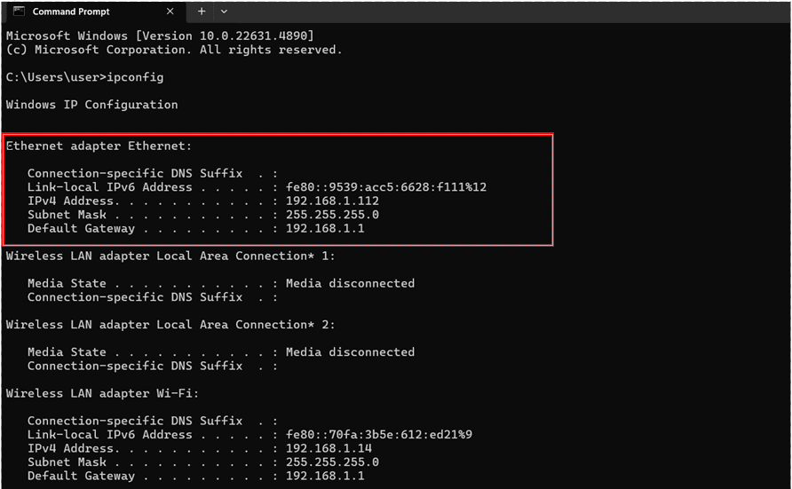
The IP address, subnet mask and the gateway for your network will be used in the code below
TCP Server Test Code
Reminder: Always check your network settings on your code before run the code!
import board
import rp2pio
import adafruit_pioasm
import digitalio
import time
from wiznet5k_pio import WIZNET5K
from adafruit_ticks import ticks_ms, ticks_diff
from micropython import const
from wiznet5k_pio import (
SNSR_SOCK_ESTABLISHED,
SNSR_SOCK_CLOSE_WAIT,
SNSR_SOCK_LISTEN,
SNSR_SOCK_CLOSED,
)
# PIO assembly code: SPI master implementation
spi_master = """
.program spi_master
pull block
set x, 7
bitloop:
out pins, 1
set pins, 1
nop [1]
in pins, 1
set pins, 0
jmp x-- bitloop
push block
"""
#Change the ip_address, gateway_ip and subnet_mask with your own network information
mac_address = [0x00, 0x08, 0xDC, 0x01, 0x02, 0x03]
ip_address = [192, 168, 11, 110]
gateway_ip = [192, 168, 11, 1]
subnet_mask = [255, 255, 255, 0]
# PIO and State Machine setup
assembled = adafruit_pioasm.assemble(spi_master)
sm = rp2pio.StateMachine(
assembled,
frequency=1_000_000,
first_out_pin=board.GP23, # mosi
first_in_pin=board.GP22, # miso
first_set_pin=board.GP21, # clk
out_pin_count=1,
in_pin_count=1,
set_pin_count=1,
in_shift_right=False,
out_shift_right=False,
push_threshold=8,
pull_threshold=8,
)
# CS and RST pin setup
cs_pin = digitalio.DigitalInOut(board.GP20)
rst_pin = digitalio.DigitalInOut(board.GP25)
# Initialize WIZNET5K
wiznet = WIZNET5K(
sm,
cs_pin,
rst_pin,
mac_address=mac_address,
ip_address=ip_address,
gateway_ip=gateway_ip,
subnet_mask=subnet_mask,
)
# After creating the WIZNET5K instance
version = wiznet.read_version()
print(f"W5500 Version: 0x{version:02X}")
print("Network information :", wiznet.ifconfig)
## TCP
# Initialize socket and start listening (MAX socket < 8)
sock_num_tcp = 0
port_tcp = 5000
print("Socket Open (TCP)")
wiznet.socket_init(sock_num_tcp)
wiznet.socket_listen(sock_num_tcp, port_tcp)
print(f"Listening on TCP port {port_tcp}")
while True:
# Handle TCP socket
status_tcp = wiznet.socket_status(sock_num_tcp)
if status_tcp == SNSR_SOCK_ESTABLISHED: # SOCK_ESTABLISHED
# Receive data from the client
data = wiznet.socket_recv(sock_num_tcp)
if data:
remote_port = wiznet.remote_port(sock_num_tcp)
print(f"[TCP] Dest P: {remote_port} Received: {data}")
# Echo the data back to the client
wiznet.socket_send(sock_num_tcp, data)
elif status_tcp == SNSR_SOCK_CLOSE_WAIT: # SOCK_CLOSE_WAIT
print("[TCP] Client disconnected, closing socket")
wiznet.socket_close(sock_num_tcp)
wiznet.socket_init(sock_num_tcp)
wiznet.socket_listen(sock_num_tcp, port_tcp)
elif status_tcp == SNSR_SOCK_LISTEN: # SOCK_LISTEN
pass # Listening for incoming connections
elif status_tcp == SNSR_SOCK_CLOSED: # SOCK_CLOSED
wiznet.socket_init(sock_num_tcp)
wiznet.socket_listen(sock_num_tcp, port_tcp)
Now, open Hercules to send simple TCP commands to the server. In Hercules, set it to TCP Client mode and input the following:
- Server IP address: Enter the IP address you obtained earlier.
- Port: Set it to the port number you're using
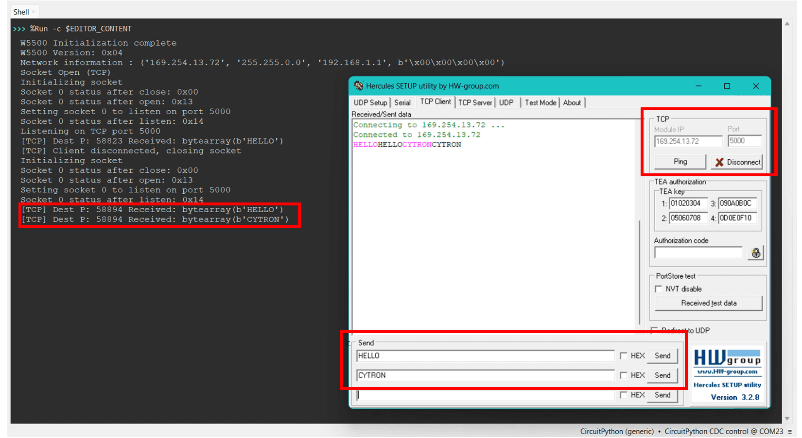
The communication between a TCP server (on the W55RP20-EVB-Pico) and a client (using Hercules software). The server receives the messages "HELLO" and "CYTRON" from Hercules, which are displayed in the terminal.
Once you've successfully established basic TCP communication, let's move to the next step—controlling the LED.
We will send specific commands to the W55RP20-EVB-Pico to turn on/off or change the color of the LED by controlling the GPIO pins based on the commands sent from Hercules. Simply use the provided code below:
TCP Server LED Control Code
Reminder: Always check your network settings on your code before run the code!
import board
import rp2pio
import adafruit_pioasm
import digitalio
import time
from wiznet5k_pio import WIZNET5K
from adafruit_ticks import ticks_ms, ticks_diff
from micropython import const
from wiznet5k_pio import (
SNSR_SOCK_ESTABLISHED,
SNSR_SOCK_CLOSE_WAIT,
SNSR_SOCK_LISTEN,
SNSR_SOCK_CLOSED,
)
# PIO assembly code: SPI master implementation
spi_master = """
.program spi_master
pull block
set x, 7
bitloop:
out pins, 1
set pins, 1
nop [1]
in pins, 1
set pins, 0
jmp x-- bitloop
push block
"""
# Network settings
mac_address = [0x00, 0x08, 0xDC, 0x01, 0x02, 0x03]
ip_address = [169, 254, 13, 72] # Modify to match your network
gateway_ip = [192, 168, 1, 1]
subnet_mask = [255, 255, 0, 0]
# PIO and State Machine setup
assembled = adafruit_pioasm.assemble(spi_master)
sm = rp2pio.StateMachine(
assembled,
frequency=1_000_000,
first_out_pin=board.GP23, # mosi
first_in_pin=board.GP22, # miso
first_set_pin=board.GP21, # clk
out_pin_count=1,
in_pin_count=1,
set_pin_count=1,
in_shift_right=False,
out_shift_right=False,
push_threshold=8,
pull_threshold=8,
)
# CS and RST pin setup
cs_pin = digitalio.DigitalInOut(board.GP20)
rst_pin = digitalio.DigitalInOut(board.GP25)
# Initialize WIZNET5K
wiznet = WIZNET5K(
sm,
cs_pin,
rst_pin,
mac_address=mac_address,
ip_address=ip_address,
gateway_ip=gateway_ip,
subnet_mask=subnet_mask,
)
# After creating the WIZNET5K instance
version = wiznet.read_version()
print(f"W5500 Version: 0x{version:02X}")
print("Network information :", wiznet.ifconfig)
## LED setup
led_pin_1 = digitalio.DigitalInOut(board.GP15) # LED 1
led_pin_2 = digitalio.DigitalInOut(board.GP14) # LED 2
led_pin_3 = digitalio.DigitalInOut(board.GP13) # LED 3
led_pin_1.direction = digitalio.Direction.OUTPUT
led_pin_2.direction = digitalio.Direction.OUTPUT
led_pin_3.direction = digitalio.Direction.OUTPUT
led_pin_1.value = False # Start with all LEDs off
led_pin_2.value = False
led_pin_3.value = False
## TCP
sock_num_tcp = 0
port_tcp = 5000
print("\nServer is ready to accept commands...")
print(f"Listening on TCP port {port_tcp}...")
while True:
# Handle TCP socket
status_tcp = wiznet.socket_status(sock_num_tcp)
if status_tcp == SNSR_SOCK_ESTABLISHED: # SOCK_ESTABLISHED
# Receive data from the client
data = wiznet.socket_recv(sock_num_tcp)
if data:
remote_port = wiznet.remote_port(sock_num_tcp)
print(f"\n[Client connected: Port {remote_port}]")
# Handle LED control based on received command
command = data.strip().decode().upper() # Normalize command to uppercase for consistency
if command == "LED1 ON":
led_pin_1.value = True
response = "LED 1 ON: The first LED has been powered ON successfully."
elif command == "LED1 OFF":
led_pin_1.value = False
response = "LED 1 OFF: The first LED has been powered OFF successfully."
elif command == "LED2 ON":
led_pin_2.value = True
response = "LED 2 ON: The second LED has been powered ON successfully."
elif command == "LED2 OFF":
led_pin_2.value = False
response = "LED 2 OFF: The second LED has been powered OFF successfully."
elif command == "LED3 ON":
led_pin_3.value = True
response = "LED 3 ON: The third LED has been powered ON successfully."
elif command == "LED3 OFF":
led_pin_3.value = False
response = "LED 3 OFF: The third LED has been powered OFF successfully."
else:
response = "Invalid command: Please send 'LED1 ON', 'LED1 OFF', 'LED2 ON', 'LED2 OFF', 'LED3 ON', or 'LED3 OFF' to control the LEDs."
# Send formatted response back to the client
response_header = "\n******************************\n"
response_footer = "\n******************************"
formatted_response = f"{response_header}Command received: {command}\n{response}{response_footer}"
wiznet.socket_send(sock_num_tcp, formatted_response.encode())
elif status_tcp == SNSR_SOCK_CLOSE_WAIT: # SOCK_CLOSE_WAIT
print("[TCP] Client disconnected, closing socket")
wiznet.socket_close(sock_num_tcp)
wiznet.socket_init(sock_num_tcp)
wiznet.socket_listen(sock_num_tcp, port_tcp)
elif status_tcp == SNSR_SOCK_LISTEN: # SOCK_LISTEN
pass # Listening for incoming connections
elif status_tcp == SNSR_SOCK_CLOSED: # SOCK_CLOSED
wiznet.socket_init(sock_num_tcp)
wiznet.socket_listen(sock_num_tcp, port_tcp)
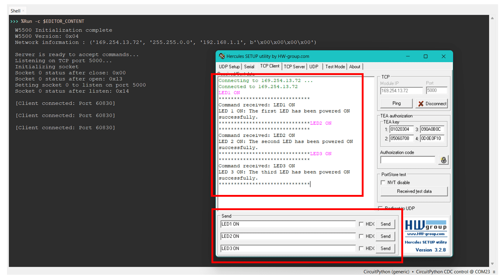
The server successfully receives and responds to the commands sent from Hercules, such as "LED1 ON", "LED2 ON", and "LED3 ON"
Expected output from the hardware setup