Power-on operation routine for W55RP20
Power-on operation routine for W55RP20

I want to learn about the power-on sequence of the W55RP20.

W55RP20 Power-On Operation Sequence
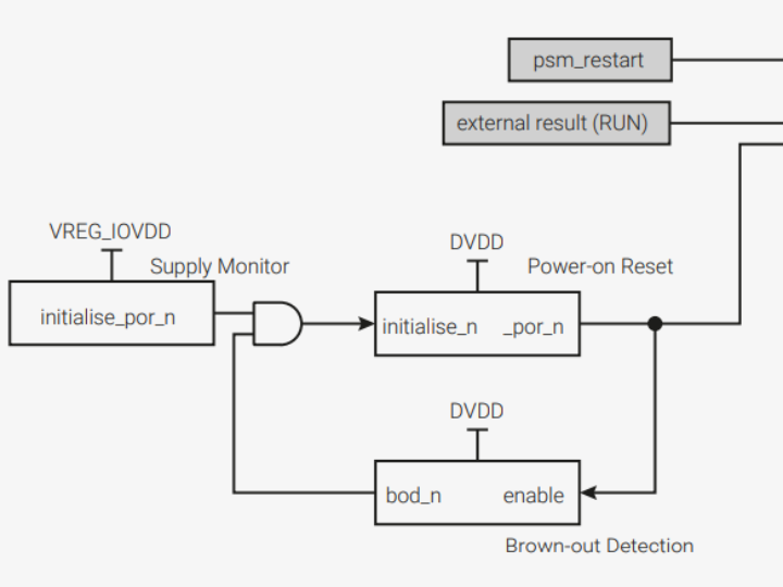
Scenario 1: Upon power-on, VREG_IOVDD (3.3V) is supplied first. At this stage, the internal regulator has not yet generated the core voltage DVDD (1.1V).


Here, Brown-Out Detection is triggered, monitoring the voltage level of DVDD. If it drops below DVDD.BOD.TH, the bod_n signal goes low. This threshold can be set via the BOD register. This mechanism helps prevent unpredictable behavior caused by unstable power supply.
As a result, bod_n becomes 0, and consequently, _por_n also becomes 0. Thus, rst_n_psm remains at 0.
Scenario 2: When both VREG_IOVDD and DVDD are stable

When VREG_IOVDD and DVDD are stable, the final _por_n signal becomes 1..

This causes rst_n_psm to also operate at 1, activating the PSM.
Below is a timing graph summarizing the above process.
Once DVDD stabilizes, por_n is released, and the PSM operates normally. If DVDD voltage drops, the Brown-Out Detection mechanism detects it, activates the Power-On Reset, and lowers por_n. Later, when DVDD becomes stable again, por_n automatically rises.
# Even without the Brown-Out Detection feature, the Power-On Reset would likely activate por_n to Low if DVDD drops significantly. However, incorporating the Brown-Out Detection feature allows users to manage power stability through register-configurable settings.

Circuit Design Considerations
Even with the POR and BOD protection circuits, issues can arise during W55RP20 booting.
If the timing of the DVDD supply is off or unstable due to noise, por_n may output 1 prematurely, causing boot issues for the W55RP20. To address such scenarios, delaying the voltage rise of the RUN pin can help.
(Regardless of internal POR noise or issues, delaying RUN prevents PSM from operating during that period.)
Power-On State Machine
Once the protection circuit completes its operation and rst_n_psm is released high, the Power-On State Machine routine begins.

The Power-On State Machine (PSM) in the W55RP20 initializes the chip hardware in a specific sequence whenever power is applied or reset. Key steps include:
Initialization Sequence:
- Once the digital core voltage (DVDD) stabilizes and the RUN pin activates, the chip-level reset subsystem releases the reset signal.
- The ring oscillator starts first, while the crystal oscillator remains inactive.
- The clock generators (clk_ref, clk_sys) activate using the ring oscillator as the initial clock source.
Key Initialization Steps:
- Reset Controller: Manages the reset of all peripherals.
- Chip-Level Reset and Voltage Regulator: Manages boot state and subsystem resets.
- XIP (Execute-In-Place): Enables code execution directly from external SPI flash.
- ROM and SRAM: Boot ROM is initialized, and SRAM is made available.
- Bus Fabric: Establishes communication between the processor and peripherals.
- Processor Complex: Both cores are reset and prepared, with proc1 entering sleep mode and proc0 executing boot code.
Automated Operation:
The PSM operates fully automatically without user intervention. For debugging, functionality to control or verify its operation via registers is also provided.
