
smart-bell
atmega328 smart-bell

WIZnet - W5500
x 1
📌 Overview
이 프로젝트는 AVR ATmega328P 마이크로컨트롤러를 기반으로 한 스마트 초인종(Smart Bell) 펌웨어 예제로, 버튼 입력을 인터럽트로 처리하고 타이머 기반 제어를 통해 출력 장치를 구동하는 구조를 갖고 있습니다. UART를 이용한 디버그 인터페이스와 SPI 통신 계층을 기본으로 포함하고 있으며, W5500 이더넷 컨트롤러와 같은 외부 통신 칩을 연동할 수 있도록 확장 가능한 구조로 설계되었습니다.
📌 Features
- 외부 인터럽트(INT0)를 이용한 버튼 입력 처리
- 타이머 인터럽트 기반의 벨 출력 시간 제어
- 출력 핀(PB0)을 통한 부저, 릴레이, LED 등 제어 가능
- UART 기반 시리얼 디버그 및 데이터 에코 기능
- SPI 통신 인터페이스 제공 (W5500 등 외부 칩 연동 가능)
- Watchdog Timer(WDT) 설정을 통한 시스템 안정성 확보
- C++ 기반 모듈화 구조로 가독성과 확장성 강화
- Circular Buffer 등 재사용 가능한 유틸리티 포함
- CMake + Conan 기반의 현대적인 임베디드 빌드 환경
- 유닛 테스트 코드 포함으로 유지보수 및 검증 용이
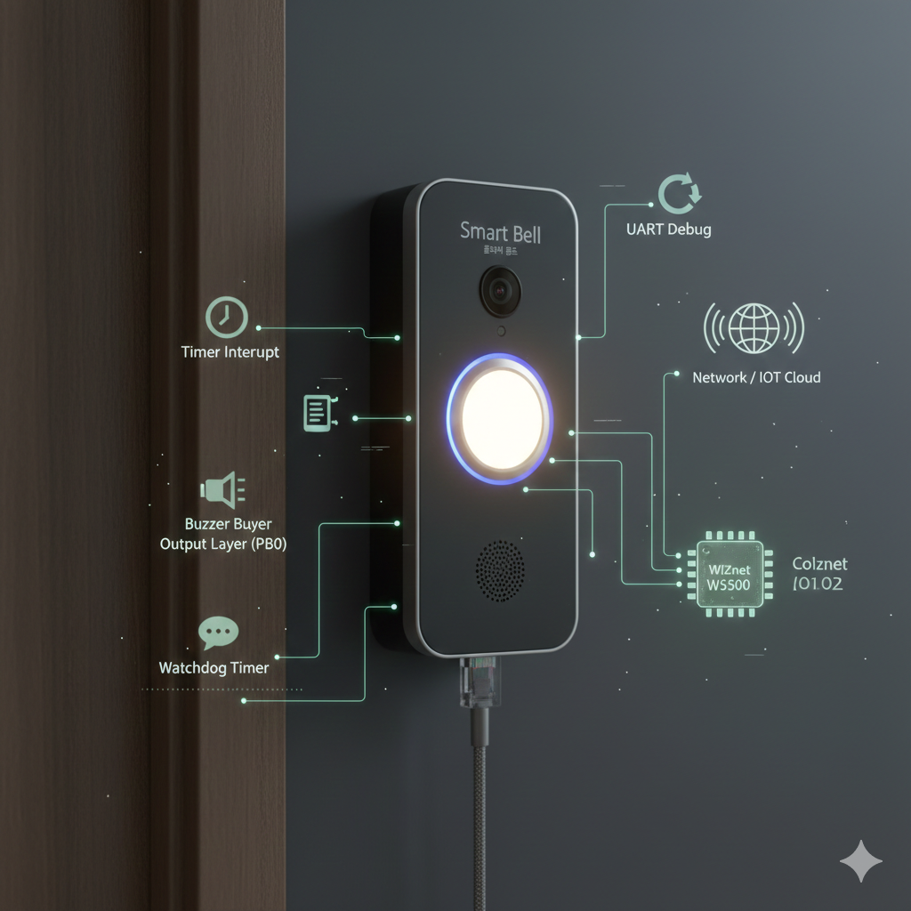
📌 System Architecture
- MCU (ATmega328P)
- 인터럽트, 타이머, GPIO, 통신 제어의 중심 역할 수행
- Input Layer
- 외부 버튼 입력을 INT0 인터럽트로 감지
- Control Logic
- 인터럽트 이벤트 기반 상태 제어
- 타이머 카운트를 이용한 벨 동작 시간 관리
- Output Layer
- GPIO(PB0)를 통한 벨/릴레이/LED 출력 제어
- Communication Layer
- UART: 디버그 메시지 출력 및 시리얼 통신
- SPI: W5500 이더넷 컨트롤러 등 외부 디바이스 연동용 인터페이스
- System Services
- Watchdog Timer를 통한 시스템 리셋 및 오류 복구
📌 Role and Application of the WIZnet's Chip
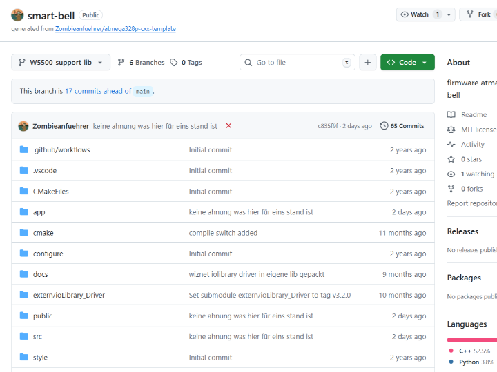
Source Link : https://github.com/Zombieanfuehrer/smart-bell/blob/W5500-support-lib/app/smart_bell_main.cpp
사용된 WIZnet 칩 모델명: W5500
네트워크에서의 역할:
- SPI 인터페이스를 통해 MCU와 연결되어 Ethernet 통신의 물리 계층 및 전송 계층(TCP/UDP)을 독립적으로 처리
- MCU는 소켓 제어 및 데이터 송수신 명령만 수행함으로써 펌웨어 복잡도와 CPU 부하를 최소화
- 초인종 이벤트 발생 시, 네트워크를 통해 이벤트 알림, 상태 전송, 원격 모니터링 기능을 구현할 수 있는 통신 엔드포인트 역할
- 안정적인 하드웨어 TCP/IP 처리로 임베디드 환경에서도 예측 가능한 네트워크 동작과 높은 신뢰성 확보
📌 Market & Application Value
(by ChatGPT)
적용 가능한 산업 및 시장
- 주거/소형 상가: 출입 알림(벨/인터폰 보조), 방문 이벤트 로그
- 무인 매장/창고/사무실: 출입 이벤트 기록 + 원격 알림
- 산업 현장: 호출벨(Andon), 안전/비상 호출, 설비 이벤트 트리거 전송
- “스마트 벨”은 기능을 붙이기 시작하면 로그(이력), 사용자 관리, 알림 채널 다중화(앱/메신저), 장치 원격 설정으로 서비스화가 가능
📌 Summary
본 프로젝트는 ATmega328P 기반의 스마트 초인종 구현을 통해 인터럽트와 타이머를 활용한 안정적인 이벤트 제어 구조를 제시합니다. UART와 SPI 통신 계층을 포함한 확장 가능한 펌웨어 구조로 설계되어, 단순한 로컬 장치를 네트워크 기반 IoT 디바이스로 확장할 수 있습니다. WIZnet의 W5500 이더넷 컨트롤러는 하드웨어 TCP/IP 처리를 통해 MCU의 부담을 줄이고 안정적인 네트워크 통신을 가능하게 합니다. 이를 통해 초인종 이벤트를 원격으로 전송하고 모니터링할 수 있는 IoT 응용이 가능합니다.
📌 FAQ
Q1. 왜 Smart Bell 프로젝트에서 WIZnet W5500을 사용하나요?
A: W5500은 하드웨어 TCP/IP 스택을 내장한 이더넷 컨트롤러로, MCU가 네트워크 프로토콜을 직접 처리하지 않아도 됩니다. Smart Bell과 같은 알림 시스템은 버튼 입력 후 서버 전송까지의 지연과 안정성이 중요하며, W5500은 Wi-Fi 대비 패킷 손실과 지터(jitter)가 거의 없는 유선 통신을 제공합니다. 이로 인해 CPU 부하 감소와 예측 가능한 동작을 동시에 달성할 수 있습니다.
Q2. W5500은 이 Smart Bell 프로젝트에서 어떤 역할을 하나요?
A: 이 프로젝트에서 W5500은 네트워크 전송 계층(Network Transport Layer) 역할을 담당합니다. 벨 입력 이벤트가 발생하면 MCU는 W5500을 통해 서버 또는 로컬 네트워크로 데이터를 전송합니다. TCP/UDP 소켓 관리, 재전송, 연결 유지 등의 작업은 W5500 하드웨어가 처리하므로, MCU는 입력 처리와 애플리케이션 로직에 집중할 수 있습니다.
Q3. MCU와 W5500은 어떻게 연결되나요?
A: W5500은 SPI 인터페이스로 MCU와 연결됩니다. 기본적으로 MOSI, MISO, SCK, CS의 4개 신호선만 필요하며, 인터럽트(INT) 핀을 사용하면 이벤트 기반 통신도 가능합니다. 이 구조는 핀 수가 제한된 MCU에서도 Ethernet 기능을 쉽게 추가할 수 있어, Smart Bell 같은 소형 임베디드 장치에 적합합니다.
Q4. Wi-Fi 대신 Ethernet(W5500)을 사용한 이유는 무엇인가요?
A: Smart Bell은 “항상 동작해야 하는” 장치이기 때문에 연결 안정성이 핵심입니다. Wi-Fi는 전파 간섭, AP 재연결, 전원 관리 이슈로 인해 지연이나 연결 끊김이 발생할 수 있습니다. 반면 W5500 기반 Ethernet은 전원 인가 후 즉시 링크 업, 1ms 단위의 안정적인 응답, 네트워크 환경 변화에 덜 민감한 특성을 제공하여 상시 대기형 IoT 장치에 유리합니다.
Q5. 이 프로젝트를 W55RP20으로도 구현할 수 있나요?
A: 네, 가능합니다. W55RP20은 RP2040 MCU와 W5500을 단일 칩으로 통합한 제품으로, Smart Bell과 같은 프로젝트에 특히 적합합니다. 별도의 MCU + Ethernet 칩 구성 대비 BOM 비용 감소, PCB 면적 축소, SPI 배선 제거로 신뢰성 향상이라는 장점이 있습니다. 기능적으로는 기존 W5500 기반 구조와 동일하게 동작합니다.
📌 Overview
This project is a smart doorbell (Smart Bell) firmware example based on the AVR ATmega328P microcontroller, featuring a structure in which button inputs are handled via interrupts and output devices are driven through timer-based control. It includes a UART-based debug interface and an SPI communication layer by default, and is designed with an expandable architecture that allows integration with external communication chips such as the W5500 Ethernet controller.
📌 Features
- Button input handling using an external interrupt (INT0)
- Bell output duration control based on timer interrupts
- Control of buzzer, relay, LED, etc. via an output pin (PB0)
- UART-based serial debugging and data echo functionality
- SPI communication interface provided (enabling integration with external chips such as the W5500)
- System stability ensured through Watchdog Timer (WDT) configuration
- Improved readability and extensibility through a C++-based modular structure
- Inclusion of reusable utilities such as a circular buffer
- Modern embedded build environment based on CMake and Conan
- Included unit test code for easier maintenance and verification
📌 System Architecture
- MCU (ATmega328P)
- Acts as the central controller for interrupts, timers, GPIO, and communication control
- Input Layer
- Detects external button input via the INT0 interrupt
- Control Logic
- State control based on interrupt events
- Management of bell operation time using timer counts
- Output Layer
- Controls bell/relay/LED output via GPIO (PB0)
- Communication Layer
- UART: Debug message output and serial communication
- SPI: Interface for connecting external devices such as the W5500 Ethernet controller
- System Services
- System reset and error recovery through the Watchdog Timer
📌 Role and Application of the WIZnet's Chip
Source Link : https://github.com/Zombieanfuehrer/smart-bell/blob/W5500-support-lib/app/smart_bell_main.cpp
WIZnet chip model used: W5500
Role in the network:
- Connected to the MCU via an SPI interface and independently handles the physical layer and transport layer (TCP/UDP) of Ethernet communication
- By having the MCU perform only socket control and data transmission/reception commands, firmware complexity and CPU load are minimized
- Serves as a communication endpoint that enables event notifications, status transmission, and remote monitoring over the network when a doorbell event occurs
- Ensures predictable network behavior and high reliability in embedded environments through stable hardware-based TCP/IP processing
📌 Market & Application Value
(by ChatGPT)
Applicable industries and markets
- Residential / small retail spaces: Entry notifications (bell/intercom support), visitor event logging
- Unmanned stores / warehouses / offices: Access event recording and remote notifications
- Industrial sites: Call buttons (Andon), safety/emergency calls, transmission of equipment event triggers
- As a “smart bell” evolves by adding features, it can be developed into a service through event logging (history), user management, multi-channel notifications (apps/messengers), and remote device configuration
📌 Summary
This project presents a stable event control architecture using interrupts and timers through the implementation of a smart doorbell based on the ATmega328P. Designed with an extensible firmware structure that includes UART and SPI communication layers, it enables a simple local device to be expanded into a network-based IoT device. WIZnet’s W5500 Ethernet controller reduces the processing burden on the MCU through hardware-based TCP/IP handling and enables reliable network communication. As a result, IoT applications that remotely transmit and monitor doorbell events can be realized.
📌 FAQ
Q1. Why is the WIZnet W5500 used in the Smart Bell project?
A: The W5500 is an Ethernet controller with an embedded hardware TCP/IP stack, allowing the MCU to operate without directly handling network protocols. In notification systems like Smart Bell, low latency and high reliability from button input to server transmission are critical. Compared to Wi-Fi, the W5500 provides wired communication with virtually no packet loss or jitter, enabling both reduced CPU load and predictable system behavior.
Q2. What role does the W5500 play in this Smart Bell project?
A: In this project, the W5500 serves as the network transport layer. When a bell input event occurs, the MCU sends data to a server or local network via the W5500. Tasks such as TCP/UDP socket management, retransmission, and connection maintenance are handled by the W5500 hardware, allowing the MCU to focus on input handling and application logic.
Q3. How are the MCU and W5500 connected?
A: The W5500 is connected to the MCU via an SPI interface. Basically, only four signal lines—MOSI, MISO, SCK, and CS—are required, and event-driven communication is also possible using the interrupt (INT) pin. This structure makes it easy to add Ethernet functionality even to MCUs with limited pin counts, making it well suited for compact embedded devices like Smart Bell.
Q4. Why was Ethernet (W5500) chosen instead of Wi-Fi?
A: Smart Bell is an “always-on” device, so connection stability is essential. Wi-Fi can suffer from delays or disconnections due to radio interference, AP reconnections, and power management issues. In contrast, W5500-based Ethernet offers immediate link-up after power-on, stable responses on the order of 1 ms, and lower sensitivity to network environment changes, making it more suitable for always-ready IoT devices.
Q5. Can this project also be implemented with the W55RP20?
A: Yes, it can. The W55RP20 integrates an RP2040 MCU and a W5500 into a single chip, making it particularly suitable for projects like Smart Bell. Compared to a separate MCU + Ethernet chip configuration, it offers advantages such as reduced BOM cost, smaller PCB area, and improved reliability by eliminating SPI wiring. Functionally, it operates in the same way as an existing W5500-based architecture.