

Running experiments has been a big part of my electronics hobby and having test equipment is quite important to making that happen. While I am most fortunate to have been involved in many element14 RoadTests and have had equipment donated by vendors over time, amassing a cache of equipment, the price of equipment can put them out of reach of mere mortals. Being one to review products, I don’t usually get to pick and choose, so I usually have to make do with what I have as my pockets aren’t exactly lined with cash either. Other times, you realise that you just can’t buy something that you need because it doesn’t exist on the market.
It’s been a while since I last embarked on a big project and having just finished my blog series on the element14 Experimenting with Thermistors Design Challenge, this inspired me to try and build something new, being my first project that makes use of the inexpensive and fairly powerful Raspberry Pi RP2040 microcontroller.
The Problem
The Experimenting with Thermistors Design Challenge threw up a common problem that any experimenter is likely to experience sooner or later. If you have an array of different signals you want to measure quite accurately, how do you do this cost-effectively?
The most naive approach is to hook each signal into its own 5.5-digit or better bench-top digital multimeter, but that would be extremely costly and results will be vulnerable to differences in calibration between meters.
Another approach is to give up on measuring signals in parallel, and instead, run your experiments sequentially by testing one item after another. While this is a reasonable approach for some experiments, this is not ideal for others and also means more overhead in experimental set-up and teardown.
There are multi-input process monitors such as the B&K Precision DAS240-BAT which could fit the bill, offering many input channels and a fairly brisk sequential sampling rate but such devices usually are not as accurate as a 5.5-digit or better digital multimeter. They’re not exactly inexpensive either and buying more equipment is usually out of the question.
Many will give-up and instead change signals by hand, perhaps making only limited numbers of measurements. This is perhaps the least preferable outcome, as it means a lot of manual intervention and a lack of automation. Ideally, you want the hard work to be done for you.
The industry’s solution to this problem is to have a scanner system. This could mean a Keithley 2000-series scanning DMM, or its more modern DMM6500 counterpart, or a Keysight DAQ970A data acquisition system. This essentially has a highly accurate DMM paired with interchangeable multiplexer cards which allow the inputs to be automatically switched. While the DMM6500 and DAQ970A were both offered for RoadTest, my applications were unsuccessful.
To make complete those systems requires purchasing switching modules. A 10-input two-pole card for the Keithley (2000-SCAN) is priced at AU$1312.70, while a 20-input two-pole solid-state module for the Keysight (DAQM900A) is priced at AU$1157.53. As a result, the cost of a system can add up quite quickly and this isn’t exactly economical for a hobbyist.
As a result, I rely mostly on a Keithley 2110 and a Keysight EDU34450A 5.5-digit DMMs, both of which are not equipped with the possibility of scanner expansion.

One way around this was to develop my own 10-channel two-pole scanner shield using signal relays, an Arduino Uno, Ethernet Shield. This took two attempts as my first attempt had a critical PCB error, but the resulting device was quite effective in helping me complete my Experimenting with Thermistors Design Challenge. The main downsides were the 10-input limitation and the fact that mechanical relays have a finite lifetime. Another is just the acoustics of having relays clicking away constantly in the room.
As a result, I decided that I needed to go bigger and to go solid-state – essentially building a scanner that was standalone using the same kind of solid-state OptoMOS relays that the DAS240-BAT was using.
Designing a Solution
To design a scanner or multiplexer is perhaps not a new thing. In fact, for those who might balk at the price for a 2000-SCAN, there are projects including the CozScan2020 and this one from George Christidis which are a design for a 20-channel solid-state-relay version of the card. Just one problem … I don’t have a DMM6500 and I don’t think I’m going to buy one for myself in a hurry (even though I did get one for my university lab).
Not having looked around first, I decided to embark on my own standalone design from scratch. This started with searching for components that would best meet my needs and were available. The component shortages makes for a rather desperate situations!

In the end, the schematic looks as above – ignore the relay model number as I chose an Omron G3VM-61VY3 instead. The key design choices were as follows:
- A system that would allow for one-wire, two-wire or four-wire operation. This means the system could do 40 inputs with one-wire switching, or 20 inputs for two-wire switching, or 10 inputs for four-wire switching for maximum versatility. The downside to this is that the input terminal ordering is not optimally convenient for connections as positive and negative poles may be separated by a distance.
- The system should protect the relatively pricey solid-state relays. As a result, each input is protected by a polyfuse even if this means an increased and potentially varying channel resistance. This should also protect against the case of mis-operation of the relays due to a code fault or execution error and maintain safety.
- The system should prioritise low-resistance solid-state relays, maintaining at least 48V channel voltage capability. The selection of this particular model of relay meets this requirement.
- Relays should be driven with about 5-8mA forward current, expecting about 1.2V drop from its IR LED. Low currents below 3mA may not result in reliable activation, while higher currents above 8mA will likely shorten lifetime and accelerate LED degradation. Resistance is chosen so that (likely) when combined with the digital I/O resistance, the current will be within the target range.
- The system can only use components that can be purchased – originally, I wanted to stick with my favourite MCP23017 port expanders, but they were out of stock with a long lead time. Changing over to the PCA9535 was a compromise.
- The system can be expandable in some way by exposing the I2C bus for other sensors – at the least, it can host a BMP280 environmental sensor just for temperature and pressure readings.
- The system should have USB-CDC and Ethernet LAN-SOCKET connectivity. To ensure this requirement is met, I used a Wiznet W5100S-EVB-PICO board that has a similar footprint to the Raspberry Pi Pico but integrates the Ethernet controller and interface hardware. This means it will operate as its own standalone “instrument” compatible with any measurement device.
- Switching speed is not a major priority, although faster switching is desirable as long as safety can be maintained.
The design has a row of terminals which are commoned together for use with single-wire connections for convenience in routing the negative wires. It also have some indication LEDs added for the modes and fault indication. Mounting holes are added to allow for the board to be mounted into a case later. Everything will be powered through the USB connection, which makes for a neat design. I’m already beginning to like this more than the old 8-bit AVR and Ethernet shield arrangement!
Topologically, I decided that the 40 channels would be arranged as 4 x 10 channel banks, as this makes configuration easier for the four-wire mode. In an ideal world, if the unit was working just as a single-wire multiplexer, the relays could be driven in a matrix (e.g. 4×5) to save I/O pins, at the cost of potential mis-operation in case of a broken I/O pin causing leakage. However, as multiple relays may need to be active, this was not an option, although running a partial matrix was still a potential possibility. In this way, say all #1 relays in each bank are driven by one output, the #2 relays are driven by another, etc. The bus arbitration relays at the bottom of each bank would then route the bank to the output terminal or block it. This is a possibility, but I chose not to do this as the digital I/O output would not be strong enough to safely drive multiple OptoMOS relays and that also reduces the safety margin and potential isolation (in the all-individually-driven case, in some cases two relays may stand between signal and output).
As a result, the design takes the very conservative approach that each OptoMOS relay is driven by a separate digital output, whether from a PCA9535 I/O expander, or from the RP2040 itself. In this way, even a failure of a single channel relay or I/O pin should not cause cascading failure and I would not need to obtain more components (e.g. MOSFETs) to try and beef-up the digital I/O drive. This results in a funny coincidence – every I/O is taken with no wriggle room!
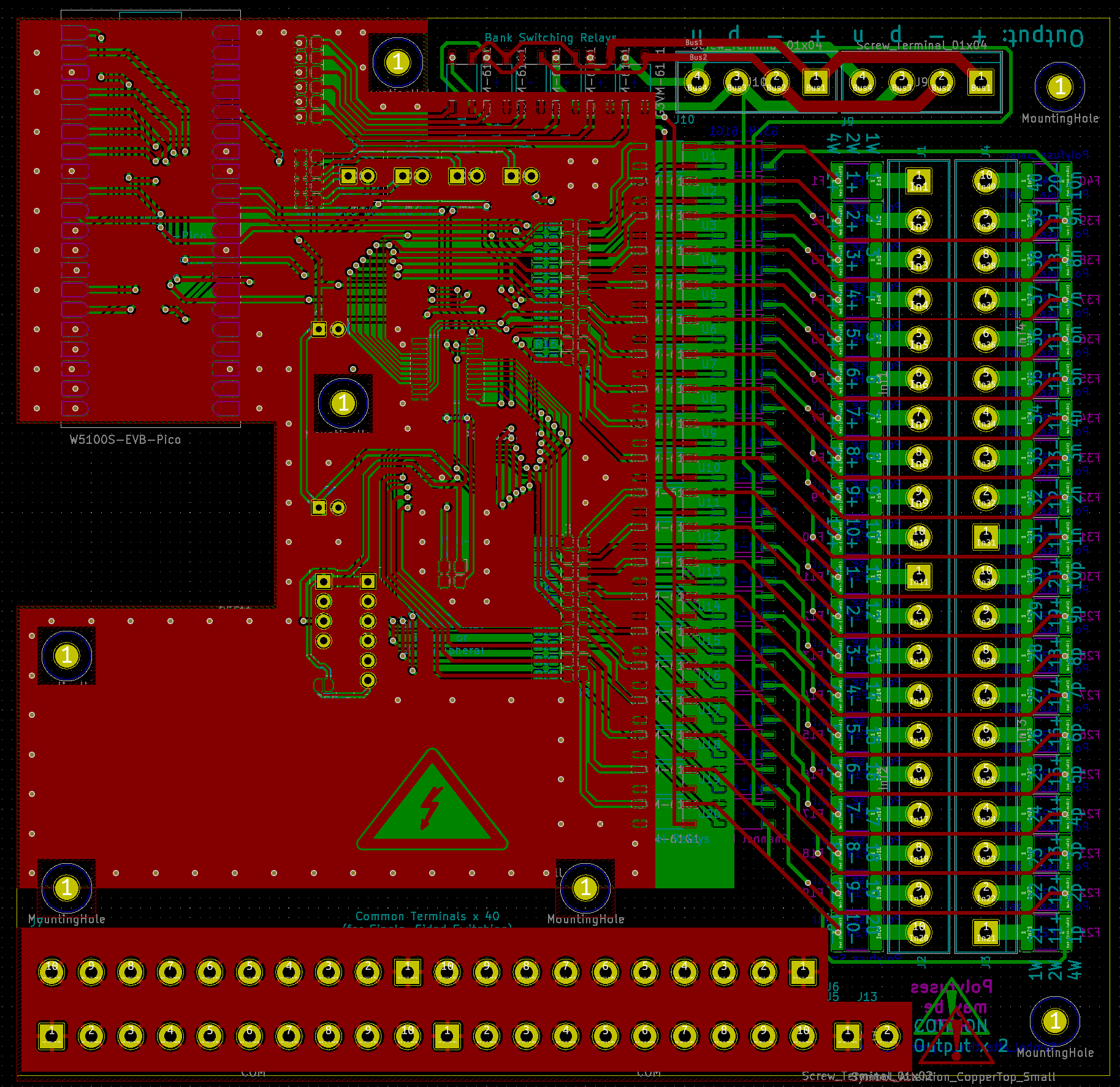
I designed the PCB in KiCad 5 – I still haven’t made the jump to KiCad 6. It’s not the most glamorous design and was a product of a bit of a rush in my spare time. The board was designed so components would be populated both sides to minimise board area to minimise PCB cost. Unfortunately, this makes it a bit more of a challenge to build, but I felt like some careful design could make it possible to construct at home. Some of the considerations include not having components that needed to be soldered directly opposite – this would avoid potentially desoldering components on the opposite side.
I’m no PCB design expert, so the design itself will probably look ugly to some, but it was designed to avoid thin traces where possible (for manufacturability), to have no flood fill for regions where input is being handled, but rely on the fill to carry ground on both sides. The 3V3 power is carried as routed traces instead. Due to the size of the board, some traces are a bit crammed, but sufficient isolation should still exist.


It would also be my first design making use of mostly SMD components, with the exception of the castellated W5100S-EVB-PICO, pin-headers, terminal blocks, capacitors and LEDs. The design also features a “cutout” in the board – this is because the ethernet port is a through-hole component, and thus cannot sit flat on the board. As I didn’t really want to create a Raspberry Pi Pico footprint with holes and use headers to mount it, I decided to make a cutout for it despite this meaning the Ethernet port would not have much mechanical support.
This is actually the second design of the board, as the first design was made for the PCA9535DWR (ignore the silkscreen) which has a more hand-solderable 1.25mm pin pitch. Unfortunately, when I came to order parts, the chip had gone out of stock leading the PCA9535DBR with a 0.65mm pitch instead! Having already sent the board for design, I quickly deleted the footprint, substituted a new one and hooked the traces back together. Unfortunately, I had already sent the first design off to manufacture, so I ended up with five boards I wouldn’t use …
The PCB gerbers can be downloaded here – ssmatrixv1.zip for the PCA9535DWR and the ssmatrixv1.1 for the PCA9535DBR. Ignore the silkscreen as it is not correct on the V1 file! The V1.1 design also features some ground net stitching just for kicks … I ususally forget that.

I decided to do a quick computation of cost to see just how much a single built unit would cost in parts. The bottom line of AU$173.45 including GST is quite affordable, but makes this the most expensive project of my own design I had attempted.
But everyone knows this is not the real cost – because of the way price breaks and minimum order quantities work, but also because I have a tendency to order spares in case things break. Another is merely the fact I got the PCB design made for an I/O expander I couldn’t buy …
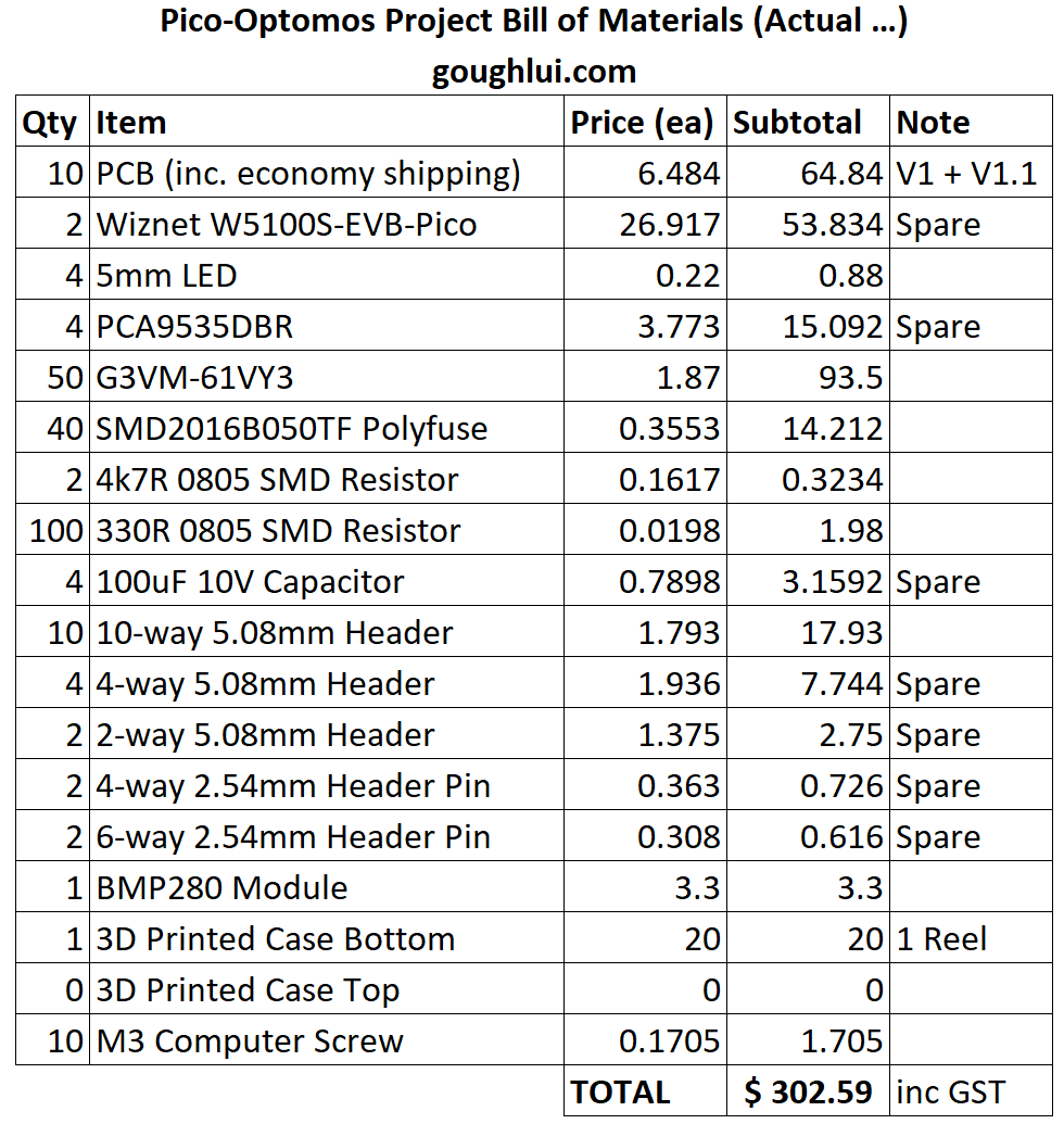
… which meant the actual cost was more like AU$302.59. This was still quite affordable, considering it is something I couldn’t just “buy”. If we add in the three hours of construction, one hour of 3D modelling and an hour-and-a-half of programming time, I’d be running about AU$600 which makes it seem less of a bargain, but it’s still educational!
JLCPCB Purple – Any Good?
I often get offers from PCB manufacturers offering to do sponsored PCB builds for review, but they never come at a good time for me, so I have only very rarely ever taken them up. In fact, I usually just find it easier to pay the economical prices at JLCPCB and this time is no exception – no sponsorship here!
Part of my interest was because JLCPCB seems to have recently begun offering purple solder-resist as an option. Previous orders had me preferring the matte-black process at JLC as being the best, so how will the purple process compare?

The two board variants came back in purple as expected. Using the economical HASL finish, it doesn’t have the purple-and-gold aesthetic that ENIG/ENEPIG boards have, but it is also a lot cheaper. In the end, including the most economic shipping option, each board cost just AU$6.48.

Both boards seemed to have equivalent quality that they may just have been panelised onto the same run. We have to look closer to see what the manufacturing quality is like.

The 0.65mm pitch pins seem well resolved, but the soldermask on this side seems offset with pads pushing towards the top left. This is well within acceptable limits.

This is perhaps more easily seen on the OptoMOS relay pads.

Just as with JLCPCB’s other processes, the silkscreen often features “jaggies” as if it’s not necessarily perfectly aligned in the X/Y direction, but it is at least bold and well-defined.

The alignment on the rear side of the board seems better. Via tenting seems to be a bit inconsistent, but this is normal for LPI-based processes.

Looking closer at the V1.0 board’s underside, the alignment seems very good.

The top side shows a very similar offset, suggesting to me that both were made on the same panel. Overall, I’d say the purple process seems fine although I think I still like the matte black option the best. Something about the consistency (or perhaps my good luck) has my matte black boards having consistently good aignments and sharp silkscreens. No complaints though – especially for the low price!
Hand-Construction
Having come around on SMD construction after doing a number of practice kits, it was now time to construct my double-sided behemoth. Hopefully all goes well!


I worked only with a hot air gun, soldering iron, flux pen and regular solder wire. No stencils, no solder paste – they were just too fiddly for my liking. I worked by pre-tinning pads, fluxing them up, placing components and hot-airing them on. The dispensing was not so accurate, but still, seems good enough.
Construction was done in an unusual order to try and minimise risk. I started with the polyfuses, then resistors, then I/O expanders, then channel relays. Larger components and through-holes then came next, with the environmental sensor and W5100S-EVB-Pico coming last.

While I didn’t get everything perfect, I think I did a pretty good job overall. I did cheat a little, using 60/40 leaded solder, but no exotic low-temperature stuff here. The components didn’t always “pull” to a nice straight line – this was probably because of uneven solder dispensing, but it shouldn’t be a functional issue.
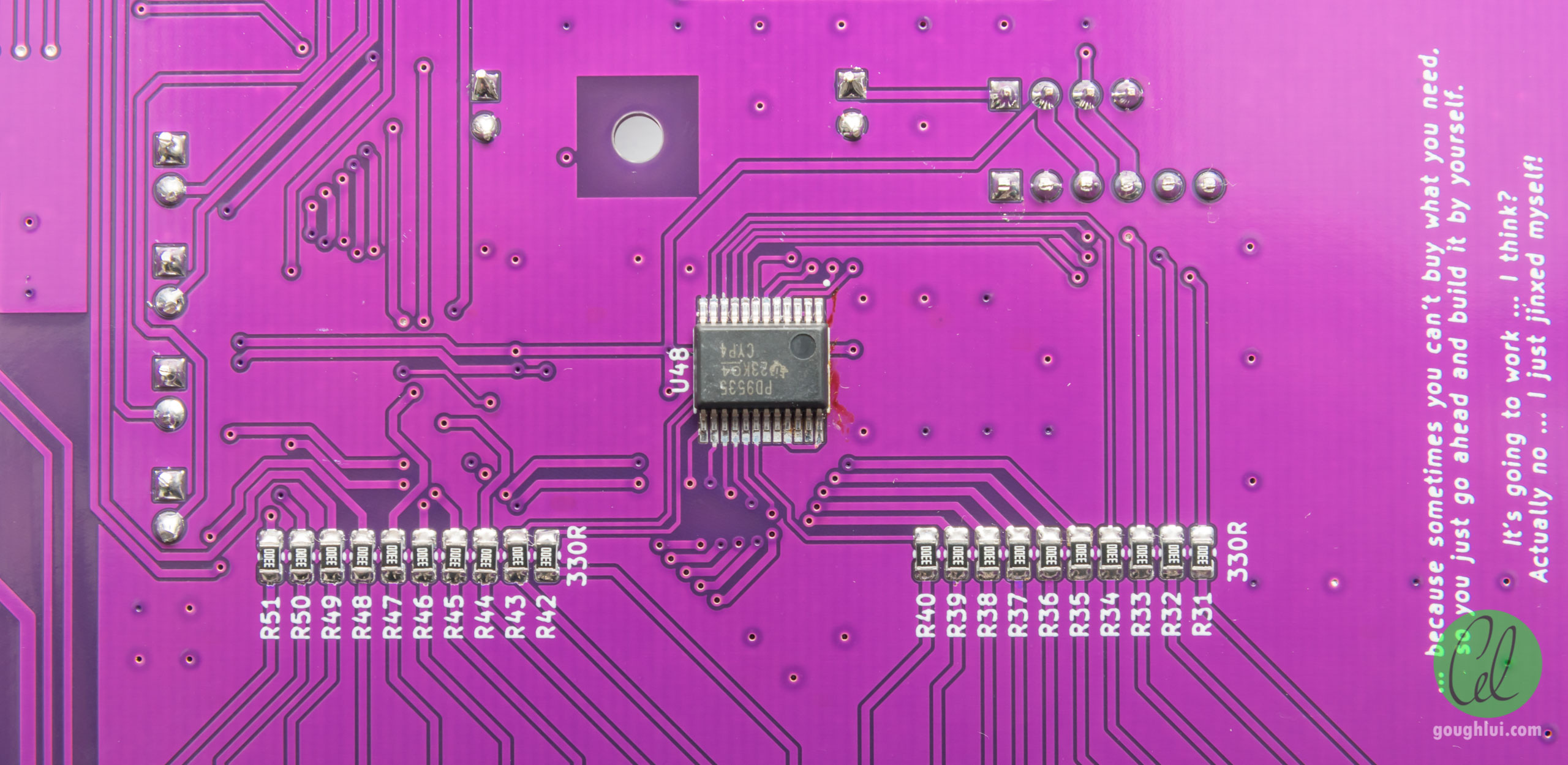
The I/O expander on the rear managed to get mounted into place just fine – the pitch had me a little concerned. The solder is perhaps a little on the low-side, but still probably enough.

The I/O expander on the top side had enough solder, but was mounted at a small angle. No big deal, I’d say. The top side is arranged similarly to the back with channel relays mounted in a “barrier” line and drive resistors being clustered in groups for routing efficiency. The routing was slightly challenging given the small pitch of the I/O expander and the two-layer nature of the board, but I managed with a few more vias than normal. The bank-switching relays are along the top edge, with the dropping resistors mounted close to those for the LEDs. The BMP280 environmental sensor module was mounted directly by soldering header pins down. It is noted that the module has its own pull-ups which are in parallel with the ones on the board (5k1 instead of 4k7 due to what I had on hand), but the equivalent value is still within tolerance, so they were not removed.

The W5100S-EVB-Pico did fit in the cutout that I provided and the castellated edges seemed to make for a solid fit. The Ethernet port, however, is a little difficult to access to release the tab, and the thinner PCB substrate of the Pico also means the stress may bend the board if the user is not careful. This was not an ideal solution, but it was a compromise since I was intending both USB and Ethernet interfaces to be accessible which is difficult without having to make the board larger.

The terminal blocks from CUI Devices are much nicer than the generic terminal blocks, but they are made of blocks of two or three interlinked together. Nevertheless, the silkscreen clearly labels each channel, as intended.

It was only at the end that I noticed that I didn’t have a two-pole terminal block of the same type used throughout the board. As a result, I ended up with a larger one for the common terminals. This is an unfortunate mismatch, but functionally, it shouldn’t really matter. Oh well.
Putting it in a Box
A bare board isn’t very safe or durable, so I decided to build it a case.

Not being proficient at any big CAD package, and not having one installed, I went back to Tinkercad to build this design. There are a few stepped square standoffs where M3 screws will bite directly into plastic to secure the board. Other squares are placed to support the board from behind where no chips are likely to be mounted. Support brace bars are placed in the middle of the terminal block row as well, to resist the downward force from when the terminal blocks are screwed down. Quite a bit of clearance is provided on the rear to allow through-holes, polyfuses and relay packages to have ample clearance.


Printing with a brim to prevent the edge from warping upwards on my uneven print bed, the print came out perfectly and the board mounted without any fuss with spare M3 computer screws.

I also designed a rather loose cover to go over the top. Some clearance is provided from the edge for the USB port to avoid damage, otherwise the lid is supported around the edges with about 1mm clearance in both axes in case of print scaling anomalies. The case height is deliberately tall, to accomodate the Ethernet port.
The .stl files generated to print the box can be downloaded here. A redesign could be worthwhile to tighten it up, or to provide notches for USB-micro-B cables to fit better, especially when the bottom is stacked into an upturned lid.
Coding the Software
The software itself was a rush job, borrowing the code from the earlier car fridge and relay mux. The code was modified to be a bit more SCPI-compliant, offering an *OPC? command and also not responding with “\n” after every non-query command. The porting process to the RP2040-based board was relatively painless, although a few things had to be observed:
- The Arduino Pico core has to be installed to support the board.
- A different Ethernet library was installed to support the board on the advice of this instructable.
- The Adafruit BMP280 library was cloned and modified to replace Wire function calls with Wire1, as the second I2C controller was used in this design. Unfortunately, it seems not all libraries are written to accept multiple controllers, hence this is a workaround. The PCA95x5 library is, so therefore this workaround isn’t needed.
- The onboard LED is connected to GPIO 25.
- Output can have drive strength configured (2, 4, 8, 12mA) which is probably necessary to avoid unexpected voltage drops when driving loads directly.
- Rebooting the RP2040 requires a call to rp2040.reboot().
- The EEPROM functionality is emulated in flash, requiring a call to EEPROM.commit() to cause the write to occur. A call to EEPROM.begin() also requires the size to be passed as an argument.
Aside from this and a few scary compiler warnings in red due to redefinitions between the Arduino Pico core and Ethernet Library, the porting was relatively straightforward. From there, it was all about extending functionality to drive the relay matrix as required for each mode.
To do this, I decided that a MOD y command is needed to choose the mode, with SEL xx choosing a channel (e.g. MOD 1, SEL 5 = 1-wire mode, select input 5). But then, I thought it would be even better to use three digit channel numbers where the first digit indicates mode and the latter two digits indicate channel number – e.g. SEL 105 will choose 1-wire mode, input 5 and SEL 410 will choose 4-wire mode, input 10. A SEL 0 is equivalent to SEL 100 or SEL 200 or SEL 400 and will unselect the output (i.e. all disconnected). The onboard LED is used to visualise the selection status. The board boots default in Mode 0 where any selection will create an error condition to avoid accidental misconnection in case of a power interruption or board reboot.
The code has also been extended to implement an error queue using SYST:ERR? thus allowing for incorrect commands and internal hardware errors to be discovered and recorded. A key fear of mine is a communication error with I2C, thus all writes to the I/O expanders are verified with a read straight after. Any miscompares will result in an internal error being logged. Another fear is incorrect execution (e.g. due to power glitch or cosmic-ray upset) which could lead to code being run when it shouldn’t. As a result, most “if” cases are explicitly stated with the “else” catch-all not supposed to be executed under any condition. If those are ever executed, an internal error will be logged. It’s not possible to catch every sort of mistake, but at least this should give me some hints when things do go wrong. On the other hand, the compiler may just end up optimising it out …
One way around this may be to retry operations in case of a detected error, only logging an error after a certain number of retries are exhausted. But I feel this may not be necessary – my I2C bus isn’t exactly pushing high-speed, so should be pretty reliable.
The code is provided in the Appendix section which follows this post (at the bottom of the full view of this post).
Testing
The first thing I did was to build the project progressively, testing as I went. This involved checking LEDs were working, port expanders were working, Ethernet was working and environmental sensor is working. Only then did I start loading the big chunk of code and begin getting the matrix logic coded up.
I went through each of the outputs in one-wire mode to catch any non-functional or cross-connected channels and did not identify any. Then, in two-wire mode, I hand probed a selection of settings and the same in four-wire mode. I’m fairly confident the logic should be correct, but there are no guarantees, so use the project at your own risk! The polyfuses should hopefully avoid catastrophe.
At this time, the reliability of the software was to be tested. In order to do this, I wrote a short Python script (also available in the Appendix) which issues channel selection commands at random (three-digit channels, all valid combinations) followed by an operation complete query as quickly as possible. Every 1000 selections, it will print a line of the total number of commands, the current time, the error queue and the measurements from the environmental sensor.

When running, the mode LEDs flicker very quickly, indicating the system performs quite well, even with the 1ms relay off dead-time and 3ms relay on delay. Leaving the system to run overnight, it did not fail …

… with zero error code reported every time in over 5.25-million selection operations. The average time per SEL x + *OPC? loop is around 8.9ms (equating to 112 channels/sec) over LAN SOCKET connection. Tested performance over USB-CDC was practically identical which is faster than I had expected (based on my AVR-based experience)!
The speed is perhaps not my main interest as I do not usually synchronise my instruments well enough to take advantage of it, and because I’m rarely interested in sub-1PLC measurements anyway. With auto-ranging, most DMMs can’t even reach 50 readings per second in a 50Hz country, so this is plenty fast enough. But it does make me regret not breaking out that LED GPIO connection to a BNC connection, in case it can be used to drive the Trigger In on a DMM to more speedily initiate a measurement compared to a bus-based *TRG.
Conclusion
In the end, it seems to be a happy ending to a rather big homebrew project (for me) – aside from the parts shortage that necessitated a last-minute respin of the PCB, the design actually worked as intended and every I/O pin was used. The hand-soldering, while imperfect, was still sufficient that everything worked first time. The 3D printer definitely played its part, building a rudimentary case which keeps it safe. The solution is rather compact, although perhaps not 100% as performant as commercial scanning DMM solutions. That’s fine though – as it’s better than nothing and speed rarely is without tradeoffs (e.g. measurement < 1PLC causes mains-borne noise).
Manual probing and stress testing of the interface seems to show that the unit is stable, although the code is pretty hacky and features magic numbers throughout. Not my proudest effort, inheriting many bits from the older car fridge and relay muxes, but it was surprisingly easy to port to the RP2040. The performance and memory capacity of the RP2040 really leaves the 8-bit AVR-based Arduinos in the dust – no surprises there. What is a surprise is the affordable price and convenient form factor. I think I’ll be using more RP2040 going forward.
Now that it’s done … I have four spare PCBs for the PCA9535DBR and five that accomodate the PCA9535DWR. Will I build more multiplexers? Probably not … one should be enough. While I could probably post it out to those who are interested to build their own, the cost of postage may outweigh the cost of getting another batch manufactured and send directly to you …
From here, it’s probably going to be incremental improvements with code – changing to 400kHz I2C seems to have cut channel selection time to 6.75ms for a channel scan rate of about 148 ch/s with no noticeable reliability impact. That’s fascinating, given 4ms of that is in enforced delays in the code to account for relay response time (could be trimmed to 3.5ms)! Overclocking the RP2040 is a possibility as well, not that we really need that … Perhaps reliability and safety can be improved by retrying if a mismatch occurs, rather than logging an error and continuing, while Ethernet retries and timeout could be increased to handle transient network faults. Using gpio_put_masked instead of looping to set the GPIOs would save a bit of time as well.
Update: I made the changes to my local copy of the code (not the one below), compiled with -OFast and managed to end up with about 5.934ms selection time for a scan rate of 168 ch/s now! Overclocking to 250MHz cut this down to 5.371ms or 186ch/s, but the difference is perhaps not worth the reliability risk.
If you have time, why not check out my blog series for the element14 Experimenting with Thermistors Design Challenge –
- Blog #1: Characterising Thermistors – Introduction
- Blog #2: Characterising Thermistors – What’s In The Box?
- Blog #3: Characterising Thermistors – A Quick Primer, Beta Value & Steinhart-Hart Coefficients
- Blog #4: Characterising Thermistors – An Inconvenient Truth, Taking Things to the Fifth Degree
- Blog #5: Characterising Thermistors – Measuring Resistance Is Not So Easy!
- Blog #6: Characterising Thermistors – Is Self-Heating a Problem or Not?
- Blog #7: Characterising Thermistors – Boiling, Freezing and Zapping the Truth Out of Them!
- Blog #8: Characterising Thermistors – Practically Running Multiple Thermistors
- Blog #9: Characterising Thermistors – Multi-T Results, Insulation R Redux, 5th Order Fits & Model Performance
- Blog #10: Characterising Thermistors – Multiple Thermistors on ESP8266
- Blog #11: Characterising Thermistors – Show Me Your Curves
- Blog #12: Characterising Thermistors – Sticking Rings on Tabs & Sinks, Absolutely Crushing It!
- Blog #13: Characterising Thermistors – Pulling Out, Overload, Response Time, Building a Flow Meter & Final Conclusion
Appendix: Arduino Controller & Python Stress Test Code
In the spirit of “giving away” the project in case it is useful to anyone else, I’ve made the code available for download as a ZIP file or viewing in the listings below. The code itself is not something I’m particularly proud of – it’s more of a “quick hack” to make things work, as I managed to cook it up in about an hour and a half. As a result, it has magic numbers all over the place. “Do as I say, not as I do,” as they say …
The Arduino code that is used to drive the PCB is reproduced below:
// goughlui.com 40-Input Solid State Relay Multiplexer
// with Raspberry Pi RP2040-based Wiznet W5100S-EVB-Pico
// Code v1.0.3 - September 2022 - Use at your own risk.

// Relies on:
// https://github.com/earlephilhower/arduino-pico (RP2040)
// https://github.com/WIZnet-ArduinoEthernet/Ethernet (W5100S)
// https://github.com/hideakitai/PCA95x5 (PCA9535)
// https://github.com/adafruit/Adafruit_BMP280_Library (BMP280)
// N.B. Modified replacing Wire with Wire1, Renamed "_W1" suffix.

// Pin allocations matching PCB of my own design, updated to behave
// more like ordinary SCPI devices do but does not support different
// variations of the same command or command chaining.
// Code inherits most of its base from car fridge / relay mux projects.
// Supports TCP Socket and USB-CDC interfaces, DHCP optional.

// Uses 75720 bytes (3%) storage, 9360 bytes (3%) dynamic memory
// USB = 8.9ms/selection, LAN SOCKET = 7.98ms/selection
// Based on SEL xxx + *OPC?

// Pin Allocations
// ioex1 - U1 to U16
// ioex2 - U17 to U32
// GO0-GP7 - U33 to U40
// GP8 - U41 (BT11)
// GP9 - U42 (BT21)
// GP10 - U43 (BT31)
// GP11 - U44 (BT41)
// GP12 - U45 (BT22)
// GP13 - U46 (BT42)

#include <Wire.h>
#include <PCA95x5.h>
#include <Ethernet.h>
#include <EEPROM.h>
#include <Adafruit_BMP280_W1.h>

#define M1_LED 14
#define M2_LED 15
#define M4_LED 28
#define FLT_LED 22
#define SEL_LED 25

#define MAX_CMD_LEN 256 // Sufficient for needs, RAM needs to be considered.
#define MAGIC_VALUE 28 // Preset magic value. Change to invalidate existing settings.

unsigned long ltime;

PCA9555 ioex1;
PCA9555 ioex2;

Adafruit_BMP280_W1 bmp; // I2C
int bmpavail=0;

// Ethernet Server Variables
byte mac[6] = {0x00, 0xAA, 0xBB, 0x00, 0x00, 0x00}; // Set MAC
byte ipaddr[4]= {192, 168, 0, 2}; // Set Static IP
IPAddress ip();
EthernetServer server(5025);
bool dhcpflag = 0; // Set DHCP mode
char ibuf[MAX_CMD_LEN] = {'\0'};
byte iptr=0;
char respbuf[MAX_CMD_LEN] = {'\0'};
bool serbyte=0;
bool newbyte=0;

// Relay Variables
int relayval = 0;
int muxmode = 0;
int reqchan = 0;
int modenumber;

// Progmem Data
const char helpdata[] PROGMEM = {"Command List: *IDN? *RST? SEL [0-40,100-140,200-220,400-410] SEL? MOD [1,2,4] MEAS:TEMP? MEAS:BARO? SYST:ERR? *OPC? STOP IP MAC DHCP NVERASE REBOOT"};
const char deviceID[] PROGMEM = {"goughlui.com Solid-State Relay Mux,V1.0.3,0001"};

// Error Log
int errorlog[20];

void resetBoard () {
  rp2040.reboot();
}

void setup() {
  Ethernet.init(17); // CS pin for W5100S-EVB-Pico
  int magic;
  EEPROM.begin(512); // Emulated EEPROM
  Wire1.begin(); // Using I2C Bus 1
  Serial.begin(115200); // Do not block so can boot w/o USB!

  ioex1.attach(Wire1,0x20);
  ioex1.polarity(PCA95x5::Polarity::ORIGINAL_ALL);
  ioex1.direction(PCA95x5::Direction::OUT_ALL);
  ioex1.write(PCA95x5::Level::L_ALL);

  ioex2.attach(Wire1,0x21);
  ioex2.polarity(PCA95x5::Polarity::ORIGINAL_ALL);
  ioex2.direction(PCA95x5::Direction::OUT_ALL);
  ioex2.write(PCA95x5::Level::L_ALL);

  bmpavail = bmp.begin();

  // Setup All Pico Pins
  for (int pin=0;pin<14;pin++) {
    pinMode(pin,OUTPUT_12MA); // Max drive for SSRelays
    digitalWrite(pin,LOW);
  }
  pinMode(M1_LED,OUTPUT); // Lower Drive for LEDs
  pinMode(M2_LED,OUTPUT);
  pinMode(M4_LED,OUTPUT);
  pinMode(FLT_LED,OUTPUT);
  pinMode(SEL_LED,OUTPUT);

  // LED Test
  digitalWrite(M1_LED,HIGH);
  digitalWrite(M2_LED,HIGH);
  digitalWrite(M4_LED,HIGH);
  digitalWrite(FLT_LED,HIGH);
  digitalWrite(SEL_LED,HIGH);
  delay(500); // All LEDs on for 0.5s

  // Set all LEDs off
  digitalWrite(M1_LED,LOW);
  digitalWrite(M2_LED,LOW);
  digitalWrite(M4_LED,LOW);
  digitalWrite(FLT_LED,LOW);
  digitalWrite(SEL_LED,LOW);

  alloff(); // All relays off, ready to run.

  for (int z=0;z<20;z++) { // Initialise Error Log
    errorlog[z]=0;
  }

  EEPROM.get(500,magic);
  if (magic == MAGIC_VALUE) { // Magic value passes, EEPROM contents valid
    EEPROM.get(0,mac);
    EEPROM.get(10,ipaddr);
    EEPROM.get(20,dhcpflag);
  } else { // Magic value fails, thus restore defaults*/
    EEPROM.put(0,mac);
    EEPROM.put(10,ipaddr);
    EEPROM.put(20,dhcpflag);
    magic = MAGIC_VALUE;
    EEPROM.put(500,magic); // Write Magic value
    EEPROM.commit();
    delay(100);
    resetBoard(); // Reset board to apply values
  }
  if(dhcpflag) {
    ltime=millis();
    while (!Ethernet.begin(mac) && (ltime + 60000 < millis())) {
      // Couldn't get an address, let's wait up to 60s for an address.
      // Unsure how robust DHCP mode is - suggest avoiding.
    }
  } else {
    IPAddress ip(ipaddr[0],ipaddr[1],ipaddr[2],ipaddr[3]);
    Ethernet.begin(mac, ip);
  }
  server.begin();
  if(!bmpavail) {
    pusherror(100); // No temperature sensor
  }
}

void loop() {
  EthernetClient client = server.available();
  char c;
  if (client) {
    if (client.connected() && client.available()) {
      c = toupper(client.read());
      serbyte = 0;
      newbyte = 1;
    }
  }
  if (Serial.available()) {
    c = toupper(Serial.read());
    serbyte = 1;
    newbyte = 1;
  }
  if(newbyte) {
    newbyte = 0;
    if (c != '\r') { // eat any carriage returns for compat with \r\n
      if (c == '\n') {
        ibuf[iptr]='\0';
        proccmd();
        if(serbyte) {
          if(strlen(respbuf)) {
            Serial.print(respbuf);
            Serial.write("\n"); // Only send newline if there is a reply!
          }
        } else {
          if(strlen(respbuf)) {
            client.print(respbuf);
            client.write("\n"); // Only send newline if there is a reply!
          }
        }
        iptr=0;
      } else {
        if (iptr<MAX_CMD_LEN) {
          ibuf[iptr]=c;
          iptr++;
        }
      }
    }
  }
  // DHCP Maintain
  if (dhcpflag) {
    Ethernet.maintain();
  }
}

// Command Processing Function
void proccmd() {
  respbuf[0]='\0';
  if(ibuf[strlen(ibuf)-1]=='?') { // IS A QUERY STRING
    if (!strcmp("*IDN?",ibuf)) {
      for (int n=0; n<strlen_P(deviceID); n++) {
        respbuf[n]=pgm_read_byte_near(deviceID+n);
      }
      respbuf[strlen_P(deviceID)]='\0';
    } else if (!strcmp("*RST?",ibuf)) {
      alloff();
      muxmode=0;
      setmode();
    } else if (!strcmp("SEL?",ibuf)) {
      sprintf(respbuf,"%d",relayval);
    } else if (!strcmp("MOD?",ibuf)) {
      sprintf(respbuf,"%d",muxmode);
    } else if (!strcmp("*OPC?",ibuf)) {
      sprintf(respbuf,"1");
    } else if (!strcmp("HELP?",ibuf)) {
      for (int n=0; n<strlen_P(helpdata); n++) {
        respbuf[n]=pgm_read_byte_near(helpdata+n);
      }
      respbuf[strlen_P(helpdata)]='\0';
    } else if (!strcmp("IP?",ibuf)) {
      sprintf(respbuf,"%d.%d.%d.%d",Ethernet.localIP()[0],Ethernet.localIP()[1],Ethernet.localIP()[2],Ethernet.localIP()[3]);
    } else if (!strcmp("MAC?",ibuf)) {
      sprintf(respbuf,"%02X:%02X:%02X:%02X:%02X:%02X",mac[0],mac[1],mac[2],mac[3],mac[4],mac[5]);
    } else if (!strcmp("MEAS:TEMP?",ibuf)) {
      if(bmpavail) {
        sprintf(respbuf,"%f",bmp.readTemperature());
      } else {
        sprintf(respbuf,"0");
      }
    } else if (!strcmp("MEAS:BARO?",ibuf)) {
      if(bmpavail) {
        sprintf(respbuf,"%f",bmp.readPressure()/100.0);
      } else {
        sprintf(respbuf,"0");
      }
    } else if (!strcmp("SYST:ERR?",ibuf)) {
      int lerror = poperror();
      if (lerror==0) {
        sprintf(respbuf,"0,No Error");
      } else if (lerror==100) {
        sprintf(respbuf,"100,No Temperature Sensor");
      } else if (lerror==200) {
        sprintf(respbuf,"200,Select with No Mode");
      } else if (lerror==201) {
        sprintf(respbuf,"201,Invalid Mode Number");
      } else if (lerror==300) {
        sprintf(respbuf,"300,Invalid Query");
      } else if (lerror==301) {
        sprintf(respbuf,"301,Invalid Command");
      } else if (lerror==999) {
        sprintf(respbuf,"999,Error Queue Overflowed");
      } else {
        sprintf(respbuf,"%d,Internal Error",lerror);
      }
    } else {
      pusherror(300); // Invalid Query
    }
  } else {
    if (!strncmp("SEL ",ibuf,4)) {
      // Read in settings using sscanf
      sscanf(ibuf+4,"%d",&relayval);
      if((relayval>=0 && relayval<=40 && muxmode == 1)||(relayval>=0 && relayval<=20 && muxmode == 2)||
         (relayval>=0 && relayval<=10 && muxmode == 4)||(relayval>=100 && relayval<=140)||
         (relayval>=200 && relayval<=220)||(relayval>=400 && relayval<=410)) {
        setchan();
      } else if (muxmode == 0) {
        pusherror(200); // Selection without mode
      }
    } else if (!strncmp("MOD ",ibuf,4)) {
      // Read in settings using sscanf
      sscanf(ibuf+4,"%d",&modenumber);
      if(modenumber == 0 || modenumber == 1 || modenumber == 2 || modenumber == 4) {
        muxmode=modenumber;
        setmode();
      } else {
        pusherror(201); // Invalid Mode Selection
      }
    } else if (!strcmp("STOP",ibuf)) {
      alloff();
      relayval=0;
    } else if (!strncmp("IP ",ibuf,3)) {
      sscanf(ibuf+3,"%d%d%d%d",&ipaddr[0],&ipaddr[1],&ipaddr[2],&ipaddr[3]);
      EEPROM.put(10,ipaddr);
      EEPROM.put(20,bool(0));
      resetBoard();
    } else if (!strncmp("MAC ",ibuf,4)) {
      sscanf(ibuf+4,"%x%x%x%x%x%x",&mac[0],&mac[1],&mac[2],&mac[3],&mac[4],&mac[5]);
      EEPROM.put(0,mac);
      resetBoard();
    } else if (!strcmp("DHCP",ibuf)) {
      EEPROM.put(20,bool(1));
      resetBoard();
    } else if (!strcmp("NVERASE",ibuf)) {
      EEPROM.put(500,int(0)); // Erases the magic value causing EEPROM to be reinitialised
      resetBoard();
    } else if (!strcmp("REBOOT",ibuf)) {
      resetBoard();
    } else {
      pusherror(301); // Invalid Command
    }
  }
}

// Turn All Relays Off
void alloff () {
  for (int pin=0;pin<14;pin++) {
    digitalWrite(pin,LOW);
  }
  ioex1.write(PCA95x5::Level::L_ALL);
  if(ioex1.read() != 0) {
    pusherror(501); // ioex1 readback mismatch
  }
  ioex2.write(PCA95x5::Level::L_ALL);
  if(ioex2.read() != 0) {
    pusherror(502); // ioex2 readback mismatch
  }
  delay(1); // Relay Off Time
  digitalWrite(SEL_LED,LOW);
}

// Set Mode Indicators
void setmode() {
  if (muxmode == 1) {
    digitalWrite(M1_LED,HIGH);
    digitalWrite(M2_LED,LOW);
    digitalWrite(M4_LED,LOW);
  } else if (muxmode == 2) {
    digitalWrite(M1_LED,LOW);
    digitalWrite(M2_LED,HIGH);
    digitalWrite(M4_LED,LOW);
  } else if (muxmode == 4) {
    digitalWrite(M1_LED,LOW);
    digitalWrite(M2_LED,LOW);
    digitalWrite(M4_LED,HIGH);
  } else {
    digitalWrite(M1_LED,LOW);
    digitalWrite(M2_LED,LOW);
    digitalWrite(M4_LED,LOW);
  }
}

// Choose a Channel using global relayval, muxmode
void setchan() {
  alloff();
  if (relayval >= 100) {
    muxmode=relayval/100;
    reqchan = relayval;
    setmode();
  } else {
    reqchan = muxmode*100 + relayval;
  }
  if(reqchan % 100 != 0) { // If not a "unselect" (i.e. 0, 100, 200, 400)
    if (reqchan>100 && reqchan <=140) {
      if (reqchan-101 < 16) { // Channel Relay
        ioex1.write(1<<(reqchan-101));
        if (ioex1.read() != (1<<(reqchan-101))) {
          pusherror(503); // ioex1 readback mismatch
        }
      } else if (reqchan-101 < 32) {
        ioex2.write(1<<(reqchan-117));
        if (ioex2.read() != (1<<(reqchan-117))) {
          pusherror(504); // ioex2 readback mismatch
        }
      } else {
        digitalWrite((reqchan-133),HIGH);
      }
      if (reqchan-101 < 10) {
        digitalWrite(8,HIGH);
      } else if (reqchan-101 < 20) {
        digitalWrite(9,HIGH);
      } else if (reqchan-101 < 30) {
        digitalWrite(10,HIGH);
      } else if (reqchan-101 < 40) {
        digitalWrite(11,HIGH);
      } else {
        pusherror(511); // invalid reqchan, but should never happen!
      }
    } else if (reqchan>200 && reqchan <=220) {
      int ry1;
      int ry2;
      if (reqchan-200 <= 10) {
        ry1 = reqchan-201; // 0-9
        ry2 = reqchan-191; // 10-19
      } else if (reqchan - 200 <= 20) {
        ry1 = reqchan-191; // 20-29
        ry2 = reqchan-181; // 30-39
      }
      uint16_t ioex1val = ((1<<ry1)|(1<<ry2));
      uint16_t ioex2val = ((1<<(ry1-16))|(1<<(ry2-16)));
      uint16_t pival = ((1<<(ry1-32))|(1<<(ry2-32)));

      ioex1.write(ioex1val);
      if (ioex1.read() != ioex1val) {
        pusherror(505); // ioex1 readback mismatch
      }
      ioex2.write(ioex2val);
      if (ioex2.read() != ioex2val) {
        pusherror(506); // ioex2 readback mismatch
      }
      for (int c=0;c<8;c++) {
        if(pival & (1<<c)) {
          digitalWrite(c,HIGH);
        }
      }
      if (reqchan-201 < 10) {
        digitalWrite(8,HIGH);
        digitalWrite(12,HIGH);
      } else if (reqchan-201 < 20) {
        digitalWrite(10,HIGH);
        digitalWrite(13,HIGH);
      } else {
        pusherror(510); // invalid reqchan, but should never happen!
      }
    } else if (reqchan>400 && reqchan <=410) {
      int ry1=reqchan-401; // 0-9
      int ry2=reqchan-391; // 10-19
      int ry3=reqchan-381; // 20-29
      int ry4=reqchan-371; // 30-39

      uint16_t ioex1val = ((1<<ry1)|(1<<ry2));
      uint16_t ioex2val = ((1<<(ry2-16))|(1<<(ry3-16))|(1<<(ry4-16)));
      uint16_t pival = (1<<(ry4-32));

      ioex1.write(ioex1val);
      if (ioex1.read() != ioex1val) {
        pusherror(507); // ioex1 readback mismatch
      }
      ioex2.write(ioex2val);
      if (ioex2.read() != ioex2val) {
        pusherror(508); // ioex2 readback mismatch
      }
      for (int c=0;c<8;c++) {
        if(pival & (1<<c)) {
          digitalWrite(c,HIGH);
        }
      }
      digitalWrite(8,HIGH);
      digitalWrite(12,HIGH);
    } else {
      pusherror(509); // invalid reqchan, but should never happen!
    }
    delay(3); // Relay Rise Time
    digitalWrite(SEL_LED,HIGH);
  }
}

// Add an error to the queue
void pusherror(int errc) {
  digitalWrite(FLT_LED,HIGH);
  for (int z=0;z<19;z++) {
    errorlog[z+1]=errorlog[z];
  }
  errorlog[0]=errc;
  if(errorlog[19]!=0) {
    errorlog[19]=999; // Queue overflow
  }
}

// Remove error from queue
int poperror(void) {
  int retval = errorlog[0];
  for (int z=0;z<19;z++) {
    errorlog[z]=errorlog[z+1];
  }
  errorlog[19]=0;
  if(retval==0) {
    digitalWrite(FLT_LED,LOW);
  }
  return(retval);
}
The Python code that performs the stress test is reproduced below:
# Stress Test Program for pico-optomos by goughlui.com
# September 2022 - Use at your own risk!

import pyvisa
import time
import random

resource_manager = pyvisa.ResourceManager()
ins_ssmux =  resource_manager.open_resource("TCPIP0::192.168.xxx.xxx::5025::SOCKET")
#ins_ssmux =  resource_manager.open_resource("ASRLxx::INSTR")
ins_ssmux.read_termination = "\n"

# Roll Call
print("Available:" + "\n" + ins_ssmux.query("*IDN?"))

# Set Up ssmux
print("Setting Up - Solid State Mux")
ins_ssmux.query("*OPC?")

print("Begin Testing")
cmds = 0
f = open("picomuxstress.log",'a')
while True:
  x = random.choice(list(range(100,141))+list(range(200,221))+list(range(400,411)))
  ins_ssmux.write("SEL "+str(x))
  ins_ssmux.query("*OPC?")
  cmds = cmds +1
  if cmds % 1000 == 0 :
    f.write("@Time:"+str(time.time())+" Cmds:"+str(cmds)+" T:" + str(ins_ssmux.query("MEAS:TEMP?"))+ " B:" + str(ins_ssmux.query("MEAS:BARO?"))+" E:"+str(ins_ssmux.query("SYST:ERR?"))+"\n")
    print("@Time:"+str(time.time())+" Cmds:"+str(cmds)+" T:" + str(ins_ssmux.query("MEAS:TEMP?"))+ " B:" + str(ins_ssmux.query("MEAS:BARO?"))+" E:"+str(ins_ssmux.query("SYST:ERR?")))

# Announce Completion
ins_ssmux.close()
print("Script Completed!")