---
title: "Mega Solar Tracker"
url: "https://maker.wiznet.io/scott/projects/mega-solar-tracker/"
markdown_url: "https://maker.wiznet.io/scott/projects/mega-solar-tracker/md"
type: "UCC: User Created Content"
author: "scott"
author_url: "https://maker.wiznet.io/scott/"
original_url: "https://www.hackster.io/team-trouble/mega-solar-tracker-583b47"
published: "2026-07-16"
language: "en"
hardware: ["WIZnet W5500"]
likes: 0
views: 162
comments: 0
source: "WIZnet Makers (https://maker.wiznet.io/)"
---
# Mega Solar Tracker
> Mega Solar Tracker: Beating Clouds with GPS and W5500
Original source: https://www.hackster.io/team-trouble/mega-solar-tracker-583b47
## Components
- **WIZnet W5500** x 1 ([docs](https://docs.wiznet.io/Product/Chip/Ethernet/W5500))
WIZnet parts: W5500 ([Datasheet](https://docs.wiznet.io/Product/Chip/Ethernet/W5500/datasheet?utm_source=maker&utm_medium=project&utm_campaign=w5500), [product hub](https://maker.wiznet.io/products/w5500/))
## Article
## 요약
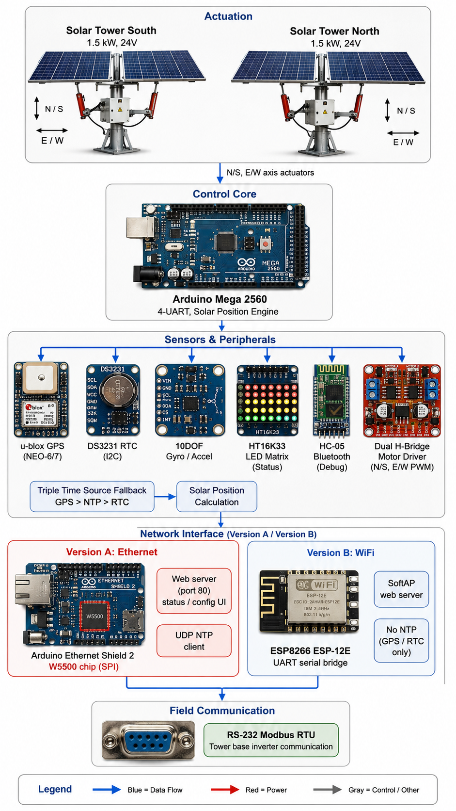
**Mega Solar Tracker**는 기존 광학 센서 기반 태양광 트래커가 부분적으로 흐린 날씨에 **밝은 구름을 태양으로 오인**하는 문제를 GPS·천문 계산 기반 **비광학 추적**으로 해결한 오프그리드 듀얼타워 프로젝트입니다. **Arduino Mega 2560**을 중심으로 GPS/RTC/NTP 3중 시간원을 통합했으며, **WIZnet W5500**(Arduino Ethernet Shield 2)은 상태 모니터링 웹서버와 인터넷 시각 동기화(NTP)를 담당하는 네트워크 게이트웨이로 사용됐습니다.
## 개요
호주 남반구에 설치된 이 트윈타워 태양광 시스템(남/북 타워, 각 1.5kW, 24V)은 원래 광학 센서로 태양 위치를 추적했습니다. 그런데 부분적으로 흐린 날씨에 밝은 구름이 태양보다 더 강한 광원으로 인식되어 **트래커가 구름 쪽으로 잘못 회전**하는 문제가 발생했습니다. 저자(DougalPlummer)는 이를 해결하기 위해 GPS 시각·위치 정보와 천문 계산식으로 태양의 실제 위치를 산출하는 방식으로 컨트롤러를 재설계했습니다.
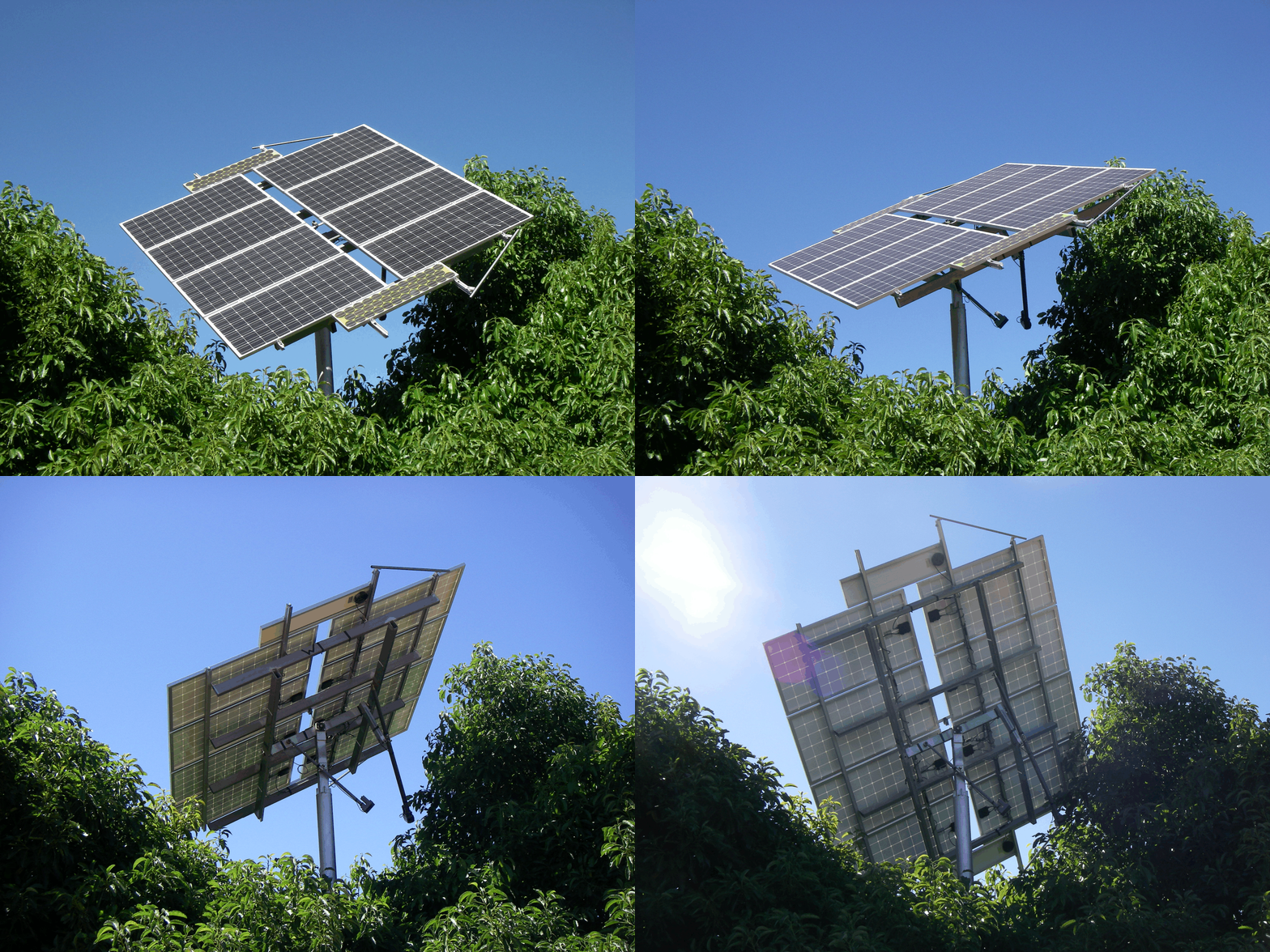
이 프로젝트는 개인 DIY 태양광 발전 설비에 적용된 사례로, **상업적 도입 사례나 특정 법규·정책과 연계된 필요성 근거는 확인되지 않았습니다.** 순수하게 광학 추적의 기술적 한계를 극복하려는 엔지니어링 프로젝트입니다.
## 아키텍처
## 기술 배경
### NTP (Network Time Protocol)
NTP는 UDP 기반으로 서버와 클라이언트 간 시각을 동기화하는 표준 프로토콜입니다. 이 프로젝트는 **GPS → NTP → RTC 순으로 우선순위를 둔 3중 시간원 폴백** 구조를 구현해, 하드웨어 시간원 하나가 빠져도 소프트웨어가 자동으로 대체 소스를 사용하도록 설계했습니다. W5500이 UDP 소켓을 통해 시간 서버(`au.pool.ntp.org`)와 통신하는 역할을 맡습니다.
→ 참고: [NTP RFC 5905](https://datatracker.ietf.org/doc/html/rfc5905)
### Modbus RTU
Modbus RTU는 RS-232/485 시리얼 라인 위에서 동작하는 산업용 요청-응답 프로토콜입니다. 본 프로젝트에서는 트래커 컴퓨터가 **Modbus 슬레이브**로 동작해 타워 베이스의 상위 제어기(또는 인버터)와 각도·상태 레지스터를 주고받습니다. 저자는 표준 라이브러리를 수정해 **레지스터 매핑 커스터마이징**을 지원하도록 했습니다.
→ 참고: [Modbus.org 사양](https://modbus.org/specs.php)
### 하드웨어 TCP/IP 소켓 구조 (W5500)
W5500은 TCP/IP 스택 전체를 칩 내부에서 처리하는 하드와이어드 이더넷 컨트롤러로, MCU는 SPI로 소켓 API만 다루면 됩니다. 이 프로젝트에서 W5500은 센서 데이터를 직접 처리하지 않고 **웹서버 서빙 + NTP 클라이언트라는 순수 네트워크 게이트웨이 역할**만 수행합니다.
→ 참고: [WIZnet W5500 데이터시트](https://docs.wiznet.io/Product/Chip/Ethernet/W5500/W5500-Ethernet-Shield/w5500_ethernet_shield)
## 기술 특징
- **3중 시간원 폴백**: GPS 시각 → 인터넷 NTP → 외부 RTC(DS3231) 순으로 참조, 하드웨어 구성이 바뀌어도 코드 그대로 동작
- **메모리 최적화**: 웹서버 코드 추가 후 SRAM 부족을 겪자 `F()` 매크로로 문자열 상수를 코드 세그먼트에 격리
- **이중 네트워크 버전 실측 비교**: 동일 트래커 로직에 **Ethernet(W5500)**과 **ESP8266 시리얼** 두 버전을 각각 구현해 페이지 생성 속도·전력 소비를 직접 비교
## WIZnet 적용 구조
**실제 사용된 모델**: W5500 (Arduino Ethernet Shield 2 탑재)
- **역할**: 온보드 HTTP 웹서버(포트80)로 트래커 상태·설정 페이지 서빙, UDP 소켓 기반 NTP 클라이언트로 시각 동기화
- **위치**: Arduino Mega의 SPI 버스에 연결, SD카드와 CS핀을 분리해 공유
- **가치 프레이밍**: 이 프로젝트에서 W5500은 센서 데이터를 처리하는 것이 아니라 **네트워크 트래픽만 전담하는 순수 게이트웨이**입니다. 따라서 가치의 핵심은 MCU 부하 경감이 아니라, 저자가 ESP8266 버전과 나란히 구현해 실측 비교한 것처럼 **유선 연결의 예측 가능한 응답성과 전력 특성**입니다.
## WIZnet Makers 유사 사례
- **IoT-based Solar Tracker** (WIZnet 공식): Arduino Mega 2560 + W5100 Ethernet Shield로 이중축 트래커를 웹에 연결한 사례. 본 프로젝트와 동일한 MCU+WIZnet 칩군 조합이나, **DHT22 센서 기반의 표준 IoT 모니터링**에 그쳐 GPS 기반 비광학 추적은 다루지 않습니다.
→ 프로젝트 링크:
- **CLOUD IoT based Single axis Solar Tracker** (taylor): Arduino Mega 2560 + W5100 Ethernet Shield로 Cayenne 클라우드에 연동한 단일축 트래커. 클라우드 대시보드 중심 설계로, 본 프로젝트의 **자체 웹서버 + Modbus 인버터 직접 통신** 방식과 대조됩니다.
→ 프로젝트 링크:
- **IoT-Based Solar Tracker System** (mayuri): Arduino + Ethernet Shield 기반 이중축 트래커이나 **LDR(조도 센서) 광학 추적** 방식입니다. 본 프로젝트가 명시적으로 해결하려는 "구름 오탐" 문제의 대조군에 해당하는 사례입니다.
→ 프로젝트 링크:
세 사례 모두 **Arduino Mega + WIZnet 이더넷 계열 칩**이라는 동일한 네트워크 연결 패턴을 채택했다는 점에서, 이 조합이 메이커 생태계에서 이미 검증된 아키텍처임을 보여줍니다.
| 항목 | 본 프로젝트 | WIZnet IoT Solar Tracker | taylor Cloud Tracker | mayuri IoT Tracker |
| --- | --- | --- | --- | --- |
| 추적 방식 | GPS/천문 계산(비광학) | DHT22+센서(광학 아님) | LDR(광학) | LDR(광학) |
| MCU | Arduino Mega 2560 | Arduino Mega 2560 | Arduino Mega 2560 | Arduino(미상) |
| 네트워크 칩 | W5500 (또는 ESP8266) | W5100 | W5100 | 미상(Ethernet Shield) |
| 통신 방식 | 자체 웹서버+Modbus RTU | 웹서버 | Cayenne 클라우드 | IoT 대시보드 |
| 시간 동기화 | GPS+NTP+RTC 3중화 | 미상 | 미상 | 미상 |
| 축 구성 | 2타워 각 2축(N/S,E/W) | 2축 | 1축 | 2축 |
표에서 보듯 세 사례 모두 **동일 MCU·동일 WIZnet 칩군**을 채택한 반면, 시간 동기화와 추적 알고리즘의 정교함에서는 본 프로젝트가 가장 앞서 있습니다.
## 비즈니스 가치
- **오프그리드 재생에너지 모니터링**: 인터넷 접속이 간헐적인 원격 발전 사이트에서도 GPS/RTC 폴백으로 트래킹이 끊기지 않음
- **소규모 산업 설비의 시간 동기화**: NTP·GPS 3중화 설계는 계측 로그의 타임스탬프 정확도가 중요한 원격 모니터링 장비에 적용 가능
- **인버터·PLC 연계 원격 제어**: Modbus RTU 게이트웨이 구조는 태양광 인버터뿐 아니라 다른 산업 제어기와의 연동에도 확장 가능
- **저비용 이중화 네트워크 설계**: 유선(W5500)/무선(ESP8266) 중 상황에 맞게 선택하는 구조는 설치 환경이 다양한 현장에 참고할 만함
## 한계 및 개선 방향
**현재 한계**
- 전력 소모가 예상보다 높음(저자 실측 총 250mA@12V 중 GPS+WiFi가 약 50% 차지), 오프그리드 배터리(7~9AH) 용량에 부담
- Arduino Mega에서도 웹서버 코드 추가 시 SRAM 부족을 겪음
- Ethernet Shield 2의 RJ45 커넥터 위치가 인클로저 벽면과 간섭
- 블로킹 방식 `loop()` 기반 웹서버로, 동시 다중 요청 처리에는 한계
**개선 방향**
이 프로젝트는 이미 3중 시간원 폴백이라는 견고한 설계를 보여줬습니다. 다만 전력 소모 문제는 **W5500의 저전력 모드(WOL, Power-down)** 활용으로 개선할 여지가 있습니다. 또한 블로킹 웹서버 구조는 W5500의 다중 소켓(최대 8개) 특성을 활용해 비동기 처리로 재구성하면, 저자가 언급한 SRAM 압박도 함께 완화할 수 있습니다.
## FAQ
**Q1. GPS 모듈이 태양광 패널 아래에서도 위성을 수신할 수 있나요?** 저자도 이 부분을 우려해 외부 안테나를 대안으로 고려했다고 언급했습니다. 설치 위치에 따라 GPS 안테나를 패널 외부로 노출하는 것이 안전합니다.
**Q2. Ethernet(W5500)과 WiFi(ESP8266) 중 어느 쪽을 선택해야 하나요?** 저자의 실측에 따르면 두 방식 모두 60mA 내외의 전력을 소비하며 뚜렷한 우위는 없었습니다. **배선이 가능한 환경**이라면 응답 예측성이 높은 W5500 유선 방식이, 배선이 어려운 환경이라면 WiFi가 적합합니다.
**Q3. Modbus RTU 대신 Modbus TCP로 전환할 수 있나요?** W5500이 이미 하드웨어 TCP/IP 스택을 제공하므로, 타워 베이스 통신을 RS-232 대신 W5500의 TCP 소켓으로 전환하면 배선을 단순화할 수 있습니다. 단, 이 경우 라이브러리 재작성이 필요합니다.
**Q4. Arduino Mega 대신 더 작은 MCU로도 구현 가능한가요?** 4개의 UART가 필요한 이유(GPS, 인버터, 블루투스, 진단)를 고려하면 멀티 UART를 지원하는 MCU가 유리합니다. UART가 부족한 MCU라면 소프트웨어 시리얼로 대체해야 하며 타이밍 안정성이 떨어질 수 있습니다.
**Q5. 이 구조를 상업화하려면 BOM 비용에 어떤 영향이 있나요?** GPS 모듈, RTC, 자이로/가속도계, 이더넷 실드가 모두 추가되어 단순 LDR 기반 트래커보다 BOM이 늘어납니다. 다만 오탐으로 인한 트래킹 손실을 줄인다는 점에서 발전량 대비 비용을 함께 고려해야 합니다.
---
## Summary
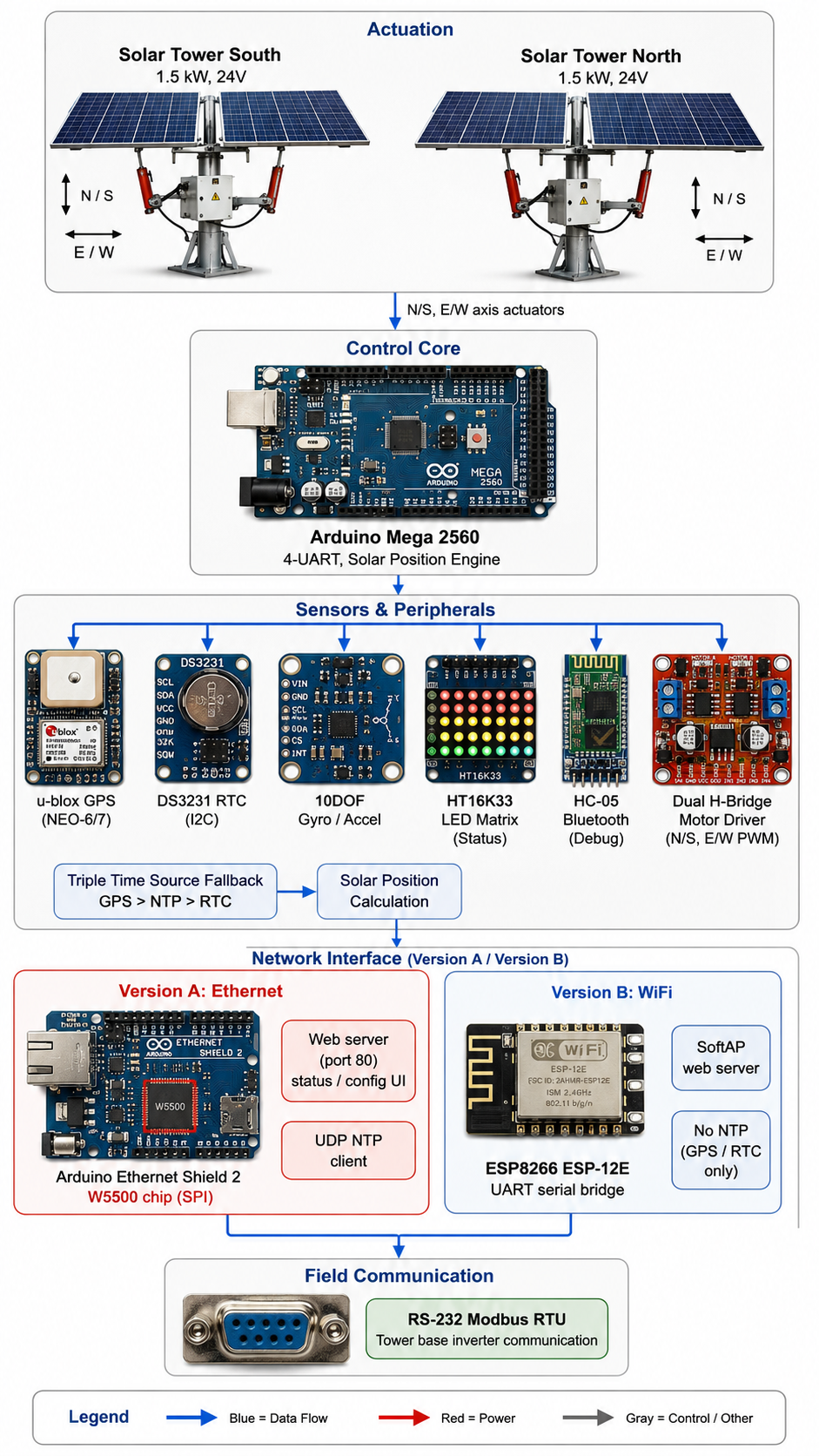
The **Mega Solar Tracker** replaces optical sun-sensing with GPS and astronomical calculations, solving a real problem: optical trackers mistake bright clouds for the sun on partly overcast days. Built around an **Arduino Mega 2560**, the project unifies GPS, RTC, and NTP time sources, while **WIZnet's W5500** (via Arduino Ethernet Shield 2) serves as the network gateway handling status monitoring and internet time sync.
## Overview
This off-grid, dual-tower solar array (south and north towers, 1.5kW each, 24V) originally tracked the sun using optical sensors. The problem: on partly cloudy days, a bright cloud could outshine the actual sun, causing the **tracker to swing toward the cloud instead**. Builder DougalPlummer redesigned the controller to calculate the sun's true position from GPS time and location using astronomical formulas, removing the optical sensor's vulnerability entirely.

This is a personal DIY installation. **No commercial adoption case or regulatory driver was found** for this specific approach — it's a straightforward engineering fix for a well-known limitation of optical tracking.
## Architecture
## Technology Background
### NTP (Network Time Protocol)
NTP synchronizes clocks between servers and clients over UDP. This project builds a **triple-fallback time chain**: GPS first, internet NTP second, and an external RTC as a last resort, so any single time source can be removed without breaking the code. The W5500 handles UDP sockets to query a time server (`au.pool.ntp.org`) directly.
→ Reference: [NTP RFC 5905](https://datatracker.ietf.org/doc/html/rfc5905)
### Modbus RTU
Modbus RTU is a request-response industrial protocol running over RS-232/485 serial lines. Here, the tracker computer acts as a **Modbus slave**, exchanging angle and status registers with the tower base controller or inverter. The builder modified the standard library to support **custom register mapping**.
→ Reference: [Modbus.org specification](https://modbus.org/specs.php)
### Hardware TCP/IP Socket Architecture (W5500)
The W5500 handles the entire TCP/IP stack on-chip, so the MCU only needs to manage socket calls over SPI. In this project, the W5500 doesn't touch sensor data at all — it works purely as a **network gateway**, serving the web interface and running the NTP client.
→ Reference: [WIZnet W5500 Ethernet Shield documentation](https://docs.wiznet.io/Product/Chip/Ethernet/W5500/W5500-Ethernet-Shield/w5500_ethernet_shield)
## Technical Highlights
- **Triple time-source fallback**: GPS time takes priority, falls back to internet NTP, then to an external DS3231 RTC — the code adapts automatically if a hardware source is removed
- **Memory optimization**: adding web server code exhausted SRAM, so the builder used the `F()` macro to keep string constants in flash instead of RAM
- **Dual network version benchmarking**: the same tracker logic runs on two builds — **Ethernet (W5500)** and **ESP8266 serial** — with the builder directly comparing page-generation speed and power draw between them
## Where WIZnet Fits
**Confirmed usage**: W5500 (via Arduino Ethernet Shield 2)
- **Role**: runs the onboard HTTP web server (port 80) for status and configuration, and handles the UDP-based NTP client for time sync
- **Placement**: connects to the Arduino Mega's SPI bus, sharing chip-select lines with the onboard SD card
- **Value framing**: the W5500 here isn't offloading sensor processing — it's a **pure network gateway**. The real value, as the builder's own side-by-side comparison with the ESP8266 version shows, is **predictable wired latency and power behavior**, not MCU offloading.
## Similar Projects on WIZnet Makers
- **IoT-based Solar Tracker** (WIZnet official): Arduino Mega 2560 + W5100 Ethernet Shield connecting a dual-axis tracker to the web. Same MCU and WIZnet chip family as this project, but limited to **standard DHT22-based IoT monitoring** — no GPS-based non-optical tracking.
→ Project link:
- **CLOUD IoT based Single axis Solar Tracker** (taylor): Arduino Mega 2560 + W5100 Ethernet Shield feeding a Cayenne cloud dashboard. Cloud-dashboard-centric, contrasting with this project's **self-hosted web server plus direct Modbus inverter link**.
→ Project link:
- **IoT-Based Solar Tracker System** (mayuri): Arduino + Ethernet Shield driving a dual-axis tracker, but using **LDR (light-dependent resistor) optical tracking**. This is essentially the control case for the exact "cloud fooling the sensor" problem this project sets out to fix.
→ Project link:
All three share the same **Arduino Mega + WIZnet Ethernet chip family** networking pattern, confirming this combination is a proven architecture within the maker ecosystem.
| Item | This Project | WIZnet IoT Solar Tracker | taylor Cloud Tracker | mayuri IoT Tracker |
| --- | --- | --- | --- | --- |
| Tracking method | GPS/astronomical calc (non-optical) | Sensor-based (DHT22, non-LDR) | LDR (optical) | LDR (optical) |
| MCU | Arduino Mega 2560 | Arduino Mega 2560 | Arduino Mega 2560 | Arduino (unspecified) |
| Network chip | W5500 (or ESP8266) | W5100 | W5100 | Unspecified (Ethernet Shield) |
| Communication | Self-hosted web server + Modbus RTU | Web server | Cayenne cloud | IoT dashboard |
| Time sync | GPS+NTP+RTC triple fallback | Unspecified | Unspecified | Unspecified |
| Axis configuration | 2 towers, 2 axes each (N/S, E/W) | 2-axis | 1-axis | 2-axis |
The table shows all four projects rely on the **same MCU and WIZnet chip family**, while this project stands out for the sophistication of its time synchronization and tracking algorithm.
## Business Value / Use Cases
- **Off-grid renewable energy monitoring**: GPS/RTC fallback keeps tracking running even with intermittent internet at remote generation sites
- **Time sync for small industrial equipment**: the GPS/NTP triple-redundancy pattern applies well to remote monitoring gear where timestamp accuracy matters
- **Inverter and PLC integration**: the Modbus RTU gateway structure extends beyond solar inverters to other industrial controllers
- **Low-cost dual network design**: choosing wired (W5500) or wireless (ESP8266) based on site conditions is a pattern worth reusing in varied installation environments
## Limitations and Future Improvements
**Current limitations**
- Power draw runs higher than expected — the builder measured about 250mA at 12V, with GPS and WiFi together accounting for roughly half of it — straining off-grid battery capacity (7–9AH)
- Even the Arduino Mega ran short on SRAM once web server code was added
- The Ethernet Shield 2's RJ45 connector placement conflicted with the enclosure wall
- The blocking `loop()`-based web server limits handling of simultaneous requests
**Improvement directions**
The triple time-source fallback here is already a solid design. That said, the power issue could improve by using the **W5500's low-power modes (WOL, power-down)**. The blocking web server could also be restructured around the **W5500's multi-socket capability (up to 8 sockets)** for asynchronous handling, which would ease the SRAM pressure the builder ran into as well.
## FAQ
**Q1. Can the GPS module get a fix mounted under solar panels?** The builder raised this exact concern and considered an external antenna as a backup. Depending on the install location, keeping the GPS antenna exposed outside the panel is the safer choice.
**Q2. Should I choose Ethernet (W5500) or WiFi (ESP8266)?** The builder's own measurements showed both draw around 60mA, with no clear power winner. **If wiring is feasible**, W5500's predictable response time is preferable; if not, WiFi works fine.
**Q3. Can Modbus RTU be swapped for Modbus TCP?** Since the W5500 already provides a hardware TCP/IP stack, switching the tower-base link from RS-232 to a W5500 TCP socket would simplify wiring — though it requires rewriting the communication library.
**Q4. Could a smaller MCU replace the Arduino Mega?** Given the need for four UARTs (GPS, inverter, Bluetooth, debug), an MCU with multiple hardware UARTs is preferable. A smaller MCU would need software serial, which sacrifices timing stability.
**Q5. What would commercializing this do to BOM cost?** Adding the GPS module, RTC, gyro/accelerometer, and Ethernet shield increases BOM cost compared to a simple LDR-based tracker. That said, reduced tracking loss from false triggers should be weighed against the added cost.
---
---
Source: https://maker.wiznet.io/scott/projects/mega-solar-tracker/