
Smart liquid level Controller for Industrial Internet of Things.
Industrial Storage tanks are used to store liquids or fluids. Overflow of the liquids may threaten
the safety of the factory or affect.


WIZnet - W5500
x 1

1.1. Problem Industrial Storage tanks
, as shown in Figure 1.1, are extensively used to store chemical liquids or fluids. High levels can cause overflow that may threaten the safety of the factory or affect the production process or even create environmental problems. Low levels, on other hand, can also cause problems and damage the equipment such as pumps or may stop the process line and waste power. Connected sensors and actuators enabled factories or companies to pick up on inefficiencies and problems sooner. This connectivity allows for data collection, exchange, and analysis, potentially facilitating improvements in productivity and efficiency as well as other economic benefits.
Applications
Level control is often performed in industrial and scientific organizations to occasionally monitor the contents of tanks covering a wide range of operations. There are several industrial applications for liquid level measurement Food and beverage industry for milk and ensure the acid, oil, and solvent contents of vessel in chemical plants are within range, monitor the water level in the tanks.
REVIEW OF RELATED LITERATURE
2.1 Introduction
Monitoring tank levels was a hard issue in the past, especially in the industrial field. Liquid level controller system is very useful to reduce the waste of liquid from the tanks while filling them. A tank could be in a hard place that workers cannot reach due to the tank temperature or height. The first solution was a water buoy as shown in Figure 2.1 Its function is to maintain the water level in tanks and basins, also allow water to enter them in the event of a drop in the level.

ANALYSIS AND DESIGN
Design the solution of any problem is critical for any project a lot of details should be considered through all the design stages, so we must analysis the problem carefully by setting up the design requirements and consider any possible constraints or challenges while implementing our design from the first phase of building the board circuit to the testing phase of its functionality. 3.1. Design Requirements We had to design a device that works in an automated system for controlling filling and draining operation, to protect pumps and valves from being damaged, and prevent any fluid overflow that can cause environmental problems. This will increase the quality of the production process. So, the design requirements to make such a device are: - -
Design circuit diagram of the device and get familiar with its component -
Knowledge of using EasyEDA to design PCB board of the device
- Practice on Multisim Live Online Circuit Simulator
- Understanding of different types of sensors (ultrasonic, pressure ... etc.)
- different signal integrity topics in PCB Design as crosstalk, differential pairs, return path, EMI, EMC, coupling and decoupling
- Knowledge of C++ programming language for embedded systems - VS Code IDE + platform IO or Arduino IDE - ESP32 micro controller or SAMD21
- Web Server and knowledge of HTML, CSS, JS
3.3. Realistic Constrains
The ability to design a device that meets the desired needs within realistic constraints such as (economic, environmental, manufacturability and safety) is very important. For our final design, we need to be resourceful enough to predict any potential difficulty in manufacturing the device and determine the weaknesses that can threaten and damage the product on site based on ingress protection standards.
3.4. Alternative/Different Designs Approaches/Choices
In the process of designing the device and archive its proper functionally like measuring the level and communicate with the connected components we found that there are different choices we can take regarding to how we want the device to work and for whom the device is directed to, so we will talk about different types of measuring and different type of controllers we can use.
Developed Design
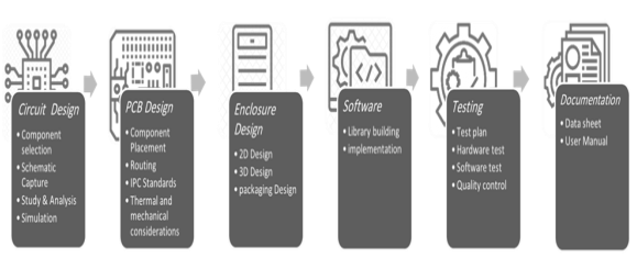
The design process of the device will be as Figure 3.5 bellow. First, we will design the circuit as the initial and the basic stage in the design workflow, we will select the needed components for the purpose of device function considering various things like cost, size, specification, availability … etc. After the components selection we will use an electronic design automation tool in our case we will work on EasyEDA to design the schematic and the PCB board. To design the PCB, we will place the circuit component in an accurate way to make the PCB perform its functionality effectively, then we will do the routing and add proper wires to connect the components while obeying the IPC standard of designing PCB, then we will develop the software of the device by building a library containing the firmware of the product which will make it perform its expected function
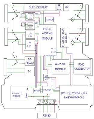
Block diagram
The Figure 3.8 presents the block diagram of our device. We have different modules performs different tasks and each module circuit have different hardware components picked carefully to make the device achieve its prober functionality.
3 System workflow
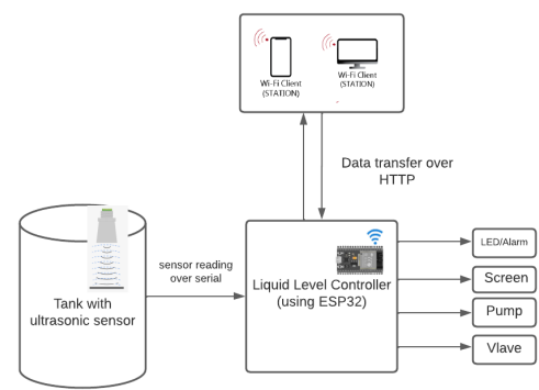
Figure 3.8 shows the system workflow, initially the controller will run a webserver and wait for clients to connect to it, after connection the client will setup configuration of the tank by determine the high and the low thresholds of the tank. The data transfer between the client and the controller will be over HTTP protocol.
Ultrasonic The method of measuring we used is the ultrasonic sensor it will send sound waves to the surface of the liquid and calculate the travelling time for the echo waves to turn back and use it to calculate the distance, based on that we can get the level measurement. Figure 3.10 shows the ultrasonic sensor measurement
VS Code and Platform IO: For testing the hardware and the controller we will use VS Code IDE as development environment, VS Code is a code editor used to build modern applications and it provides large functionality and extensions used to increase the productivity of building applications.
CONCLUSION
Tank level measurement problem is popular in industry and our project intends to give a solution in an automated way, to save money, effort, and increase the production in factories. The device implementation starts from the very low level of creating circuits and design PCB, to choose the appropriate controller and sensor and test it. The implementation considered remote configuration and controlling for the controller using Wi-Fi for the device, also it can be done in the embedded code. A major achievement of the device is to keep equipment from being destroyed to the greatest extent possible. Also, we were able to design a device well suited for industrial settings, such as pharmaceutical and food factories as well as water stations. Future enhancement:
1- control, monitor and regulate liquid level through the cloud.
2. Voice alarm system used when liquid level reaches a certain level.