
Interfacing WizFi360 WiFi Module to Teensy 4.0 MCU
I have been working on a new ‘standard’ MCU platform for future projects. In the past I’ve used the Teensy 3.2 for many projects.

Wiznet India Pvt Ltd - WizFi360io-H
x 1
I have been working on a new ‘standard’ MCU platform for future projects. In the past I’ve used the Teensy 3.2 for many projects. It is becoming a little long in the tooth and very difficult to find due to supply chain issues.
I’ve played with some other MCUs in the past year or so including the Arduino 33 IoT and the Raspberry Pi Pico. Both have left me wanting: Arduino 33 IoT and Raspberry Pi Pico Eval.
A few months ago I decided to see how I like the Teensy 4.0. It is pin compatible to the 3.2 but about 10X faster. Since everything I’m used to doing on the Teensy 3.2 works about the same on the 4.0, it seems like a great choice EXCEPT there still is no network connectivity.
For the 3.2, I used an external WizNet W5200 module to provide ethernet access. I was always quite happy with it. Going back to WizNet, they now have a WizFi360 module that provides WiFi access.
The downside to using Teensy 4.0/WizFi360 is the total price between these 2 devices is about $30. But I’m not expecting to do anything in the future that isn’t just one-off projects so I can live with the price if I don’t have to learn a bunch of new stuff.
Preliminary Stuff
Before making it to this point, I tested the WizFi360 module to make sure I could access it, documented here. I also uploaded the latest firmware, documented here.
Connecting WizFi360 to Teensy 4.0
As shown in the testing post above, I have soldered a WizFi360io-H to an XBEE breakout board:

and the pinouts for this device are:

Besides providing 3.3V and GND, I will only need to connect TXD1, RXD1, and RST to the Teensy (and for this post, RST will never get used, but I may want it in the future).
Here is the schematic for this project:

Disregard all the wires going out of the Teensy to the right. Those are IO lines for an OLED and navigation switch.
Power Supply Issue
I am NOT powering the WizFi360 from the Teensy. There is a separate 3.3V power supply that powers them both as shown in the schematic. The WizFi360 can consume up to 500mA which is way more than the Teensy’s 250mA limit. Trying to do so could blow the fuse on the Teensy.
To further make power confusing, if the USB connection is made to transfer software or to debug, then the Teensy will provide power to its 3.3V pins, risking the Teensy fuse. It is important to make sure the 3.3V power supply is enabled anytime the USB cable is connected.
This restriction can be removed by breaking the VIN/VUSB copper trace on the bottom of the Teensy. But once you do that you MUST provide a separate 3.3V power source to the Teensy.
I’m not yet ready to commit my Teensy to this change, so I will just be careful to make sure the 3.3V power supply is always running.
With a Blink sketch running on the Teensy, I apply power and can see both the Teensy and WizFi360 properly power up.
Here is a picture of my breadboarded Teensy/WizFi360:

You can disregard the OLED and Nav switch.
Installing the WizFi360 Library
Now we turn to software. WizNet has provided a library for the WizFi360. It is meant for either their Arduino Mega 2560 shield or their WizFi360 EVB Pico device, but with just a couple of snips of code, it will run fine on the Teensy.
First, download the library from here:
https://github.com/Wiznet/WizFi360_arduino_library
You will now have downloaded a ZIP file named WizFi360_arduino_library-main.zip.
To install this into the Arduino IDE:
- Start the Arduino IDE
- Open the Blink Example:

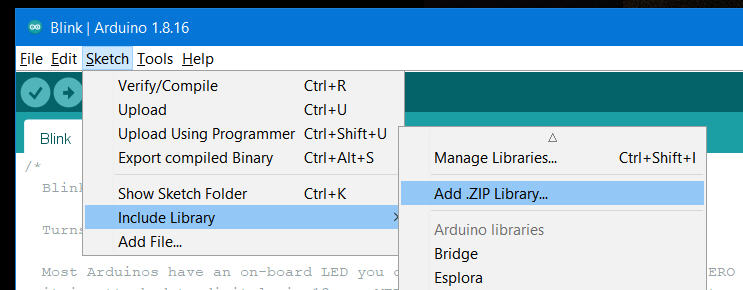
- Click on sketch | include library | Add Zip:
- Locate the zip file downloaded above in the file open box and double click on it.
- Now if you click on Sketch | Library, down at the bottom you will find the WizFi360 library:

If you add that library to the Blink sketch currently open, you will see several libraries added to the sketch:

The library is properly installed.
Testing the WizFi360 Module using the UdpNTPClient Example
- Now, in the IDE, click on File | Examples | WizFi360 | UdpNTPClient:

The NTP Client is now open in the IDE:

If you were to attempt to compile now, you would get errors because this program only knows how to run on a Mega or a Pico.
The only reason the sketch fails is because of how the Serial ports are defined. For the Teensy, Serial is the USB serial port where debugging normally is sent. Serial1 (pins 0 and 1) is the port connected to the WizFi360.
Since this is a quick and dirty test of the module, I’m going to butcher this program.
First, completely delete these lines:
// setup according to the device you use
#define ARDUINO_MEGA_2560

// Emulate Serial1 on pins 6/7 if not present
#ifndef HAVE_HWSERIAL1
#include "SoftwareSerial.h"
#if defined(ARDUINO_MEGA_2560)
SoftwareSerial Serial1(6, 7); // RX, TX
#elif defined(WIZFI360_EVB_PICO)
SoftwareSerial Serial2(6, 7); // RX, TX
#endif
#endif

/* Baudrate */
#define SERIAL_BAUDRATE   115200
#if defined(ARDUINO_MEGA_2560)
#define SERIAL1_BAUDRATE  115200
#elif defined(WIZFI360_EVB_PICO)
#define SERIAL2_BAUDRATE  115200
#endif
now, modify these lines to include the proper SSID and password for your WiFi network:
/* Wi-Fi info */
char ssid[] = "wiznet";       // your network SSID (name)
char pass[] = "0123456789";   // your network password
Now replace these lines:
  // initialize serial for debugging
  Serial.begin(SERIAL_BAUDRATE);
  // initialize serial for WizFi360 module
#if defined(ARDUINO_MEGA_2560)
  Serial1.begin(SERIAL1_BAUDRATE);
#elif defined(WIZFI360_EVB_PICO)
  Serial2.begin(SERIAL2_BAUDRATE);
#endif
  // initialize WizFi360 module
#if defined(ARDUINO_MEGA_2560)
  WiFi.init(&Serial1);
#elif defined(WIZFI360_EVB_PICO)
  WiFi.init(&Serial2);
#endif
with:
  // initialize serial for debugging
  Serial.begin(9600);
  // initialize serial for WizFi360 module
  Serial1.begin(115200);
  // initialize WizFi360 module
  WiFi.init(&Serial1);
Here is the modified section of the sketch that I am using:
#include "WizFi360.h"
#include "WizFi360Udp.h"

/* Baudrate */

/* Wi-Fi info */
char ssid[] = "Snippy";       // your network SSID (name)
char pass[] = "Snappy";   // your network password

int status = WL_IDLE_STATUS;  // the Wifi radio's status

char timeServer[] = "time.nist.gov";  // NTP server
unsigned int localPort = 2390;        // local port to listen for UDP packets

const int NTP_PACKET_SIZE = 48;  // NTP timestamp is in the first 48 bytes of the message
const int UDP_TIMEOUT = 2000;    // timeout in milliseconds to wait for an UDP packet to arrive

byte packetBuffer[NTP_PACKET_SIZE]; // buffer to hold incoming and outgoing packets

// A UDP instance to let us send and receive packets over UDP
WiFiUDP Udp;

void setup() {
  // initialize serial for debugging
  Serial.begin(9600);
  // initialize serial for WizFi360 module
  Serial1.begin(115200);
  // initialize WizFi360 module
  WiFi.init(&Serial1);

  // check for the presence of the shield
This I compile and upload and here is the program output seen on the serial monitor:
