
Home Automation Using Wi-Fi and Security System
Recently home automation is the most research project in automation field. This paper presents the implementations of home automation using
WIZnet - W5200
x 1
I. INTRODUCTION
In day to day life home automation plays an important role in human life. Home automation is the simplest way to save time. In home automation all electrical and electronic appliances are controlled automatically. The paper deals with operating home appliances manually using local area network and by using environment physical value i.e. automatic operation. A. Existing Home automation and its Analysis There are many available literatures which define the home automation system. In Microcontroller based home automation the home appliance are controlled from sensor value
[1]. This system is automated only from sensor value and if person want to control the fan speed that is not possible. Embedded system for home automation using SMS (Short message service) [2] defines that the home appliances are control from the SMS using GSM module. This system combines the circuit to GSM module that is connected through RS232 and it commands programming that we need to implement RS232 protocol. In this system there is need to check mobile network and SMS balance. Home automation is also done using GSM system which uses Zigbee sensor and two microcontrollers [3]. In that system GSM module are used to send SMS to the microcontroller that contain Zigbee transmitter module and other micro controller receives command from Zigbee receiver and then controls the home appliances. This is a big circuit, costly and more complicated for microcontroller programming. Home automation use Bluetooth, devices with the use of mobile Bluetooth to control the home appliances [4]. In that automation type mobile java programming is needed to send the command through SMS to Bluetooth model that is connected to microcontroller to control the home appliances. Wi-Fi based home automation is also one type of automation. In this system computer server are used and computers are connect to the Wi-Fi router. Computer controls home appliances through mobile web and internet [5]. The major drawback with this system is they are expensive and they need large space for installation. Home automation system using Arduino[6], such systems are developed to control the home appliances using Bluetooth and Wi-Fi shield from mobile application. It needs android mobile and home appliances are controlled via Wi-Fi and Bluetooth. Home automation using Raspberry Pi, Raspberry pi is small computer having Ethernet and Wi-Fi[7], in this system Raspberry pi used as server to control the home appliance by getting commands from mobile. It’s also needs to develop mobile application to control the home appliances via Wi-Fi. B. Features and Benefit of Home automation system Recently Wi-Fi router is commonly used in home and offices to connect broadband connection. Home automation uses this common Wi-Fi router to control home appliances through mobile and computer. The uses of Ethernet shield and Wi-Fi router have several advantages such asReduction of cost: In this system cost of installation is reduced because this is wireless system having existing Wi-Fi router, and all circuits will be/are installed in the existing electric board.
Easy to connect: Wi-Fi ranges have covered all home area so it is easy to connect Wi-Fi based mobile. Size: This system is easy to install existing electrical board so more space is not needed. Circuit development: Home automation circuit is simple to design. It contains microcontroller with actuator circuit and sensor interfacing. .
II. SYSTEM ARCHITECTURE
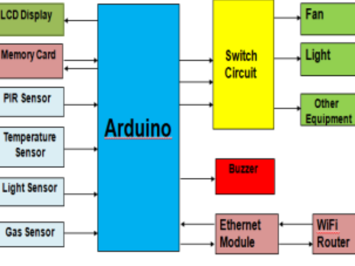
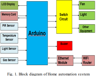
System architecture describes the block diagram of home automation using Wi-Fi (Fig.1). It consist of Arduino, Ethernet Module, switch circuit, memory card, Buzzer and Sensors. All the devices of this system are connected to the Arduino controller. Sensors are input devises that gives different environmental input parameters. LCD is the output device to show the value of sensor and massages. Switch circuit operates the electrical and electronic appliances. Buzzer is used to give loud sound when there is any problem in the system. Ethernet module is used as a communication device between controller and users. Wi-Fi router is connecting to the Ethernet module to share web file from memory cards. Fig. 1. Block diagram of Home automation system
III. MAJOR SYSTEM COMPONENT
The following major components used in the Home automation system. These are Arduno Mega, Ethernet shield, Switch Circuit, Temperature sensor, Light Sensor, Passive infrared sensor and gas sensor. A. Arduino Mega The Arduino mega is a microcontroller board based on ATmega 2560. It is work with simple mini USB cable instead of standard cable. The mega was designed and is being produced by RADIONICS. The Arduino Mega operates on regulated 5V power supply (Pin 52) and it requires 6V- 20V external power supply. It contains 16 analog and 56 digital input output pin. The Mega 2560 does not use FTDI USB to serial drive chip; instead it features the Atmega8U2 programmed as a USB to Serial converter. ATmega 2560 has 256 KB flash memory for storing code (in that 8 KB is used for the boot loader). It has 8 KB SRAM and 4 KB of EEPROM memories. ATmega contain four serial ports: Serial 0: Pin 0 (RX) and Pin 1(TX), Serial 1: Pin 19(RX) and Pin 18(TX), Serial 2: Pin 17 (RX) and Pin 16 (TX), Serial 3: Pin 15(RX) and Pin 14 (TX). It has SPI communication pin: Pin 50 (MISO), Pin 51(MOSI), Pin 52 (SCK) and Pin 53(SS). It also contains I2C communication Pin: Pin 20 (SDA) and Pin 21 (SCL).
B. Ethernet Shield:-
Ethernet shield is high speed Ethernet controller W5200. This supports up to eight simultaneous TCP/UDP connections. This shield has a Micro SD card slot to support data intensive project. It has minimal RJ-45 Port. Its require 5V power supply. Generally Ethernet shield is used to provide internet to microcontroller base project.
C. Switch Circuit:-
Switch circuit is combination of relay switches. Relay is the electromechanical switch which is operated by electrical supply. Relay is used to control high voltage devices using the low control isolated voltage. It is a 5 pin device having 2 pin for Input and 3 pin for output (Normal Open, common, and Normal closed).Input pin is internally connected with magnetic coil that energies when we apply 5V. When coil energies it switches output from normal open to normal closed mode. Switch circuit has LED indicator to show which relay is ON and OFF.
D. Temperature Sensor:-
In this system we used LM35 temperature sensor. It operates on 4V to 30V and its working range is -55 °C to 150 °C. It has low output impedance which calibrates directly in Celsius.
E. Light Sensor:-
In this system we are using LDR as a light sensor. LDR is a Photo resistor that is light controlled variable resistance. It contains two photo conducting cells. The cell resistance increases when the light intensity is increased. It is also used as smoke detector.
F. Passive infrared Sensor:-
This is used for human body detection. It operates on 5V DC supply. Passive infrared sensor has detection range of 6 meter and it is a dual element sensor with low noise and high sensitivity sensor
G. Gas Sensor:-
In home automation system we used MQ 2 sensor as a Gas sensor. MQ 2 sensor is made from SnO2 sensitive material, which has low conductivity in clean air. The sensors conductivity is higher along with the rising gas concentration. This sensor has high sensitivity to LPG, Propane, and Hydrogen.
IV. SYSTEM IMPLEMENTATION
Proposed home automation system is based on three modules; the hardware interfacing, Software programming and user interface and Security System '
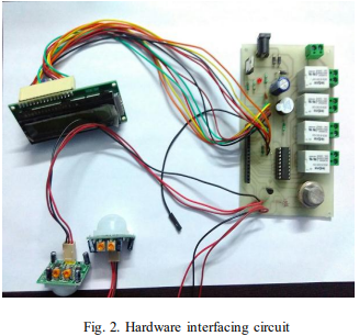
A. Hardware Interfacing In this system, Input devices are sensors that interface with the Arduino controller. Arduino controller gathers the environmental physical parameters such as temperature, Light intensity, Human interface, and gas sensor from sensor. Using this value controller gave instructions to the switch circuit to operate home appliances. Buzzer and LCD is output device that interface with microcontroller. ATmega 2560 uses Serial Peripheral interface (SPI) to communicate with Ethernet module. This Ethernet module uses SPI to communicate with memory card. Users communicate to the control signal through Wi-Fi router which is connected to Ethernet Module via Ethernet cable. Interfacing of hardware components using Ethernet is reducing the complexity of the circuit. Fig. 2. Hardware interfacing circuit
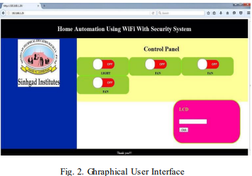
B. Intranet Base Graphical User Interface The home automation system used in this project is designed to use the intranet base user screen. Embedded hardware interface application is implemented in the Arduino compiler. If the users are aware of knowledge about standard browser such as internet explorer, chrome etc. they can easily control this system via browser. This screen is implemented in server by using HTTML and java scrip. Users can easily access the graphic user interface control screen through intranet link (https:// 192.168.1.20). Users should have knowledge of mobile and windows operating system. Fig. 2. Ghraphical User Interface
C. Security System The home automation system contains PIR sensor, GAS sensor and temperature sensor for security purpose. PIR sensor is placed on windows to monitor any human entry and if it is observed, this sensor give signals to controller and buzzer will start. If there is gas leakage then gas sensor will detect this and send signal to controller to start buzzer. Temperature sensor will sense rise in temperature caused by any accidental burns in the home.
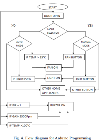
D. Software Interface This home automation system make using of Arduino base compiler. Software programming is made in embedded C. The aurdino compiler is freeware software and it has many tasted libraries. This system consists of standard library for LCD, Ethernet shield and web programming. The standard library is easy to call the instruction in any position. Web base HTTML and java scrip programming are in memory card. Controller is made up of programming that calls web files from memory card to Ethernet shield and shows them in mobile application through intranet link Fig.4. shows flow chart of programming. When the door of home is opened the program will directly go to auto mode and start the home appliances with reference to the sensor value. If we select the manual mode then all the appliances will be controlled manually through the mobile or laptop that access controller through Wi-Fi connectivity. International Engineering Research Journal Page No 2043-2046 Fig. 4. Flow diagram for Arduino Programming
V. RESULT
This paper show the implementation of home automation using Wi-Fi and Security system the microcontroller controls the Fan, Light and other appliances through Relay circuit. User can operate and check status of home appliances from web base user friendly graphic interface. In Auto mode when home temperature rises above 25°C fan start and stop below 25°C. Light start when light intensity above 50% and gets off below 50% intensity. Other appliances like TV and AC starts in auto mode automatically when operated from its remote. In Manual Mode we have operated all appliances manually on intranet bas e graphic interface. For security purpose, Gas intensity more than 3000 ppm then buzzer activated and it stop below 3000ppm. If Temperature is more than 100°C then buzzer will activated. Placed one PIR on window, If anyone trying to enter from window then PIR detect the motion and buzzer will activated for 60 sec.
VI. CONCLUSION
Recently, Home automation is the most important and promising fields now days in developed homes. In this project, we successfully developed home automation using Wi-Fi Router and security system. Project is easily implemented in existing electric board. The project reduces the cost of extra server such as computer or Raspberry Pi type microprocessor. Project is comfortable for user to access auto and manual mode of control. Project tasted on to the four appliances in between two appliances (fan and light) are controlled through sensor in Auto mode. Security system verified to use Gas and unwanted human interference.
VII. ACKNOWLEDGMENT
I would like to thanks Prof S.A. Kulkarni and Prof. M.N. Kakatkar of Sinhgad College of Engineering Pune, for their guidance in technical documentation and invaluable support.