---
title: "BMS-Fake-WiFi(Smart Battery Management System)"
url: "https://maker.wiznet.io/irina/projects/bms-fake-wifi-smart-battery-management-system/"
markdown_url: "https://maker.wiznet.io/irina/projects/bms-fake-wifi-smart-battery-management-system/md"
type: "UCC: User Created Content"
author: "QDarkRex"
author_url: "https://github.com/QDarkRex/BMS-Fake-WiFi"
editor: "WIZnet"
editor_url: "https://maker.wiznet.io/"
original_author: "QDarkRex"
original_url: "https://github.com/QDarkRex/BMS-Fake-WiFi"
published: "2026-07-06"
language: "en"
likes: 0
views: 207
comments: 0
source: "WIZnet Makers (https://maker.wiznet.io/)"
---
# BMS-Fake-WiFi(Smart Battery Management System)
> Arduino Mega 2560 firmware for a 4-cell Li-ion BMS by @QDarkRex, with per-cell protection and a W5500 Ethernet web dashboard + REST API. (from Indonesia)
Original author: QDarkRex (source: https://github.com/QDarkRex/BMS-Fake-WiFi)
## Documents and links
- [Schematic_FakeWifiBMSControl_2026-06-24.pdf](https://github.com/QDarkRex/BMS-Fake-WiFi/blob/main/docs/Schematic_FakeWifiBMSControl_2026-06-24.pdfㅍ) (schematics): schematic
- [HANDOVER.md](https://github.com/QDarkRex/BMS-Fake-WiFi/blob/main/HANDOVER.md): full handover (hardware, as-built mods, firmware, build, calibration, issues)
- [API_COMMANDS.md](https://github.com/QDarkRex/BMS-Fake-WiFi/blob/main/API_COMMANDS.md): complete REST API endpoint list
- [USER_GUIDE.md](https://github.com/QDarkRex/BMS-Fake-WiFi/blob/main/USER_GUIDE.md): plain-language guide (LEDs, button, charging, safety)
- [DEVELOPMENT_NOTES.md](https://github.com/QDarkRex/BMS-Fake-WiFi/blob/main/DEVELOPMENT_NOTES.md): development journey (decisions & "why")
## Article
### 프로젝트가 하는 일
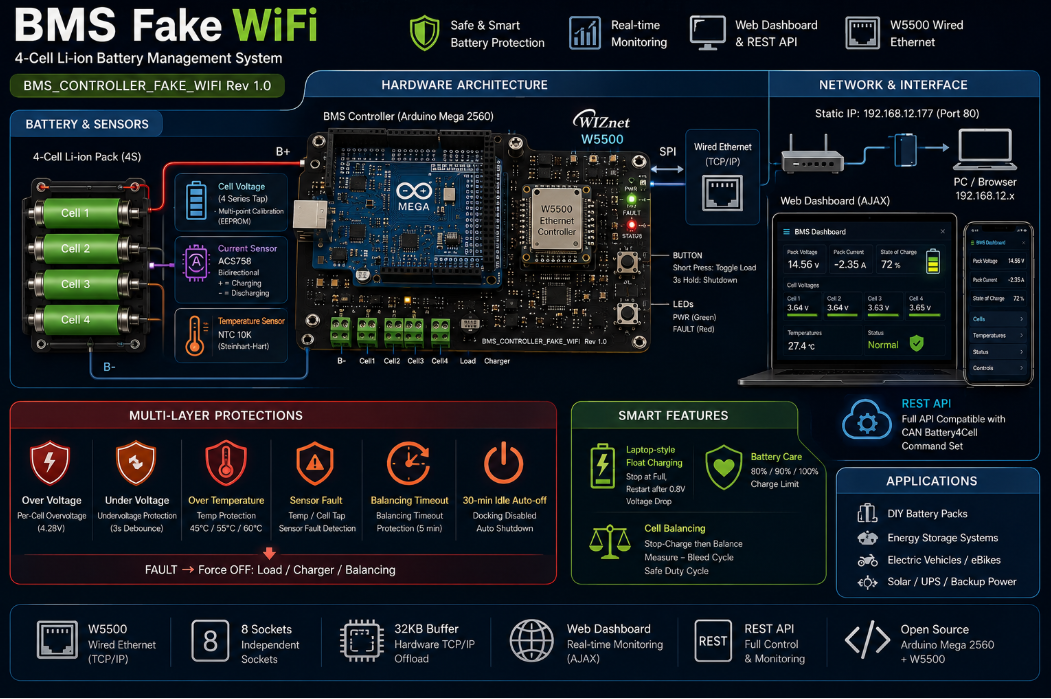
**BMS Fake WiFi**는 **Arduino Mega 2560(ATmega2560)** 펌웨어로 구현한 **4직렬(4S) LiPo 배터리 관리 시스템(BMS)** 입니다. 보드는 `BMS_CONTROLLER_FAKE_WIFI` Rev 1.0이며, **W5500 유선 Ethernet 기반의 웹 대시보드 + REST API**로 배터리 상태를 실시간 모니터링·제어합니다.
기본 배터리 파라미터: **만충 4.125V/셀(팩 16.5V)**, **방전 하한 3.05V/셀**, **셀 과전압 보호 트립 4.28V**.
- **셀별 전압**: 4직렬 누적 탭(A0–A3, LM358 op-amp 경유) → 셀별 차분 계산 + EEPROM에 저장되는 **다점 보정**(gain+offset, 최소자승)
- **SOC**: LiPo OCV 룩업 + 보간, EMA 평활 (`vmin`=0%, `vmax/4`=100%로 스케일)
- **전류**: ACS758-100B(+MAX4213) 양방향 (+충전/−방전)
- **온도**: NTC 10K 서미스터(Steinhart-Hart), 펌웨어에 `TEMP_OFFSET=4.0°C` 보정
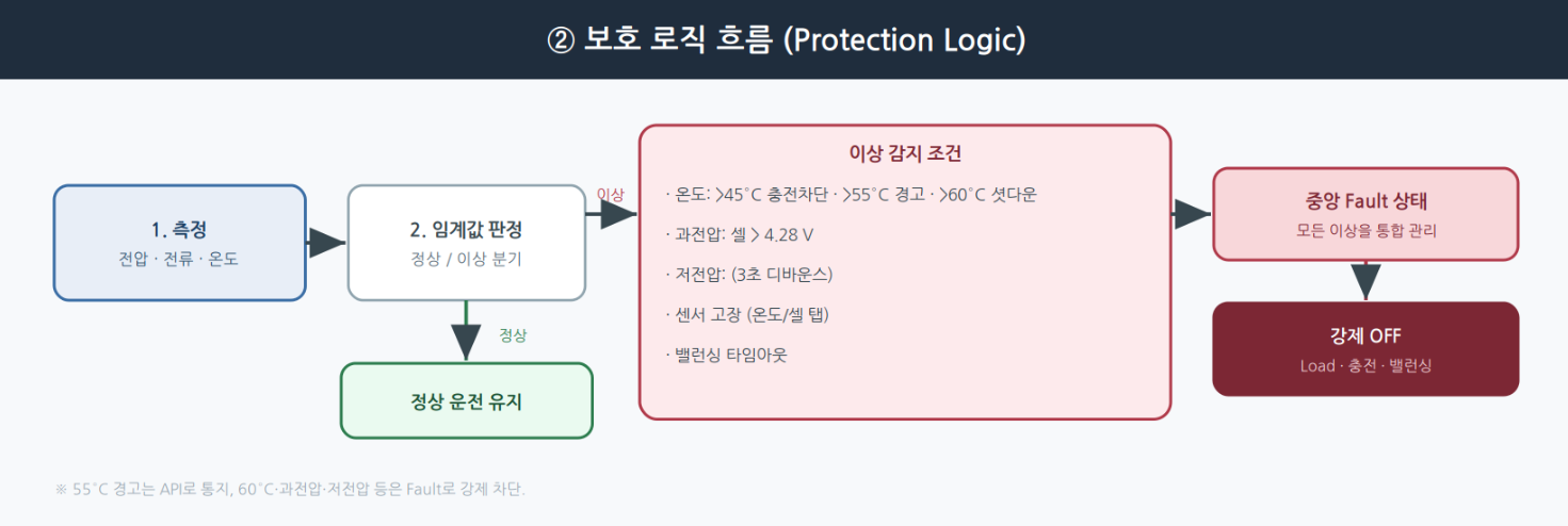
- **다단계 온도 보호**: 45°C↑ 충전 차단 · 55°C↑ 경고(API) · 60°C↑ 셧다운(3초 디바운스)
- **셀 과전압(4.28V) / 저전압(기본 3.05V)** 보호
- **중앙 Fault 상태(bitmask)**: `temp_sensor`·`overheat_critical`·`cell_sensor`·`cell_overvoltage`·`cell_undervoltage`·`manual_balance_timeout` → 하나라도 활성 시 **Load/충전/밸런싱 강제 OFF**, LED 적청 스트로브, API는 `output_blocked_fault` 반환
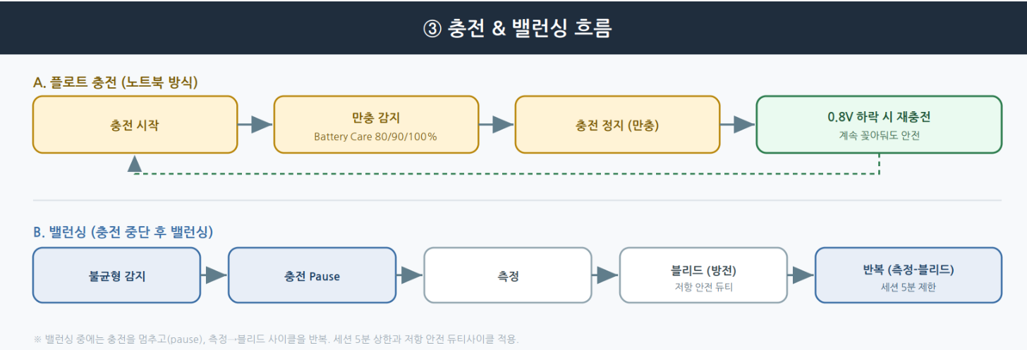
- **노트북식 플로트 충전**: 만충 정지, 0.8V 하락 후 재충전 + **Battery Care**(longevity 16.0V ≈80% / balanced 16.4V ≈90% / full 16.5V =100%)
- **밸런싱(패시브, 충전 중단 후)**: 충전 PAUSE → 측정(1.5s)/블리드(2s) 반복 → 셀 편차 **<8mV** 도달 시 충전 재개, 세션 **5분** 상한, 블리드 저항 39Ω 2512 1W
- **LED/버튼**: 배터리 RGB LED + WS2811 상태 LED, 버튼 짧게=Load 토글 / 3초=종료(웨이크 가드)
- **웹 대시보드(AJAX) + REST API**: CAN Battery4Cell 명령셋을 반영
### WIZnet이 들어가는 위치
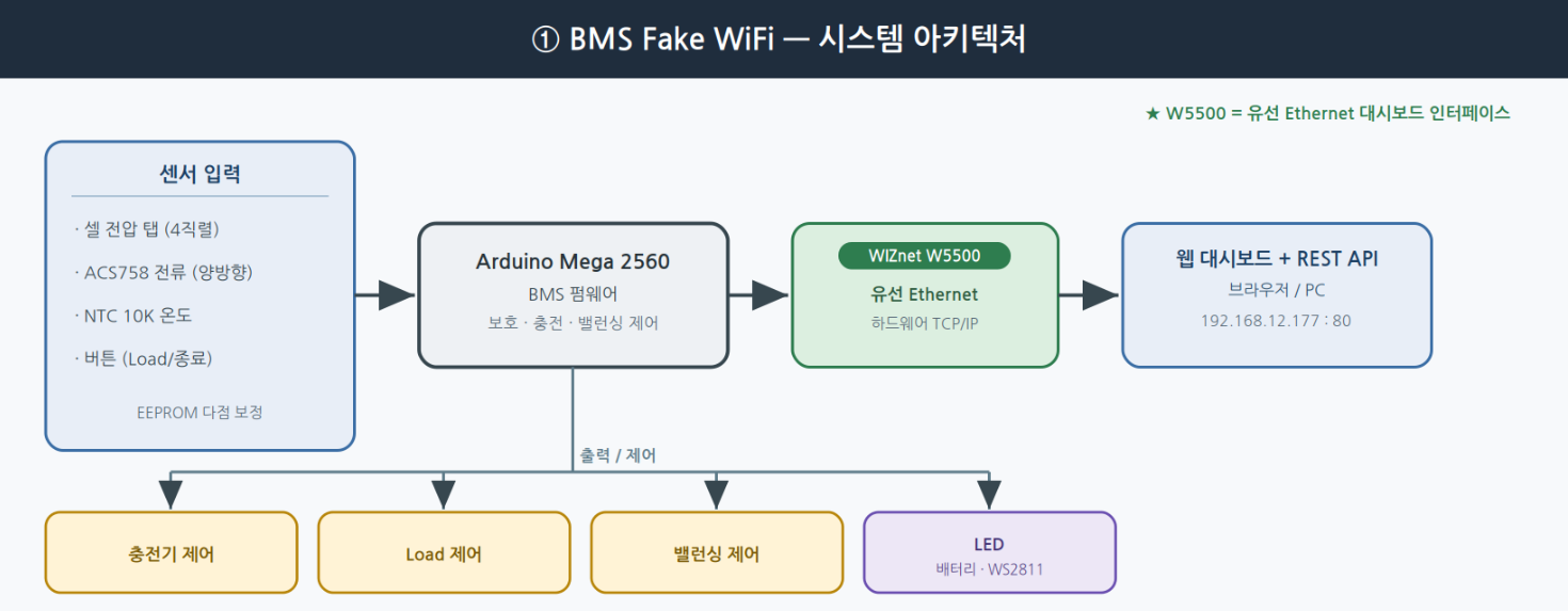
이 프로젝트에서 사용되는 WIZnet 제품은 **W5500**이며, Arduino Mega 2560에 **유선 Ethernet 인터페이스**(SPI, **CS=D53 / RST=D4**)를 제공합니다. BMS 상태(셀 전압·전류·온도·SOC·Fault)를 **웹 대시보드와 REST API로 실시간 모니터링·제어**하는 통로입니다. W5500은 하드웨어 TCP/IP 스택·SPI·8소켓·32KB 버퍼를 제공하므로, MCU가 배터리 보호/제어 로직에 집중하는 동안 안정적인 유선 네트워크를 담당합니다. 기본 정적 IP `192.168.12.177`(포트 80), PC는 `192.168.12.x` 서브넷. CORS 개방(`*`), 모든 엔드포인트 GET, 웹서버는 단일 스레드.
### 핀맵 (firmware ↔ hardware)
| 기능 | 핀 | 비고 |
| --- | --- | --- |
| 전원 래치 | D2 | HIGH=유지, LOW=완전 종료 |
| **W5500 RST / CS** | **D4 / D53** | SPI 버스 |
| Load FET | D27 | beban 출력 |
| 충전 리턴 FET | D28 | charge− 경로 |
| 충전기+ P-FET (Q21) | D10 | charger+ 게이트 |
| 버튼(opto) | A8 | `analogRead > 1000` |
| 서미스터 | A6 | NTC 10K (TEMP_1) |
| 셀 탭 (총·3·2·1) | A3 / A1 / A2 / A0 | LM358 op-amp 경유(누적) |
| 전류 센서 | A4 | ACS758-100B + MAX4213 |
| 밸런싱 FET 1..4 | D3 / D5 / D7 / D9 | 셀별 블리드 |
| 배터리 RGB LED | D25 / D23 / D24 | 용량/충전/위험 |
| WS2811 상태 LED | D22 | addressable |
### REST API (요약)
Base URL `http://192.168.12.177` · 모두 GET · JSON 응답(대시보드 계열은 204).
**센서/상태 읽기**: `GET /api/all`(한 번에 스냅샷) · `/api/cells` · `/api/cell?n=1` · `/api/current` · `/api/temperature` · `/api/capacity` · `/api/status` · `/api/faults` · `/api/v2/telemetry`(구조화 envelope). 상태코드 0=Idle,1=Charging,2=Balancing,3=Load.
**제어**: `GET /api/control?cmd=charge_on|charge_off|load_on|load_off|balance_on|balance_off|shutdown` (Fault lockout 시 `charge_on/load_on/balance_on`은 `output_blocked_fault`로 거부, 수동 밸런싱은 5분 하드 타임아웃).
**설정/보정**: `/api/set_vmax?value=16.5` · `/api/set_vmin?value=3.05` · `/api/battery_care?mode=longevity|balanced|full` · `/api/set_time?epoch=&tz=` · `/api/cal_add` → `/api/cal_compute`(다점 보정) · `/api/cal_get|cal_status|cal_reset|cal_debug` · `/api/eeprom_reset`.
**LED**: `POST /api/v1/led` (body `{"app":true,"state":"idle|scanning|attacking","alfa":3}`) · `GET /api/v1/led`. LED 상태는 관련 프로젝트에서 온 표시용 라벨이며 BMS 동작과는 무관.
> 폴링 권장: `GET /api/all` 하나로 1초 간격, 요청 중첩 금지(클라이언트 타임아웃 ~2초). 전체 목록은 저장소 `API_COMMANDS.md` 참고.
### 구현 메모
- **빌드**: Arduino IDE에서 `main/` 폴더를 열고 보드를 **Arduino Mega 2560**으로 선택 후 Upload. 필요한 라이브러리는 **Ethernet**, **Adafruit_NeoPixel**.
- **네트워크**: 정적 IP `192.168.12.177`(포트 80). 대시보드는 `main/eth.ino`의 웹 서버가 제공.
- **파일 구조**:
| 파일 | 내용 |
| --- | --- |
| `main/main.ino` | Setup·loop·핀·전역변수·EEPROM |
| `main/percell_voltage.ino` | 셀 전압 읽기 + 밸런싱 로직 + 보정 |
| `main/current.ino` | ACS758 전류 센서 읽기 |
| `main/temp.ino` | 온도 읽기 + 온도 기반 충전 보호 |
| `main/control.ino` | 버튼·자동 종료·배터리 LED·WS2811 상태 LED |
| `main/eth.ino` | 웹 서버·대시보드 HTML·REST API |
> API 엔드포인트 전체 목록은 저장소의 `API_COMMANDS.md`, 배선/보정/이슈 등은 `HANDOVER.md`를 참고하세요.
### ⚠️ 안전 주의 (리튬 배터리)
리튬이온 배터리는 **과충전·과방전·과열·단락 시 발화·폭발 위험**이 있습니다. 이 프로젝트가 다단계 보호를 제공하더라도, 실제 구성·시험 시에는 셀 사양 준수, 적절한 퓨즈/보호회로, 온도 감시, 관리·감독이 필수입니다. 이 글은 프로젝트 소개용이며 안전 설계·인증을 대체하지 않습니다.
### 유사 프로젝트
두 프로젝트는 모두 **W5500 유선 Ethernet으로 센서 데이터를 수집·모니터링하는 시스템**이라는 점에서 유사합니다. 다만 BMS Fake WiFi는 **배터리 보호·충전·밸런싱까지 제어하는 배터리 관리 시스템**이고, ssekim의 글은 **산업 모니터링용 범용 센서 시스템의 Ethernet 서브시스템** 설명에 가깝습니다.
| 항목 | BMS Fake WiFi | Simple Sensor System (Industrial) |
| --- | --- | --- |
| 목적 | 배터리 관리·보호·제어 | 산업 센서 모니터링 |
| 대상 | 4셀 Li-ion 팩 | 범용 센서 |
| MCU | Arduino Mega 2560 | (Ethernet 서브시스템 중심) |
| 제어 | 충전/밸런싱/보호 능동 제어 | 주로 데이터 수집 |
| 인터페이스 | 웹 대시보드 + REST API | Ethernet 데이터 경로 |
| W5500 역할 | 유선 모니터링/제어 인터페이스 | 유선 데이터 인터페이스 |
### FAQ
**Q: 이름이 "Fake WiFi"인데 공격 도구인가요?** A: 아니요. 로그 AP나 이블트윈 같은 공격 기능이 전혀 없습니다. 보드 별명(`BMS_CONTROLLER_FAKE_WIFI`)에서 온 것으로, **유선 W5500 이더넷으로 무선 대시보드처럼 쓴다**는 의미입니다. 실체는 배터리 관리 시스템입니다.
**Q: 무엇을 관리하나요?** A: 4직렬 리튬이온 셀의 전압/전류/온도를 측정하고, 과전압·저전압·과열 보호와 충전·밸런싱을 수행합니다.
**Q: W5500은 어떤 역할인가요?** A: Arduino Mega 2560에 유선 이더넷을 부여해, 웹 대시보드와 REST API로 BMS 상태를 실시간 모니터링·제어하는 네트워크 인터페이스입니다.
**Q: 어떻게 접속하나요?** A: 기본 정적 IP `192.168.12.177`(포트 80). PC를 `192.168.12.x` 서브넷에 두고 브라우저로 접속합니다.
---
## What the Project Does
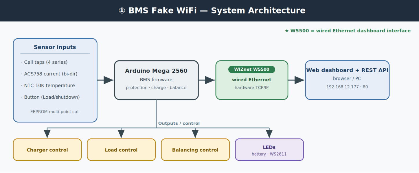
**BMS Fake WiFi** is a **4-series (4S) LiPo Battery Management System** implemented as **Arduino Mega 2560 (ATmega2560)** firmware. The board is `BMS_CONTROLLER_FAKE_WIFI` Rev 1.0, and it monitors/controls the battery through a **web dashboard + REST API over W5500 wired Ethernet**.
Default battery parameters: **full 4.125 V/cell (pack 16.5 V)**, **empty floor 3.05 V/cell**, **per-cell overvoltage trip 4.28 V**.
- **Per-cell voltage**: cumulative taps (A0–A3 via LM358 op-amps) → per-cell by difference + EEPROM **multi-point calibration** (gain+offset, least-squares)
- **SOC**: LiPo OCV lookup + interpolation, EMA smoothing (scaled `vmin`=0%, `vmax/4`=100%)
- **Current**: ACS758-100B (+MAX4213) bidirectional (+ charging / − discharging)
- **Temperature**: NTC 10K thermistor (Steinhart-Hart), firmware `TEMP_OFFSET=4.0 °C`
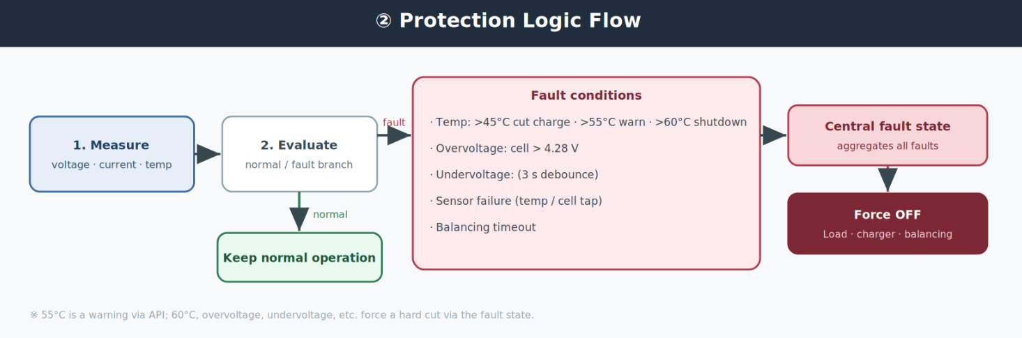
- **Tiered thermal protection**: >45 °C cut charge · >55 °C warning (API) · >60 °C shutdown (3 s debounce)
- **Per-cell overvoltage (4.28 V) / undervoltage (default 3.05 V)** protection
- **Central fault state (bitmask)**: `temp_sensor`·`overheat_critical`·`cell_sensor`·`cell_overvoltage`·`cell_undervoltage`·`manual_balance_timeout` → any active forces **Load/charger/balancing OFF**, red-blue LED strobe, API returns `output_blocked_fault`
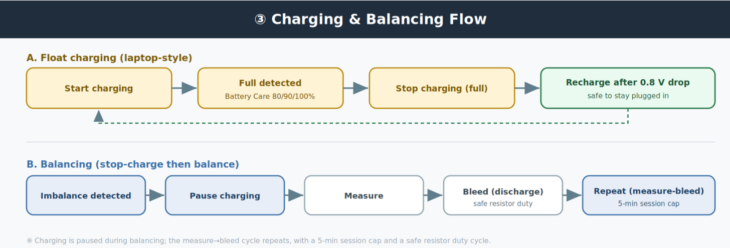
- **Laptop-style float charging**: stop at full, recharge only after a 0.8 V drop, plus **Battery Care** (longevity 16.0 V ≈80% / balanced 16.4 V ≈90% / full 16.5 V =100%)
- **Balancing (passive, stop-charge)**: pause charger → measure(1.5 s)/bleed(2 s) cycles → resume when cell delta **<8 mV**, 5-min session cap, 39 Ω 2512 1 W bleed resistor
- **LEDs/button**: battery RGB LED + WS2811 status LED, button short = toggle Load / 3-s hold = shutdown (wake guard)
- **Web dashboard (AJAX) + REST API**: mirrors the CAN Battery4Cell command set
## Where WIZnet Fits
The WIZnet product used is the **W5500**, giving the Arduino Mega 2560 a **wired Ethernet interface** (SPI, **CS=D53 / RST=D4**). It is the path by which BMS state (cell voltages, current, temperature, SOC, faults) is **monitored and controlled in real time via a web dashboard and REST API**. With its hardware TCP/IP stack, SPI, 8 sockets, and 32 KB buffer, the W5500 handles a stable wired network while the MCU focuses on battery protection/control. Default static IP `192.168.12.177` (port 80), PC on the `192.168.12.x` subnet, CORS open (`*`), all endpoints GET, single-thread web server.
## Pin Map (firmware ↔ hardware)
| Function | Pin | Notes |
| --- | --- | --- |
| Power latch | D2 | HIGH=stay on, LOW=full off |
| **W5500 RST / CS** | **D4 / D53** | SPI bus |
| Load FET | D27 | load output |
| Charge return FET | D28 | charge− path |
| Charger+ P-FET (Q21) | D10 | charger+ gate |
| Button (opto) | A8 | `analogRead > 1000` |
| Thermistor | A6 | NTC 10K (TEMP_1) |
| Cell taps (total·3·2·1) | A3 / A1 / A2 / A0 | via LM358 op-amps (cumulative) |
| Current sensor | A4 | ACS758-100B + MAX4213 |
| Balancing FET 1..4 | D3 / D5 / D7 / D9 | per-cell bleed |
| Battery RGB LED | D25 / D23 / D24 | capacity/charge/danger |
| WS2811 status LED | D22 | addressable |
## REST API (summary)
Base URL `http://192.168.12.177` · all GET · JSON responses (dashboard-family returns 204).
**Sensor/state reads**: `GET /api/all` (single snapshot) · `/api/cells` · `/api/cell?n=1` · `/api/current` · `/api/temperature` · `/api/capacity` · `/api/status` · `/api/faults` · `/api/v2/telemetry` (structured envelope). Status codes 0=Idle, 1=Charging, 2=Balancing, 3=Load.
**Control**: `GET /api/control?cmd=charge_on|charge_off|load_on|load_off|balance_on|balance_off|shutdown` (under fault lockout, `charge_on/load_on/balance_on` are rejected with `output_blocked_fault`; manual balancing has a 5-min hard timeout).
**Config/calibration**: `/api/set_vmax?value=16.5` · `/api/set_vmin?value=3.05` · `/api/battery_care?mode=longevity|balanced|full` · `/api/set_time?epoch=&tz=` · `/api/cal_add` → `/api/cal_compute` (multi-point) · `/api/cal_get|cal_status|cal_reset|cal_debug` · `/api/eeprom_reset`.
**LED**: `POST /api/v1/led` (body `{"app":true,"state":"idle|scanning|attacking","alfa":3}`) · `GET /api/v1/led`. These LED states are display-only labels inherited from a related project and are unrelated to BMS operation.
> Polling: use a single `GET /api/all` at a 1-second interval; do not overlap requests (client timeout ~2 s). Full list in the repo's `API_COMMANDS.md`.
## Implementation Notes
- **Build**: open the `main/` folder in Arduino IDE, select **Arduino Mega 2560**, then Upload. Required libraries: **Ethernet**, **Adafruit_NeoPixel**.
- **Network**: static IP `192.168.12.177` (port 80). The dashboard is served by the web server in `main/eth.ino`.
- **File structure**:
| File | Contents |
| --- | --- |
| `main/main.ino` | setup·loop·pins·globals·EEPROM |
| `main/percell_voltage.ino` | cell voltage read + balancing + calibration |
| `main/current.ino` | ACS758 current sensor read |
| `main/temp.ino` | temperature read + charge protection by temp |
| `main/control.ino` | button·auto-shutdown·battery LED·WS2811 status LED |
| `main/eth.ino` | web server·dashboard HTML·REST API |
> See `API_COMMANDS.md` for the full endpoint list and `HANDOVER.md` for wiring/calibration/known issues.
## ⚠️ Safety Note (Lithium Batteries)
Lithium-ion cells can **catch fire or explode if overcharged, over-discharged, overheated, or short-circuited**. Even though this project provides multi-layer protection, real builds and tests require adherence to cell specifications, proper fuses/protection circuits, temperature monitoring, and supervision. This write-up is an introduction and does not replace proper safety design and certification.
## Similar Project
Both projects are similar in that they **collect and monitor sensor data over W5500 wired Ethernet**. However, BMS Fake WiFi is a **battery management system that also controls protection, charging, and balancing**, while ssekim's article is closer to describing the **Ethernet subsystem of a general-purpose industrial monitoring sensor system**.
| Item | BMS Fake WiFi | Simple Sensor System (Industrial) |
| --- | --- | --- |
| Purpose | Battery management/protection/control | Industrial sensor monitoring |
| Target | 4-cell Li-ion pack | General sensors |
| MCU | Arduino Mega 2560 | (Ethernet-subsystem centric) |
| Control | Active charge/balance/protection | Mostly data collection |
| Interface | Web dashboard + REST API | Ethernet data path |
| W5500 role | Wired monitoring/control interface | Wired data interface |
## FAQ
**Q: The name says "Fake WiFi" — is it an attack tool?** A: No. It has no rogue-AP or evil-twin functionality. The name comes from the board nickname (`BMS_CONTROLLER_FAKE_WIFI`) — it uses **wired W5500 Ethernet as if it were a wireless dashboard**. It is a battery management system.
**Q: What does it manage?** A: It measures voltage/current/temperature of 4 series Li-ion cells and performs overvoltage/undervoltage/overheat protection plus charging and balancing.
**Q: What role does the W5500 play?** A: It gives the Arduino Mega 2560 wired Ethernet so the BMS state can be monitored/controlled in real time via a web dashboard and REST API.
**Q: How do I connect?** A: Default static IP `192.168.12.177` (port 80). Put your PC on the `192.168.12.x` subnet and open it in a browser.
---
Source: https://maker.wiznet.io/irina/projects/bms-fake-wifi-smart-battery-management-system/