
FPGA controls W5500 to complete UDP loopback test
FPGA controls W5500 to complete UDP loopback test

WIZnet - W5500
x 1
FPGA controls W5500 to complete UDP loopback test
1 Preface
2 Preparations
3 W5500 register description
4 W5500 loopback test
4.1 W5500 initialization
4.1.1 General Register Initialization
4.1.2 socket register initialization
4.2 W5500 data reception
4.3 W5500 data transmission
4.4 Data Loopback
5 summary
1 Preface
This article is aimed at people who already have a certain understanding of W5500 and have read the data manual. Because the blogger has only completed the UDP loopback test so far, only the UDP part may be introduced later.
2 Preparations
1.FPGA core board or development board;
2.W5500 module. The figure below is the module used by the blogger;

————————————————
3. Network debugging assistant, just find one on the Internet;
3 W5500 register description
There is a fixed protocol (data frame) between the host and W5500. The host first sends a two-byte register address, then a one-byte control word, and finally data. This data can be one byte or N bytes. , but for the convenience of operation, W5000 can divide this N into 1, 2, 4 and variable lengths, all of which can be configured. The image below is the data frame format.
————————————————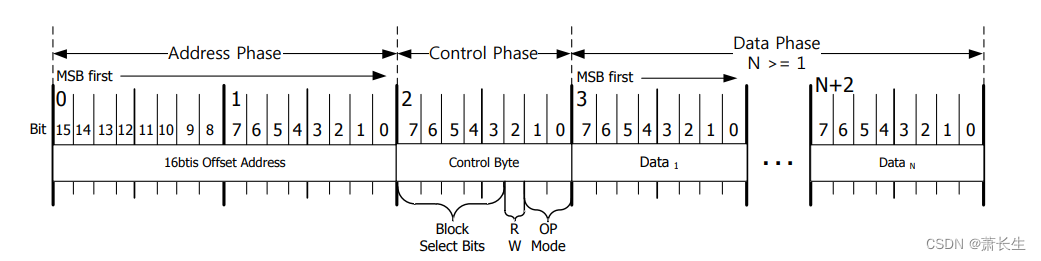
The figure below is the control field register, BSB4~BSB0 selection register, RWB is the read and write selection bit (1: write 0: read), OM selects the number of bytes of N in the data segment.

The registers of W5500 are divided into two types, one is general-purpose registers, and the other is socket registers. These two registers are selected by the address segment in the data frame, as shown in the figure below. For example, when the register address is 16'h0000, if the BSB is 5'h00000, then the MR register in the general register is selected at this time; if the BSB is 5'h00001, then the Sn_MR register in the socket0 register is selected at this time .

4 W5500 loopback test
4.1 W5500 initialization
4.1.1 General Register Initialization
The initialization of the general register is to configure the source gateway, subnet mask , MAC address, IP address, PHY register, and then clear the interrupt.
always@(posedge clk,negedge rst_n)
	if(!rst_n)
		o_dat<='d0;
	else begin
		case(state)
			WR_MR://WRMR_CMD,
				o_dat<=8'h00;
			WRGAR_CMD,WR_GAR:
				if(rdreq)
					case(cnt_byte)
							'd00:o_dat<=GAR[31:24];
							'd01:o_dat<=GAR[23:16];
							'd02:o_dat<=GAR[15:08];
							'd03:o_dat<=GAR[07:00];
						default:;
					endcase
				else
					o_dat<=o_dat;
			WR_SUBR://WRSUBR_CMD,
				if(rdreq)
					case(cnt_byte)
							'd00:o_dat<=SUBR[31:24];
							'd01:o_dat<=SUBR[23:16];
							'd02:o_dat<=SUBR[15:08];
							'd03:o_dat<=SUBR[07:00];
						default:;
					endcase
				else
					o_dat<=o_dat;
			WR_SHAR://WRSHAR_CMD,
				if(rdreq)
					case(cnt_byte)
							'd00:o_dat<=SHAR[47:40];
							'd01:o_dat<=SHAR[39:32];
							'd02:o_dat<=SHAR[31:24];
							'd03:o_dat<=SHAR[23:16];
							'd04:o_dat<=SHAR[15:08];
							'd05:o_dat<=SHAR[07:00];
						default:;
					endcase
				else
					o_dat<=o_dat;
			WR_IP://WRIP_CMD,
				if(rdreq)
					case(cnt_byte)
							'd00:o_dat<=SIPR[31:24];
							'd01:o_dat<=SIPR[23:16];
							'd02:o_dat<=SIPR[15:08];
							'd03:o_dat<=SIPR[07:00];
						default:;
					endcase
				else
					o_dat<=o_dat;
			WRIR_CMD,WR_IR,WRIMR_CMD,WR_IMR:
				o_dat<=8'hFF;
			WR_RTR://WRRTR_CMD,
				if(rdreq)
					case(cnt_byte)
							'd00:o_dat<=8'h07;
							'd01:o_dat<=8'hD0;
						default:;
					endcase
				else
					o_dat<=o_dat;
			WRRCR_CMD,WR_RCR:
				o_dat<=8'h08;
			WRPHY_CMD,WR_PHY:
				o_dat<=8'b11111111;
			default:o_dat<=8'h00;
		endcase
	end
4.1.2 socket register initialization
The configuration of socket registers is similar to that of general-purpose registers. First configure the destination socket mode (TCP, UDP, MACRAW), MAC address, destination IP address, destination port, and local port registers, then clear interrupts, etc., and finally configure the Sn_CR register to open the port, and then It is to query the SN_SR register regularly and wait for the socket to be initialized successfully (the value of the Sn_SR register is 8'h22).
————————————————
版权声明:本文为CSDN博主「萧长生」的原创文章,遵循CC 4.0 BY-SA版权协议,转载请附上原文出处链接及本声明。
原文链接:https://blog.csdn.net/changshengxiao/article/details/128124140
always@(posedge clk,negedge rst_n)
	if(!rst_n)
		o_dat<='d0;
	else begin
		case(state)
			WR_MR:
				o_dat<=8'h02;
			WR_IR,WR_IMR:
				o_dat<=8'hFF;
			WR_PORT:
				if(rdreq)
					case(cnt_byte)
						'd00:o_dat<=SN_PORT[15:08];
						'd01:o_dat<=SN_PORT[07:00];
						default:;
					endcase
				else
					o_dat<=o_dat;
			WR_DHAR:
				if(rdreq)
					case(cnt_byte)
						'd00:o_dat<=SN_DSHAR[47:40];
						'd01:o_dat<=SN_DSHAR[39:32];
						'd02:o_dat<=SN_DSHAR[31:24];
						'd03:o_dat<=SN_DSHAR[23:16];
						'd04:o_dat<=SN_DSHAR[15:08];
						'd05:o_dat<=SN_DSHAR[07:00];
						default:;
					endcase
				else
					o_dat<=o_dat;
			WR_DIPR:
				if(rdreq)
					case(cnt_byte)
						'd00:o_dat<=SN_DIP[31:24];
						'd01:o_dat<=SN_DIP[23:16];
						'd02:o_dat<=SN_DIP[15:08];
						'd03:o_dat<=SN_DIP[07:00];
						default:;
					endcase
				else
					o_dat<=o_dat;
			WR_DPORT:
				if(rdreq)
					case(cnt_byte)
						'd00:o_dat<=SN_DPORT[15:08];
						'd01:o_dat<=SN_DPORT[07:00];
						default:;
					endcase
				else
					o_dat<=o_dat;
			WR_MSSR:
				if(rdreq)
					case(cnt_byte)
						'd00:o_dat<=8'h05;
						'd01:o_dat<=8'hB4;
						default:;
					endcase
				else
					o_dat<=o_dat;
			WR_CR:
				o_dat<=8'h01;
			default:;
		endcase
	end
4.2 W5500 data reception
The software has been querying the Sn_RX_RSR register (Socket n idle receive buffer register), which shows the received and saved data size in the Socket n receive buffer. When its value is greater than 0, it indicates that the socket has received data, so the data receiving process can be carried out . The W5500 data sheet provides a method for reading data, as shown in the figure below.
The receive buffer (RX_BUF) of the socket has two pointers, one is the write pointer (Sn_RX_WR) and the other is the read pointer (Sn_RX_RD). When the UDP data is sent to the W5500 from the outside, the Sn_RX_WR will automatically increase, so Sn_RX_WR is controlled by the W5500 chip. Sn_RX_RD is controlled by the user, and the control flow is shown in the figure above.
always@(posedge clk,negedge rst_n)
	if(!rst_n)
		o_dat<='d0;
	else begin
		case(state)
			WR_RXRD:
				if(rdreq)
					case(cnt_byte)
						'd00:o_dat<=rx_ptr[15:08];
						'd01:o_dat<=rx_ptr[07:00];
						default:;
					endcase
				else
					o_dat<=o_dat;
			WR_CR:
				o_dat<=8'h40;
			default:o_dat<=o_dat;
		endcase
	end

always@(posedge clk,negedge rst_n)
	if(!rst_n)
		rx_ptr<='d0;
	else begin
		case(state)
				RD_RXRD:
					if(rdrxrd_vld)
						rx_ptr<=dinr;
					else
						rx_ptr<=rx_ptr;
				RD_RXBUF:
					if(den)
						rx_ptr<=rx_ptr+'d1;
					else
						rx_ptr<=rx_ptr;
//				END:
//					rx_ptr<='d0;
			default:rx_ptr<=rx_ptr;
		endcase
	end
4.3 W5500 data transmission
When the software enters the data sending process, it first inquires the size of the remaining space in the sending buffer of W5500. If the remaining space is greater than the length of the data sent by the user, then continue the subsequent process, otherwise it refuses to send the user data. Similarly, the manual also provides a method for sending data, as shown in the figure below.
4.4 Data Loopback
The software instantiates a ram to store the received data, reads out the data and sends it after receiving, the code is as follows:
always@(posedge clk,negedge rst_n)
	if(!rst_n)
		state<='d0;
	else begin
		case(state)
			IDLE:
				if(rxdat_end && waddr>'d0)
					state<=RDDAT_PRE;
				else
					state<=IDLE;
			RDDAT_PRE:
				state<=RD_DAT;
			RD_DAT:
				if(dat_tx_end)
					state<=END;
				else
					state<=RD_DAT;
			END:state<=IDLE;
			default:state<=IDLE;
		endcase
	end

always@(posedge clk,negedge rst_n)
	if(!rst_n)
		dat_len<='d0;
	else if(state==RDDAT_PRE)
		dat_len<=waddr;

always@(posedge clk,negedge rst_n)
	if(!rst_n)
		o_dat_tx_req<='d0;
	else	if(state==RDDAT_PRE)
		o_dat_tx_req<='d1;
	else	if(state==END)
		o_dat_tx_req<='d0;
	else
		o_dat_tx_req<=o_dat_tx_req;


always@(posedge clk,negedge rst_n)
	if(!rst_n)
		waddr<='d0;
	else if(rxdat_vld)
		waddr<=waddr+'d1;
	else if(state==END)
		waddr<='d0;

always@(posedge clk,negedge rst_n)
	if(!rst_n)
		raddr<='d0;
	else if(dat_tx_rden)
		raddr<=raddr+'d1;
	else if(state==END)
		raddr<='d0;

my_ram
	my_ram_inst (
			.clock 			( clk 			),
			.wren 			( rxdat_vld		),
			.wraddress 		( waddr 		),
			.data 			( rxdat 		),

			.rden 			( dat_tx_rden 	),
			.rdaddress 		( raddr 		),
			.q 				( o_dat 		)
	);

assign 	o_dat_len	=dat_len;
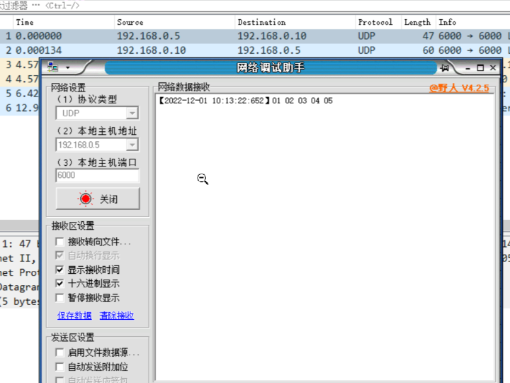
The final test results are shown in the figure below, including the wireshark packet capture results.

5 summary
The UDP communication of W5500 is not difficult, as long as the initialization is correct, and then read and write the socket register correctly when sending and receiving, then there is no difficulty. You still need to read the manual several times. The blogger downloads the Chinese manual from the official website, W5500 official website (Manuals, reference circuits, driver firmware, routines, etc.) , complete codes and projects are placed in the comment area.
After completing the UDP loopback test, the blogger also tried to perform the TCP test verification. W5500 was used as the client, but after the configuration was completed, it was found that W5500 did not send ARP packets.
————————————————
版权声明:本文为CSDN博主「萧长生」的原创文章,遵循CC 4.0 BY-SA版权协议,转载请附上原文出处链接及本声明。
原文链接:https://blog.csdn.net/changshengxiao/article/details/128124140