
Application example: Siemens S7-200 SMART compatible system (based on W5500 module)
Based on the STM32F103RCT6 core board, Add one TCP/IP communication (W5500), an S7-200 SMART compatible system is added.


WIZnet - W5500
x 1
Basic Information
Based on the STM32F103RCT6 core board, on the basis of the minimum system, an S7-200 SMART compatible system is added. Add one TCP/IP communication port, and the TCP/IP communication port is mounted with PPI protocol. Add one RS485 communication port, and the RS485 communication port is mounted with PPI protocol. Open the software STEP 7-MicroWIN SMART on the computer, and try to connect compatible systems via Ethernet and USB/PPI multi-host cables respectively.
video download
No
Experimental hardware
STM32F103RCT6 core board (1 piece) [ purchase ] :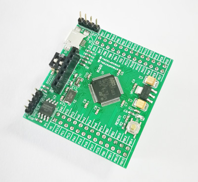
CH340E communication board (1 piece) [ Purchase ] :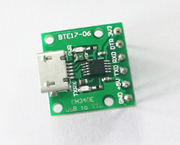
Micro-USB communication cable (1 piece) [ Purchase ] :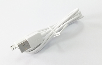
W5500 Ethernet communication module (1 piece) [ Purchase ] :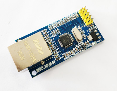
TTL to RS485 communication board (1 piece) [ Purchase ] :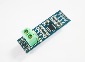
USB/PPI multi-host cable (1 piece)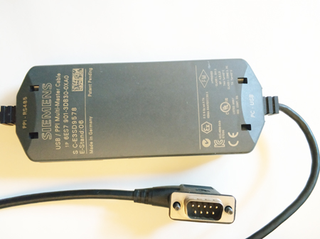
circuit reference
- The CH340E communication board is connected to the computer through the Micro-USB communication cable.
- CH340E communication board connected to STM32F103xC core board
| CH340E communication board | GND | ---- | GND | P4 terminal | STM32F103xC core board |
| +5V | ---- | 5V | |||
| TXD | ---- | RX | |||
| RXD | ---- | TX |
- W5500 Ethernet communication module connected to STM32F103xC core board
| W5500 Ethernet Communication Module | 5V | ---- | V5 | P1 terminal | STM32F103xC core board |
| GND | ---- | GND | |||
| SCS | ---- | PA7 | |||
| RST | ---- | PA6 | |||
| SCLK | ---- | PB3 | P2 terminal | ||
| MOSI | ---- | PB5 | |||
| MISO | ---- | PB4 |
- The W5500 Ethernet communication module is connected to the computer through a network cable (through a router or directly)
- The TTL to RS485 communication board is connected to the STM32F103xC core board
| TTL to RS485 communication board | VCC | ---- | V5 | STM32F103xC core board |
| GND | ---- | GND | ||
| DI | ---- | PC10 | ||
| DE, RE | ---- | PA8 | ||
| RO | ---- | PC11 |
- Connect the USB end of the USB/PPI multi-host cable to the computer
- USB/PPI multi-master cable connected to TTL to RS485 communication board
| USB/PPI multi-host cable | DB9.8 | ---- | A | TTL to RS485 communication board |
| DB9.3 | ---- | B |
Picture is not available
Key Configuration Notes
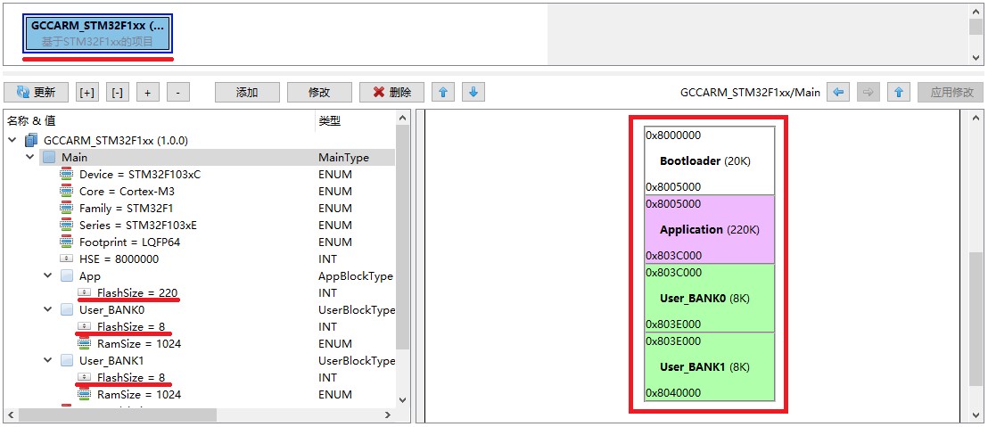
smallest system
Because the FLASH space required by the system firmware is relatively large, and the external FLASH is used to store the Siemens ladder diagram, the user space BANK0 and BANK1 are reduced to 8K here. The extra space is allocated for use by the system firmware.
NvM data storage
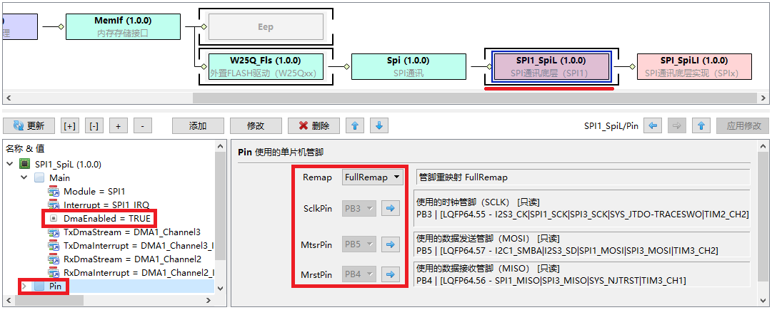
The Siemens ladder diagram is stored in the external FLASH, and the Sx200_Ecc module needs to read and save the data through the NvM interface. Here, the NvM blueprint needs to be added first. In the blueprint, add NvM module, MemIf module, W25Q_Fls module, Spi module, SPI1_SpiL module, SPI_SpiLI module.

Select the module SPI1_SpiL in the blueprint, and confirm that the pins for SPI communication are PB3, PB5, and PB4. Because this SPI data volume is relatively large (not only connected to the FLASH chip, but also negatively connected to the network chip W5500), it is recommended to turn on the DMA data transfer function to reduce the interrupt processing load of the CPU.
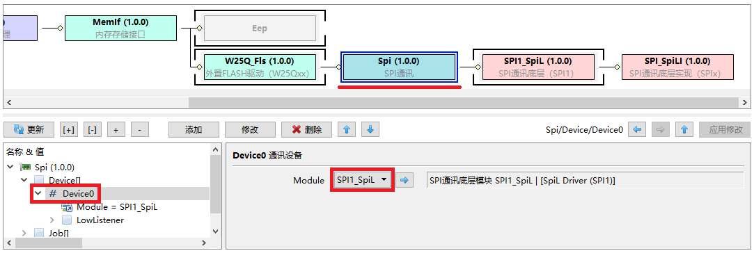
Select the module Spi in the blueprint, add the device Devicke0 under the Device node, and call the hardware module SPI1_SpiL.
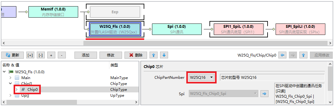
Select the module W25Q_Fls in the blueprint, and add the memory chip Chip0 under the configuration node Chip. The selected chip model is W25Q16.
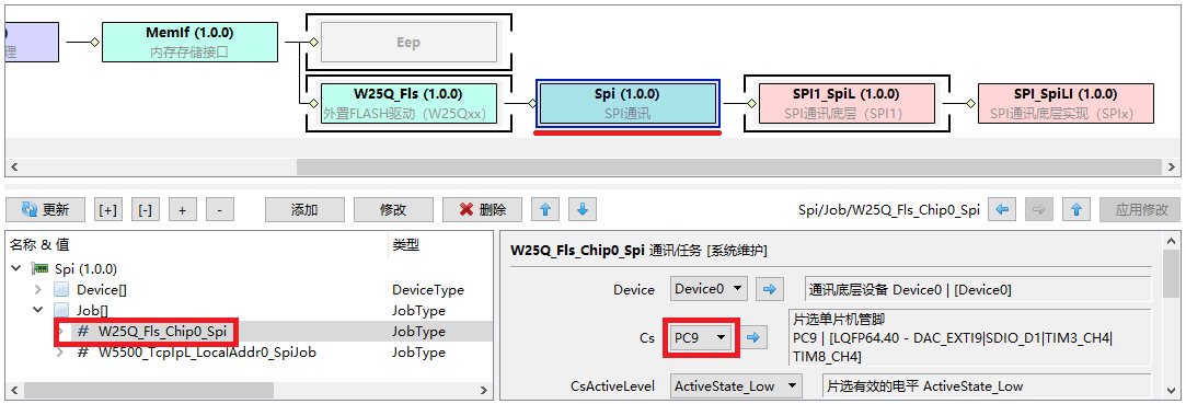
Select the module Spi in the blueprint, and view the communication task automatically added by the system under the configuration node Job: W25Q_Fls_Chip0_Spi. Confirm that the communication device is Device0, and the chip select pin is PC9.
PPI communication protocol (based on RS485)
Here you need to add the PPI communication blueprint first. In the blueprint, add the PPI module and the Rs485_PPIL module. Minimal systems usually use USART1 to deploy the Modbus protocol, here we add USART3 to deploy the PPI protocol.
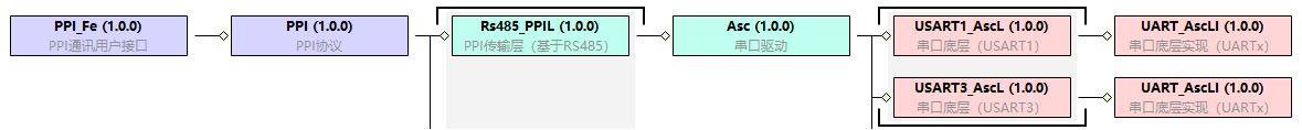
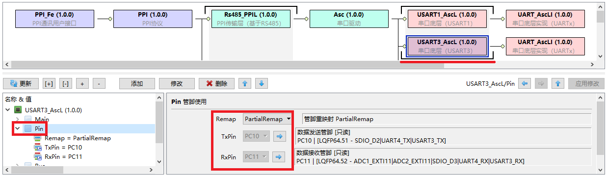
Select the module USART3_AscL in the blueprint, and confirm that the communication pins of USART3 are PC10 and PC11 respectively.
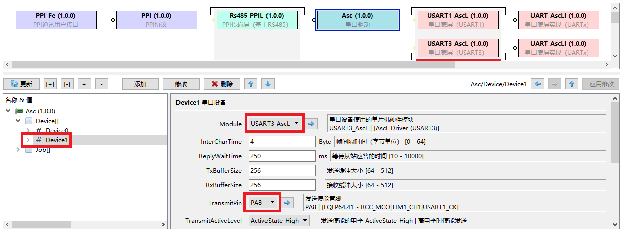
Select the module Asc in the blueprint, add the device Device1 under the Device node, and call the hardware module USART3_AscL. Here we have configured an RS485 transceiver enable pin PA8, which is effective at high and low levels.
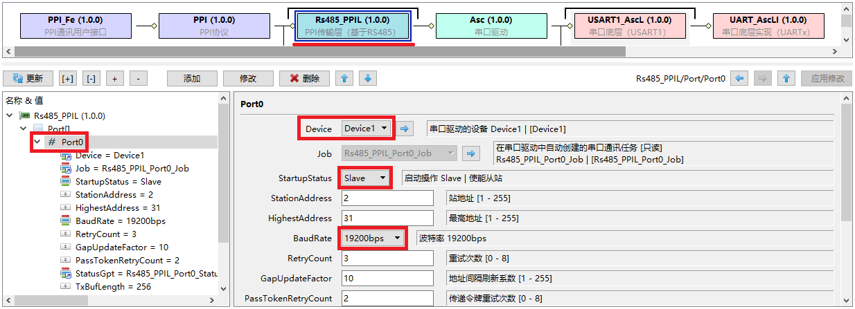
Select the module Rs485_PPIL in the blueprint, add the port Port0 under the Port node, and call the device Device1 managed by Asc. The default working mode is Slave and the baud rate is 19200bps.
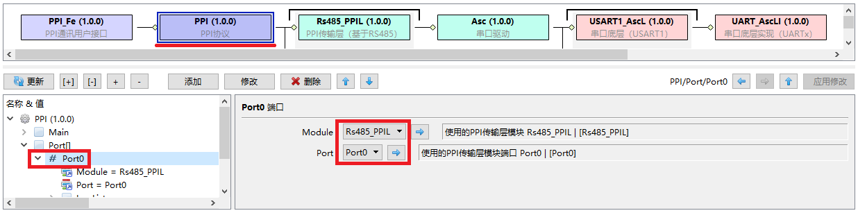
Select the module PPI in the blueprint, add the port Port0 under the Port node, and call the port Port0 of the transmission module Rs485_PPIL.
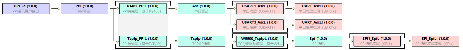
PPI communication protocol (based on W5500)
On the basis of the original PPI communication blueprint, add TcpIp_PPIL module, TcpIp module, and W5500_TcpIpL module. The Spi module has been added when configuring NvM and will appear automatically.
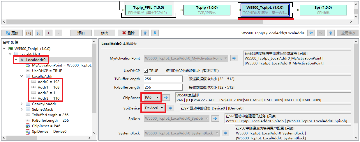
Select the module W5500_TcpIpL in the blueprint, and add the network card LocalAddr0 under the LocalAddr node. The network card uses the SPI device Device0 for communication, the reset pin is PA6, and the default IP address is 192.168.1.110.
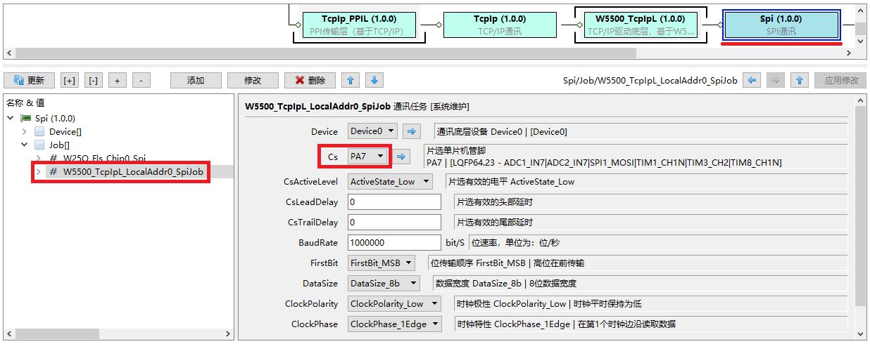
Select the module Spi in the blueprint, and view the communication tasks automatically added by the system under the configuration node Job: W5500_TcpIpL_LocalAddr0_SpiJob. Confirm that the communication device is Device0, and the chip select pin is PA7. The communication parameters of SPI use default values.
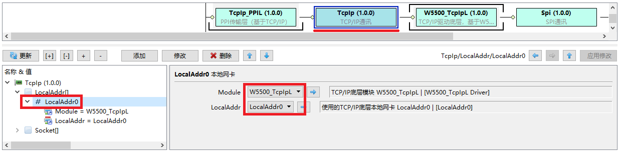
Select the module TcpIp in the blueprint, add the network card LocalAddr0 under the configuration node LocalAddr, and call the LocalAddr0 of the hardware module W5500_TcpIpL.
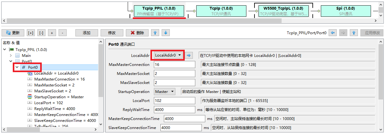
Select the module TcpIp_PPIL in the blueprint, and add the port Port0 under the Port node. The network card used is LocalAddr0 managed by the IcpIp module. Other parameters can use the default values.
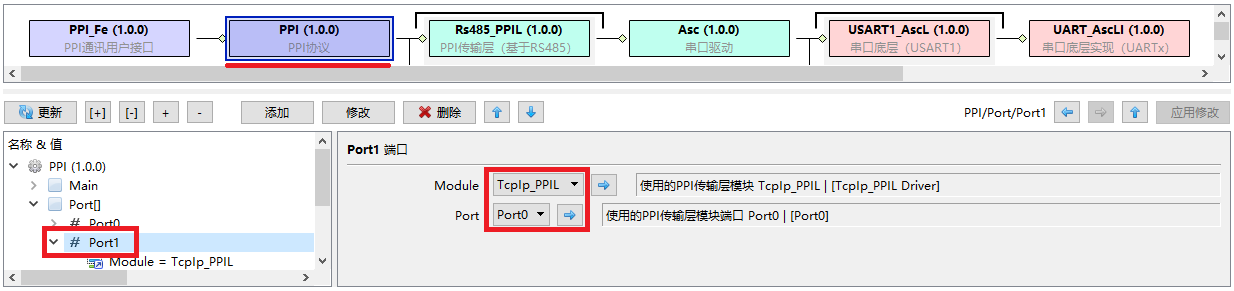
Select the module PPI in the blueprint, add the port Port1 under the Port node, and call the port Port0 of the transmission module TcpIp_PPIL.
S7x200 Siemens Compatible Extended Control
Here you need to add the S7x200 blueprint first:

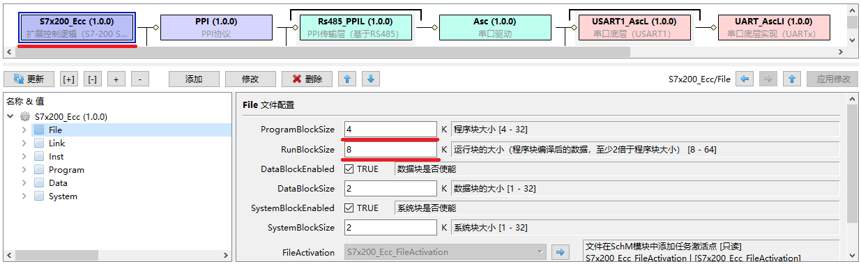
Select the module S7x200_Ecc in the blueprint, because the memory of STM32F1 is relatively small, you can mainly modify the space allocation of the next blocks. Here the program block is set to 4K and the run block is set to 8K.
Experimental procedure
Upload the configuration to the server and download the firmware to the STM32F103xC core board.
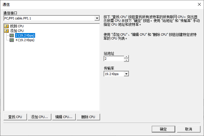
Open the software STEP 7-MicroWIN SMART, select the communication method as: PC/PPI cable.PPI, manually add PLC: 2 (19.2Kbp) or get it by scanning.
Write a simple program in the software STEP 7-MicroWIN SMART and download the program to the PLC to run through the USB/PPI multi-master cable. Enter the monitoring mode to monitor the operation of the program.
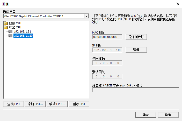
Select the communication method: Killer E2400 Gigabit Ethernet Controller.TCPIP.1 (the name of the network card connecting the computer to the PLC, different computers have different names), manually add the PLC: 192.168.1.110 (currently the PLC does not support the scan function).
Write a simple program in the software STEP 7-MicroWIN SMART and download it to the PLC to run through the network cable. Enter the monitoring mode to monitor the operation of the program.
Instruction description
none
Related Downloads
- Configurator: F1_24_Ecc_S7x200_Rs485_W5500.bin