A smart farm system using W5300-TOE-Shield, STM32 Nucleo, temperature/humidity, light, and soil moisture sensors to supply moisture in farm
COMPONENTSHardware components
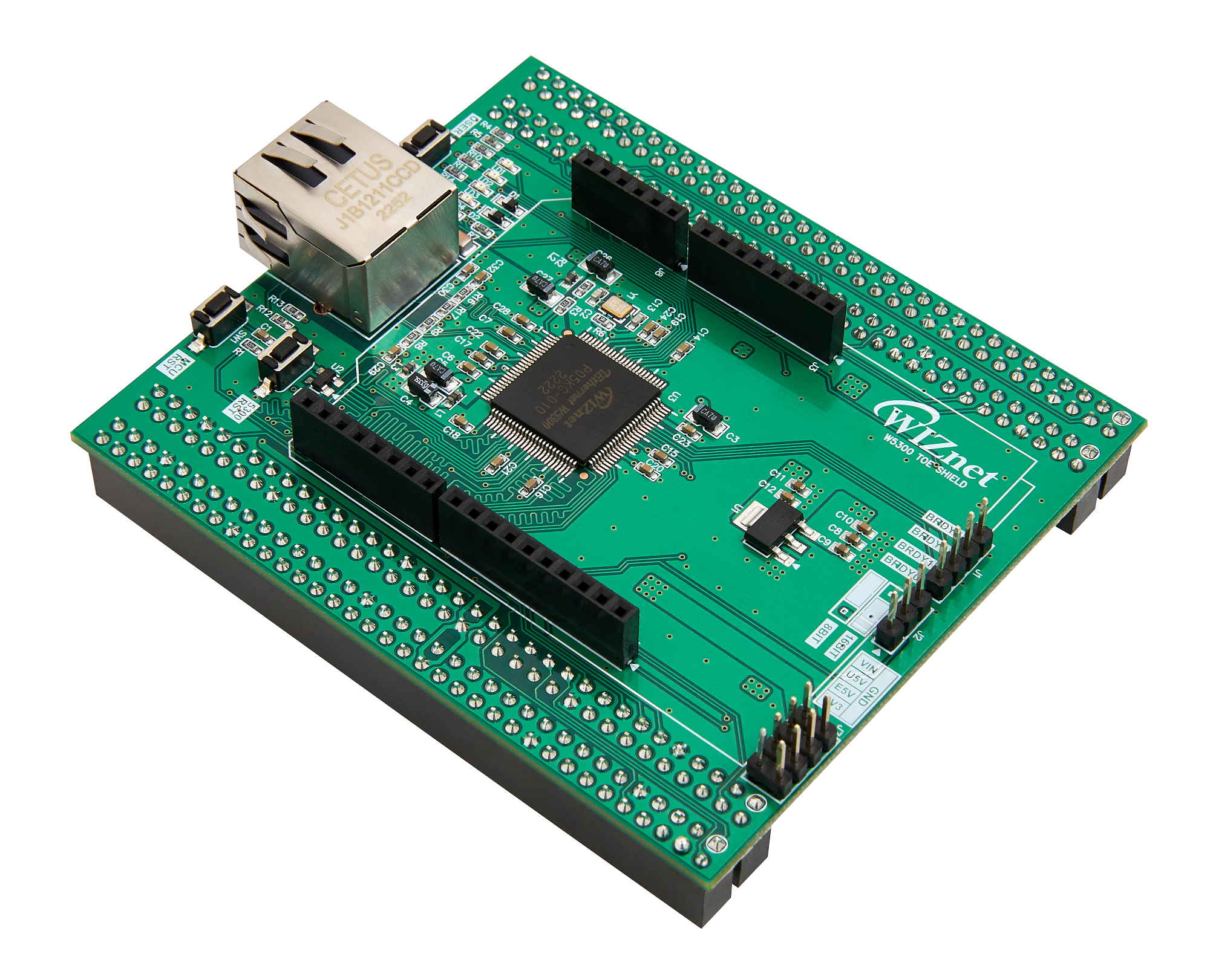
WIZnet - W5300-TOE-Shield
x 1
W5300-TOE-Shield
DFRobot - Gravity: DHT11 Temperature Humidity Sensor For Arduino
x 1
Humidity and Temperature sensor
Software Apps and online services
Arduino - Arduino IDE
x 1
IDE
WIZnet - WIZnet io Library
x 1
Wiznet arduino library
PROJECT DESCRIPTION
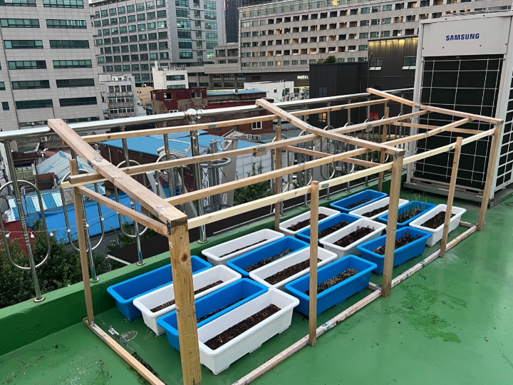
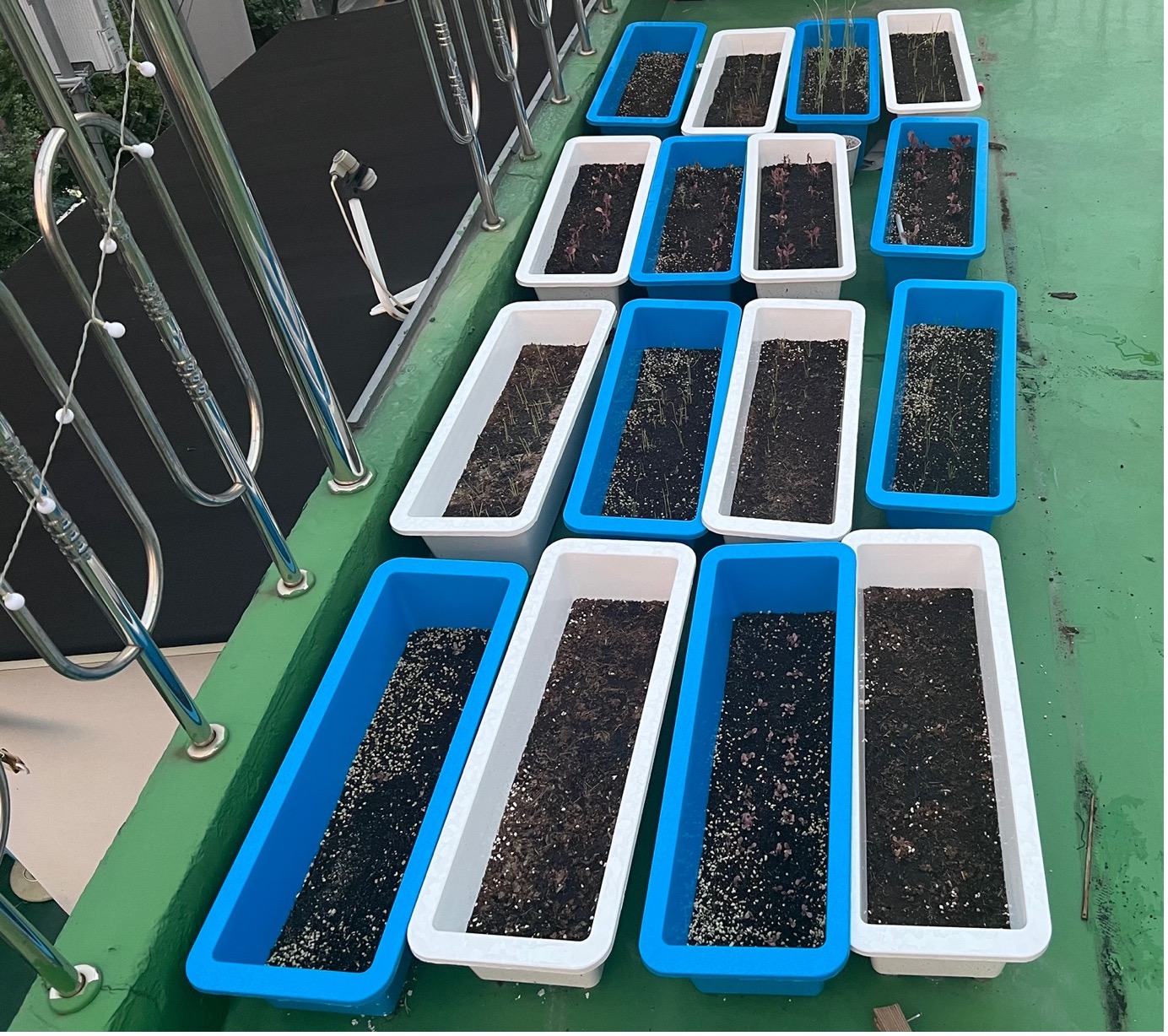
Story Around June of this year, I started cultivating a small garden with lettuce, green onions, and chives in my personal office space. After sowing the seeds, I diligently watered them daily with utmost care. However, as time passed, the weather grew hotter, and moisture became scarce. Due to a busy work schedule, managing the garden became challenging. Visiting the office every 3-4 days, I frequently observed the pots drying up, with soil cracking from dehydration.
Although I aimed to harvest within 50 days, by August, none of the crops had grown properly. With a desire for ordinary office workers like myself to experience the simple joy of cultivating and consuming homegrown produce, I constructed an IoT-based smart farm system using Raspberry Pi and Wiznet's TOE Shield.
The system employs ambient temperature, humidity, and soil moisture sensors to visualize the smart farm's environment through a web server, enabling real-time monitoring. For the soil moisture sensor, an automatic design activates the water pump motor to irrigate when the set soil moisture threshold is surpassed.
In the future, I plan to install a camera for real-time capturing of the smart farm's interior, offering a small healing escape within the urban hustle.
List of Items Used for System Setup Temperature and Humidity Sensor – DHT11 Light Sensor - CDS LED - ongoing Analog soil sensor Watering Pump Greenhouse Frame – wood, pieces Vinyl Sheeting Web Server – ongoing Ethernet Stm32 Nucleo 144/board – MCU board W5300-TOE Shield – TCP/IP offload Ethernet Relay module
Operation Scenario and Function Explanation I had three main conditions in mind for automating the irrigation process. Firstly, when the ambient temperature is too high, it can potentially harm the crops, so the goal is to lower the temperature. Secondly, if the soil becomes excessively dry, it can hinder the growth of plants, so maintaining soil moisture above a certain level is crucial. Additionally, to add a touch of fun to the sophisticated smart farm system, I incorporated a welcome irrigation system that activates when users access the smart farm. Furthermore, the goal was to implement the fundamental aspect of the smart farm system, a remote monitoring system.
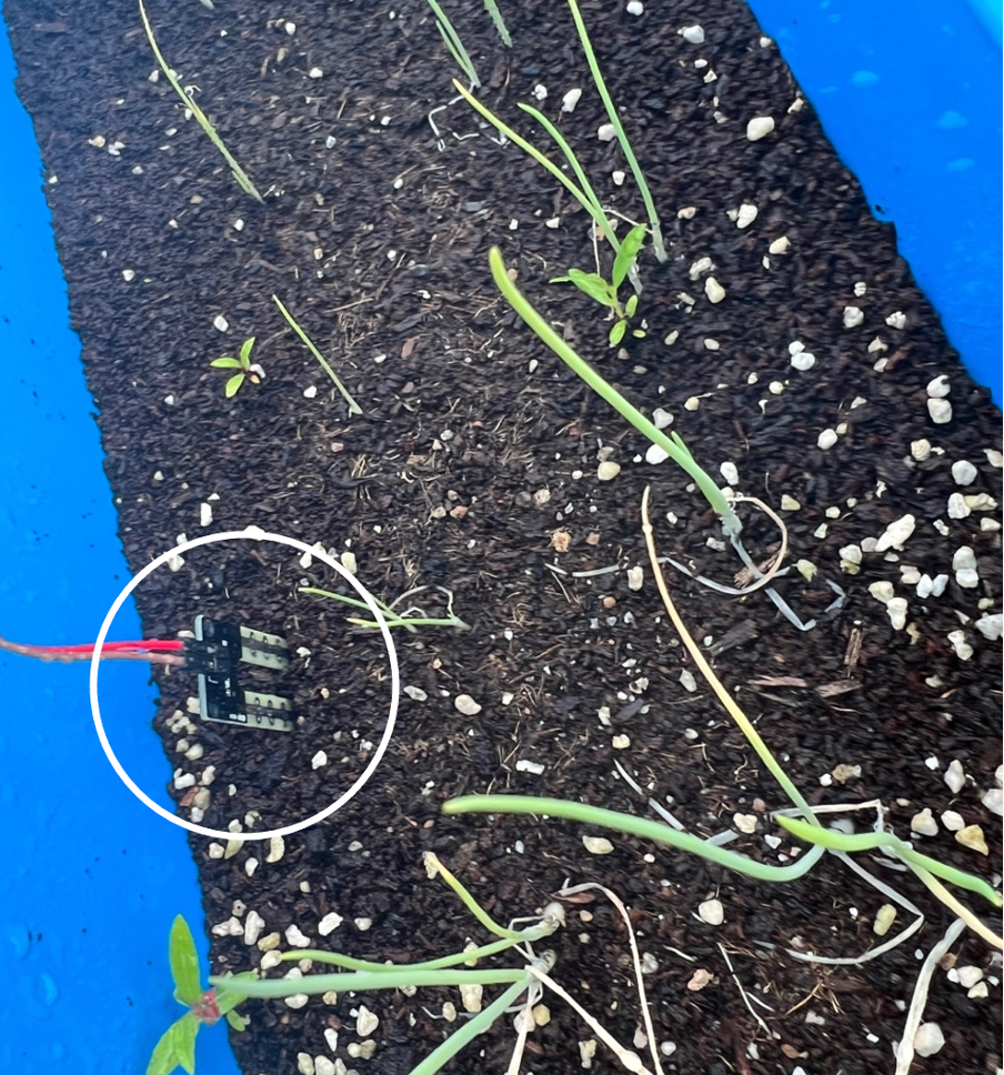
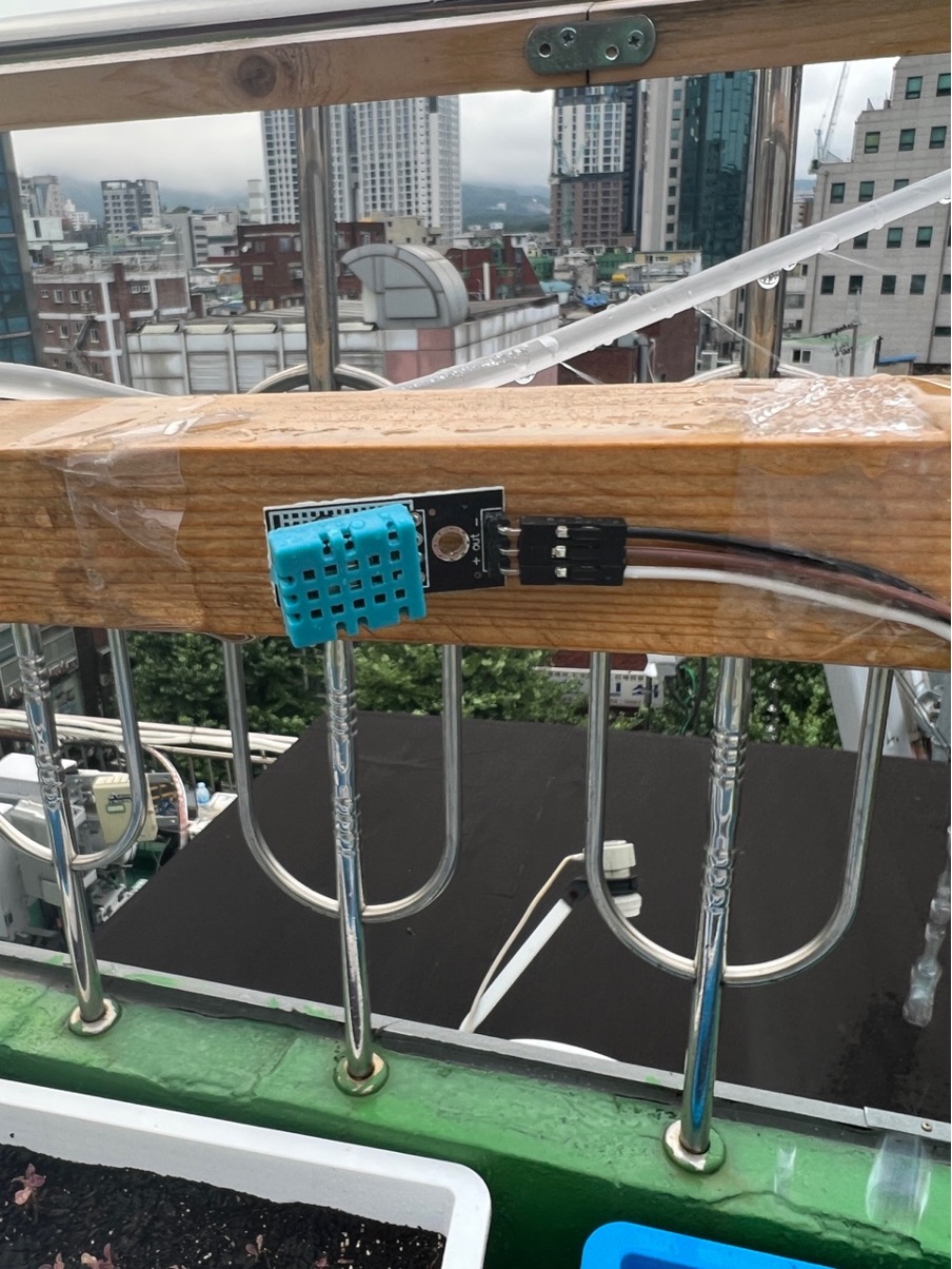
Monitoring Real-time measurement of soil moisture, ambient temperature and humidity, and the required light intensity for plants is provided. Soil Moisture Measurement: Soil moisture detection sensor is plugged into the pot to measure (0 to 1023, higher value indicates higher moisture, 1023 is extremely dry, using analogRead()). Ambient Temperature and Humidity Measurement: Placing the DHT11 (temperature and humidity sensor) on top of the pot for measurement (sensor capable of measuring temperature and humidity, using digitalRead()).
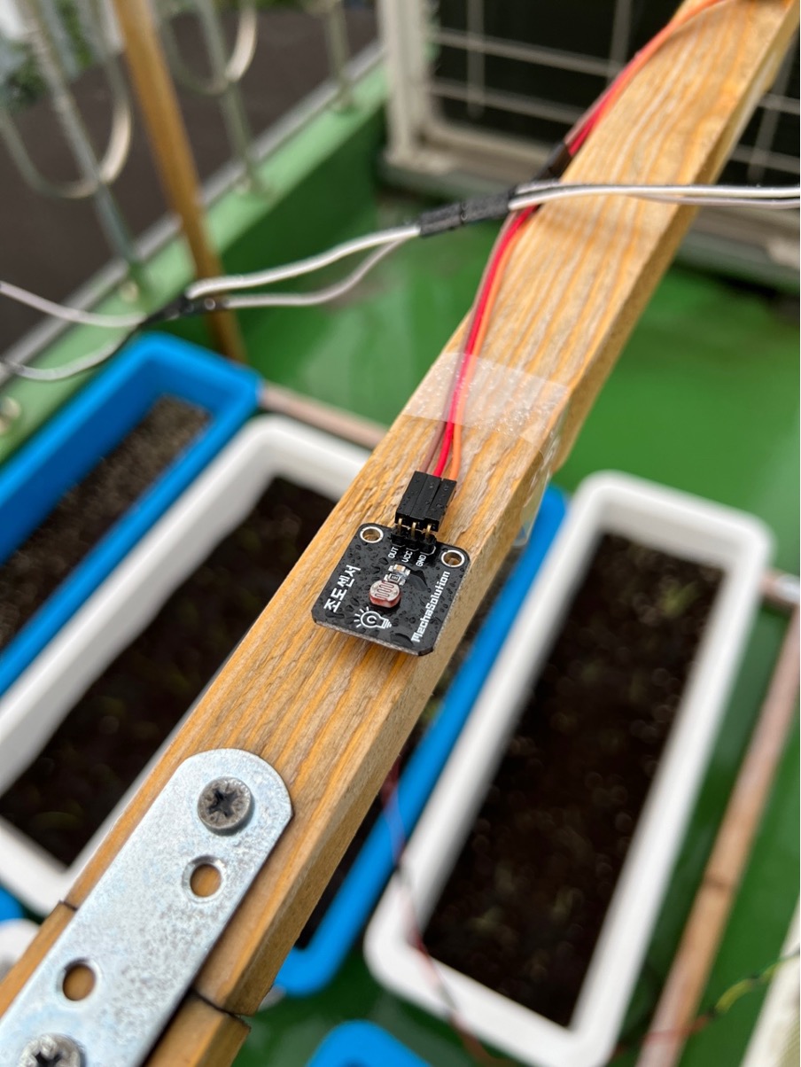
Light Intensity Measurement: Measurement using a CDS sensor (ranging from 0 to 1023, higher values indicate brighter light, 1023 represents extremely dark conditions, using analogRead()).
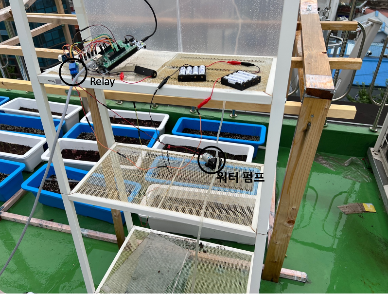
Control Devices Water Pump: Power control for the water pump is achieved using a relay (electronic switch). The water pump's specifications include using eight 1.5V batteries to provide 12V power. The relay's specification indicates a 5V operating voltage. The output signal from the GPIO pins of the STM32 board and the W5300 TOE Shield is 3.3V, but since the signal output required by the relay module is 5V, voltage amplification was necessary. While circuit configurations involving transistors were possible, I explored an alternative method by directly connecting a 15V battery in series with the GPIO pin to raise the signal voltage itself. This approach was attempted due to the unavailability of desired components. Ultimately, it was confirmed that this workaround functions correctly. When faced with similar circumstances, other makers might find it helpful to consider such a bypass method.
The execution codes for each function https://github.com/hitem8029/smartfarm_w5300
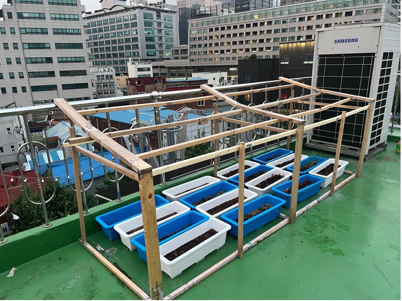
Structures and Equipment for Smart Farming To construct the greenhouse for the smart farm, a framework was built using wooden beams, which were connected using nails and brackets. The vinyl was designed to be detachable, and it is currently in a disassembled state.