


KinCony MT4 ESP32-S3 4 Channel DC Motor Controller
KinCony MT4 ESP32-S3 4 Channel DC Motor Controller

WIZnet - W5500
x 1

Summary
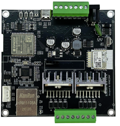
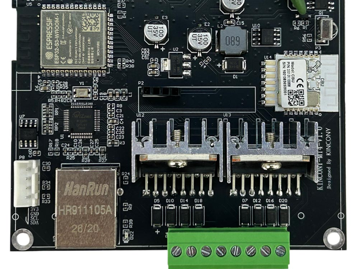
The KinCony MT4 is an ESP32-S3-based controller designed to operate four bidirectional DC motors in automation, robotics, and actuator systems. Its L298N motor-driver stages handle direction and speed control, while the onboard WIZnet W5500 provides wired Ethernet connectivity for TCP commands, monitoring, and integration with local control systems.
What the Project Does
The MT4 combines an ESP32-S3-WROOM-1 N16R8 module with four independent L298N motor-control channels. Each channel exposes two direction signals and one PWM signal, allowing firmware to command forward rotation, reverse rotation, variable speed, and stop states. KinCony rates each motor output for loads up to 2 A and specifies a 12 V DC board supply.
The controller is intended for applications such as motorized curtains, roller blinds, window openers, electric valves, linear actuators, automatic doors, and small robotic mechanisms. In addition to motor outputs, the board includes RS485, Wi-Fi, Bluetooth, a Tuya module, 433 MHz and infrared receivers, I²C expansion, two general-purpose inputs, USB-C, and Ethernet through the W5500.
A typical wired-control data path is:
TCP client → Ethernet cable → W5500 → SPI → ESP32-S3 → direction/PWM GPIO → L298N → DC motor
The ESP32-S3 interprets incoming commands and updates the motor-control pins. The W5500 handles the Ethernet interface and hardware TCP/IP processing, keeping network transport separate from the time-sensitive PWM and direction-control logic.
Where WIZnet Fits
The MT4 uses a WIZnet W5500 connected to the ESP32-S3 through SPI. KinCony assigns GPIO42 to SPI clock, GPIO43 to MOSI, GPIO44 to MISO, and GPIO41 to chip select. GPIO1 resets the W5500, while GPIO2 receives its interrupt output.
The W5500 provides hardware TCP/IP offload, eight hardware sockets, and 32 KB of internal transmit/receive memory. In this controller, its practical role is to maintain wired network communication while the ESP32-S3 remains responsible for command parsing, automation rules, PWM generation, sensor handling, and RS485 communication.
This separation is useful in motor-control installations because Ethernet traffic does not require the ESP32-S3 to run a complete software TCP/IP stack for every packet. A physical Ethernet link also avoids the changing signal quality and channel contention associated with Wi-Fi. It does not make the motor loop inherently real-time, but it provides a more stable transport for fixed equipment, DIN-rail panels, and local automation networks.
KinCony’s published Arduino example configures the board as a TCP server on port 4196. The example receives characters from a network client and echoes them back, demonstrating that the W5500 can act as the transport layer for a future motor-command protocol.
Implementation Notes
W5500 initialization
Source: Ethernet-W5500.ino, published in KinCony’s MT4 Arduino example forum thread.
SPI.begin(W5500_CLK_PIN, W5500_MISO_PIN, W5500_MOSI_PIN);
Ethernet.init(W5500_CS_PIN);
Ethernet.begin(mac, ip, dns, gateway, subnet);

EthernetServer server(4196);
server.begin();
The first call maps the ESP32-S3 SPI peripheral to the MT4’s W5500 wiring. Ethernet.init() selects GPIO41 as the W5500 chip-select signal, and Ethernet.begin() applies the example’s static network configuration. The server then listens on TCP port 4196 for incoming connections.
The example also performs a hardware reset before starting SPI:
digitalWrite(W5500_RST_PIN, LOW);
delay(100);
digitalWrite(W5500_RST_PIN, HIGH);
This reset sequence places the W5500 in a known state after power-up or firmware restart. It is particularly important when the ESP32-S3 resets without removing power from the Ethernet controller.
Motor direction and speed control
Source: motor.ino, published in KinCony’s L298N motor-control example.
AlashMotorControlLite motor(DIR_DIR_PWM, 39, 46, 9);

motor.setSpeed(100);
motor.setSpeed(0);
motor.setSpeed(-100);
GPIO39 and GPIO46 select the first motor’s direction, while GPIO9 supplies its PWM signal. Positive and negative values command opposite directions, and zero stops the motor. KinCony assigns equivalent direction and PWM pins to the other three channels.
The published Ethernet and motor demonstrations are separate examples. A complete networked motor controller must combine them with an explicit command format, validation, timeout handling, and safe-stop behavior. For example, a TCP message could identify the channel, direction, and requested PWM value, but the production protocol should reject malformed or out-of-range commands before changing an output.
Practical Tips / Pitfalls
- Use the documented SPI pins. The onboard W5500 is mapped to GPIO42, GPIO43, GPIO44, and GPIO41. Generic ESP32 Ethernet examples may assume different default SPI pins.
- Reset the W5500 during startup. Toggle GPIO1 low and then high before Ethernet initialization so MCU-only resets do not leave the network controller in an undefined state.
- Add a communication watchdog. Stop the affected motor when the TCP client disconnects or when valid commands have not arrived within a defined interval.
- Do not treat the 2 A rating as unlimited operating margin. Check motor startup and stall current, driver temperature, enclosure airflow, wiring size, and supply capacity. DC motors can draw several times their running current during startup or mechanical blockage.
- Avoid immediate direction reversal. Command zero speed first, allow the motor to decelerate, and then reverse direction. This reduces current spikes and mechanical stress.
- Choose DHCP or static addressing deliberately. Static addressing simplifies PLC and fixed-panel integration. DHCP is easier to deploy but should be combined with reservations or service discovery when clients must reliably locate the controller.
- Separate noisy motor wiring from Ethernet and logic wiring. Use short motor-current paths, adequate grounding, suitable suppression at inductive loads, and physical separation from the Ethernet cable to reduce resets and packet errors.
FAQ
Why use the W5500 on the KinCony MT4?
The W5500 implements TCP/IP processing and socket buffering in hardware. That reduces the networking work performed by the ESP32-S3 and leaves more predictable processing capacity for PWM generation, command validation, RS485 handling, and automation logic. Wired Ethernet is also suitable for fixed installations where stable connectivity is more important than wireless placement flexibility.
How does the W5500 connect to the ESP32-S3?
It uses SPI. On the MT4, GPIO42 is SCK, GPIO43 is MOSI, GPIO44 is MISO, and GPIO41 is chip select. GPIO1 controls W5500 reset, and GPIO2 is connected to its interrupt output. These assignments must be passed to the SPI and Ethernet libraries rather than relying on default ESP32-S3 pin mappings.
What does the W5500 do in this motor-control project?
It transports commands and status information between the MT4 and a local TCP client, automation server, HMI, or gateway. The W5500 does not drive the motors directly. The ESP32-S3 receives network data through the W5500, validates the requested operation, and controls the L298N direction and PWM inputs.
Can beginners build the Ethernet-controlled motor application?
A developer familiar with Arduino GPIO, PWM, SPI, and basic IP addressing can reproduce the individual KinCony examples. Combining them safely is an intermediate task because the firmware must also handle command framing, disconnects, motor timeouts, current limits, and emergency-stop behavior. Testing should begin without a mechanical load and with a current-limited supply.
How does the W5500 compare with Wi-Fi for this controller?
Wi-Fi requires no network cable and is convenient for mobile or difficult-to-wire installations. The W5500 is preferable for fixed control panels when consistent link availability, reduced exposure to radio interference, and straightforward LAN integration are priorities. Wi-Fi remains useful for commissioning or consumer automation, while Ethernet is generally easier to supervise in permanent industrial and building-control installations.