
How to build a wired TLS WebSocket home theater controller with WIZnet W5500 on ESP32 (ESP-IDF)?
This repository implements an ESP32-based home theater controller that relies on a hardwired Ethernet link (WIZnet W5500 over SPI)


WIZnet - W5500
x 1
What the Project Does
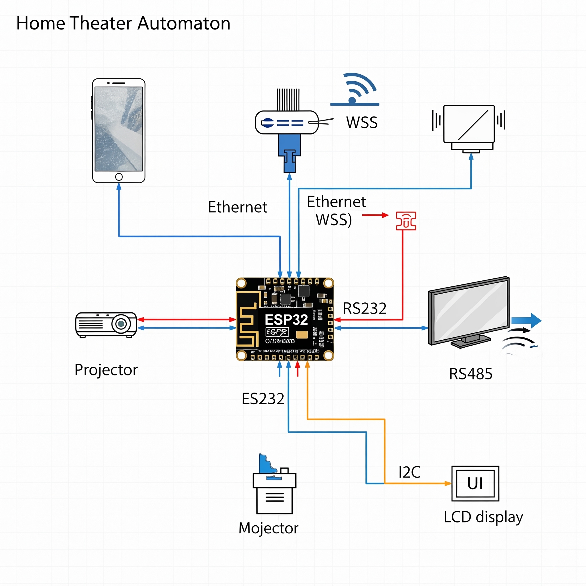
At a system level, the controller sits on your LAN and provides a secure control plane for home theater actions (for example, raising/lowering a projection screen) while directly driving A/V hardware over serial buses. The project describes:
- Ethernet-first connectivity: the ESP32 is intended to run on wired Ethernet, not Wi-Fi.
- TLS control interface: the firmware uses ESP-IDF’s HTTPS server support and WebSockets for real-time commands, with certificates/keys provisioned onto the device storage.
- Serial device integration: RS232 is used for an Optoma projector, and RS485 for a motorized projection screen; network commands are translated into the corresponding serial frames.
- Provisioning workflow: a desktop tool generates certificates/keys and produces a QR code for quick client pairing, then flashes firmware + a LittleFS partition that contains those generated assets.
Where WIZnet Fits
This design uses WIZnet W5500 as the wired Ethernet interface, connected to the ESP32 via SPI. In the ESP-IDF ecosystem, W5500 is typically driven as an SPI Ethernet MAC/PHY device (with the TCP/IP stack handled by the ESP32’s networking stack), while still benefiting from W5500’s integrated Ethernet interface and buffering characteristics.
In this project, W5500’s role is very pragmatic:
- Deterministic, low-latency control path: WebSockets are used specifically to avoid interactive lag compared to REST-only approaches, and the wired link removes RF variability in an equipment rack.
- Cabinet-friendly reliability: the hardware notes call out power/decoupling changes (e.g., a larger electrolytic capacitor on the Ethernet module) to eliminate link drops—exactly the kind of issue that shows up near switching supplies, motors, and long cable runs.
- Clear electrical integration: the firmware fixes a specific SPI host, pinout, interrupt, and reset GPIOs for W5500, making the networking hardware repeatable instead of “module-of-the-week.”
Implementation Notes
Below are two concrete code-level anchors showing how W5500 Ethernet and the TLS server are wired into the firmware.
A. W5500 is instantiated through ESP-IDF’s Ethernet driver APIs (SPI MAC/PHY path)
File: esp32_firmware/components/eth_w5500/eth_w5500.c
Why it matters: this is the point where the firmware commits to W5500 specifically (not generic Wi-Fi or an RMII PHY). It builds the Ethernet driver around W5500’s SPI configuration, including a dedicated interrupt GPIO and hardware reset line.
B. The W5500 wiring contract is made explicit (pins + SPI clock + link-wait behavior)
File: esp32_firmware/components/eth_w5500/include/eth_w5500.h
Why it matters: networking problems on SPI Ethernet are often “just wiring” (wrong CS, missing INT, marginal reset, too-fast SPI for your layout). This header makes the hardware assumptions audit-friendly and easy to port to a custom PCB.
How the secure network service comes up (IP-event driven TLS server start/stop)
File: esp32_firmware/components/https_server/https_server.c
- The server loads PEM assets from
/storage/..., starts when Ethernet gets an IP, and stops when the Ethernet link drops. - The WebSocket dispatch path uses a queue + a dedicated task, and it enforces a “single active client” policy (new client can kick the old socket). That keeps UI latency predictable and avoids multi-client state drift in a controller that’s meant to feel like a remote.
Practical Tips / Pitfalls
- Treat W5500 power like an RF/EMI problem: if your link is flaky, start with bulk + ceramic decoupling near the module; this project explicitly upsized the Ethernet module electrolytic to address drops.
- Don’t ignore INT and RST: the firmware expects a working interrupt GPIO and a hardware reset GPIO—wire both, even on prototypes.
- Be intentional about DHCP vs static IP: the driver code applies a static IP only when
ipis non-empty; otherwise it leaves DHCP as the default behavior. Plan your provisioning UI accordingly. - Certificates live on-device: TLS assets are read from filesystem paths (e.g.,
/storage/cacert.pem,/storage/prvtkey.pem), so your flashing/provisioning step must generate and place them correctly. - Expect “one controller, one active UI” semantics: the WebSocket dispatcher is written to keep only one active socket; if you need multi-client dashboards, you’ll need a different session model.
- SPI clock is part of your signal integrity budget: this firmware sets SPI to 16 MHz; if you change wiring length, grounding, or board layout, validate link stability before pushing the clock higher.
FAQ
Q1) Why use WIZnet W5500 here instead of Wi-Fi?
Because the controller is built for “remote-control feel” (low jitter) and equipment-rack reliability. The project explicitly chooses WebSockets for real-time control and calls out hardware measures to eliminate Ethernet link drops—signals that stability matters more than convenience. Wired Ethernet also avoids RF dead zones behind A/V gear.
Q2) How does W5500 connect to the ESP32 in this project?
Over SPI using a fixed pin mapping: SCLK=GPIO18, MOSI=GPIO23, MISO=GPIO19, CS=GPIO5, INT=GPIO4, and a dedicated reset on GPIO32, with SPI3_HOST selected and a 16 MHz clock.
Q3) What role does W5500 play in this firmware’s networking stack?
It provides the wired Ethernet interface that the ESP32 attaches to an esp_netif instance. The firmware creates W5500 MAC/PHY objects via esp_eth_mac_new_w5500(...) and esp_eth_phy_new_w5500(...), then uses Ethernet/IP events (e.g., “got IP”) to bring the TLS server online.
Q4) Can beginners follow this, or is it an advanced networking build?
It’s approachable if you already have basic ESP-IDF familiarity and you’re comfortable wiring SPI modules. The “gotchas” are mostly practical: correct INT/RST wiring, stable power/decoupling, and understanding that TLS assets must be provisioned into the filesystem before the server can start.
Q5) What’s the trade-off versus an ESP32 + LwIP-only (no W5500) approach or a different Ethernet option?
Using W5500 over SPI is mechanically simple and keeps your Ethernet interface modular, but you must budget SPI signal integrity and throughput (and treat power/grounding seriously). An RMII PHY (e.g., LAN8720-class designs) can offer higher throughput and avoids SPI timing issues, but it complicates PCB routing and pin usage. For this project’s needs (control commands + status over TLS/WebSockets), the SPI Ethernet path is a sensible fit.