
Android App controlling W5100S-EVB-Pico 2 as IOT device
A easy-to-implement project that allows communication between your desired app with the board using local network or cloud service.
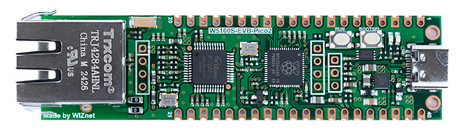
WIZnet - W5100S-EVB-Pico2
x 1
Story
Introduction
Today I will be showing you how to create your own app that links to your W5100S-EVB-Pico 2 and use it as a home control system to transmit data locally or through IOT platforms such as Adafruit. This will be a long project as I will be explaining on how I build my App, how I set up my http server on CircuitPython and how to make these device communicate with each other, and also to Adafruit.
As I am a beginner in writing Android Apps, I have used ChatGPT to help me make my first Android app. Bascially, I use ChatGPT to debug my file, create functions based on my need, and create pictures for the app to display with.
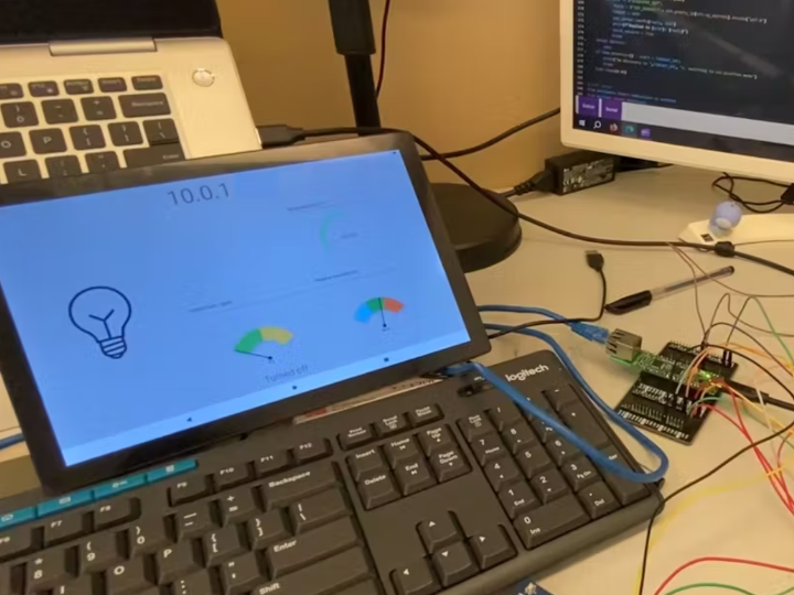
Here is a short demo on how the whole app functions.
🔧Set up
For the hardwares needed in this project, I will use the SFA30 that uses UART connection and outputs the current temperature (°C), relative humidity (%) and the Formaldehyde concentration (ppb), a light bulb for On and Off, and a speaker for playing sound if the Android device is connected locally to the Pico server.
In CircuitPython, you will need these libraries in order to work on this project.
1. adafruit_wiznet5k
2, adafruit_requests
3. adafruit_ticks
4. adafruit_connection_manager
5. adafruit_minimqtt
6. adafruit_httpserver
In Android Studio, I use Ktor as my http client, a simple-gauge-android library created by Gruzer on Github, and lifecycle for multitasking in the app. These libraries are all suggested by ChatGPT. In the AndroidManifest xml file, add these two lines inside the manifest brackets to read the current network status of the device and allowing the app to access the interenet.
<uses-permission android:name="android.permission.INTERNET" />
<uses-permission android:name="android.permission.ACCESS_NETWORK_STATE"/>
This is how I connected everything in my CircuitPython board.
_BvyUD4GsSU.jpg?auto=compress%2Cformat&w=740&h=555&fit=max)
After finish preparing our board for the project, we can now set the Adafruit IO interface.
This is my interface used for the program

The keys for each value are as follow.
Title Key
Connected to IOT Device online
Light light
Temperature temp
Humidity humid
Formaldehyde concentration conc
Next, save your AIO-username and your AIO-key to a secrets.py file under the lib folder. You can find the information by going to the yellow key located on the top-right of the page.
secrets = {
    'ssid' : 'something',
    'password' : 'your-password-here',
    'aio_username' : "YOUR_AIO_USERNAME",
    'aio_key' : 'YOUR_AIO_KEY'
}
The Android App Interface is as follow.

The IP address on top shows the local ip address of the IOT device. The three meter shows HCHO Concentration, Relative Humidity and the Temperature. Lastly, the light bulb serves as a button to turn the light on and off.
Now, we can go to the codes on my Android Device.
📲Kotlin Code on Android Device
I started by creating the app without the help of ChatGPT as I don't really get the syntax after generating the app and do not understand how to change the codes when I generated the app on ChatGPT o4-mini-high. Besides, as I recall, my generated app has a lot of error while compiling. So, I start by creating the app by my own but using guidance from ChatGPT.
I will explain my codes as I go through the codes starting from MainActivity.kt and explain my uses of ChatGPT in each case. You can check the imports from my Android Kotlin file posted on Github.
Here is some of the gradle files in addition to the base library of your empty activity.
// inside build.gradle

val ktor_version: String by project

dependencies{
    ...
    implementation("io.ktor:ktor-client-core:$ktor_version")
    implementation("io.ktor:ktor-client-cio:$ktor_version")
    implementation("io.ktor:ktor-client-content-negotiation:$ktor_version")
    implementation("io.ktor:ktor-serialization-kotlinx-json:$ktor_version")
    implementation("androidx.core:core-splashscreen:1.0.0")
    implementation("androidx.lifecycle:lifecycle-service:2.6.1")
    implementation("androidx.recyclerview:recyclerview:1.2.1")
    implementation("com.github.Gruzer:simple-gauge-android:0.3.1")
}
Before coding the project, we also need to include some extra permission to allow internet access and reading current network stuaus. Include these two lines in the AndroidManifest.xml file.
// Inside <manifest> ... </manifest> of AndroidManifest.xml

<uses-permission android:name="android.permission.INTERNET" />
<uses-permission android:name="android.permission.ACCESS_NETWORK_STATE"/>
Firstly, the Android app already help us defined the class of Main Acitivity that provide tempalte function of OnCreate and OnDestroy where we will be required to code inside. In this Main Activity class, I initialized these few variables by following guidance from ChatGPT.
MainActivity XML
private lateinit var binding: ActivityMainBinding
private val client = HttpClient(CIO) {
    install(ContentNegotiation) {
        json()
    }

    install(HttpTimeout){
        requestTimeoutMillis = 5000

        socketTimeoutMillis = 5000
    }
}
private var discoveryJob: Job? = null
private var get_data_job: Job? = null
We first create a binding variable that binds the view of activity_main.xml and you can access the different components on the xml appending the component ID (e.g. for andoird:id = "@+id/textbox1", you can read and write data onto binding.textbox1). The lateinit keyword is used so that we do not need to decalre null to every null properties inside the components.
The HttpClient is the Ktor client which helps us to perform http request on the internet. The ContentNegotiation with json() is used for receiving and sending JSON data based on the Serialized Data type, however I didn't use the function of Serialization. The timeout is used to reduce the idle time if the local server disconnects during the http request.
Lastly, the two job is used to enable the 2 background functions that run on different timeframe, which are discovering IP of the IOT device every 10 seconds and getting data every 5 seconds either from Adafruit or Local serever.
Next, inside the onCreate function, we set the content view with our activity_main.xml.
// Inside OnCreate()
binding = ActivityMainBinding.inflate(layoutInflater)
setContentView(binding.root)
After that, we bind the necessary components inside the xml file to the kotlin file.
// Bulb Button
val buttonBulb = binding.lightButton
var buttonState = false

//The IP address section (Will become Adafruit Mode/ Offline)
val editbox = binding.currentMode
var ip: String? = null

//Some debug message
val t2 = binding.T2
To use the gauge meter of the library, we need to apply a range of value representing certain colors and bind it to the gauge. This is how I set the colors according to the library syntax.
// Arc gauge
val arcGauge = binding.arcGauge
val range_temp = Range().apply {
    color = Color.parseColor("#6aeb79")
    from  = 0.0
    to    = 35.0
}
arcGauge.addRange(range_temp)
arcGauge.minValue = 10.0
arcGauge.maxValue = 40.0

// Half Gauge
val halfGauge = binding.halfGauge
val range0 = Range().apply{
    color = Color.parseColor("#81D4FA")
    from  = 0.0
    to    = 33.33
}
val range1 = Range().apply{
    color = Color.parseColor("#4CAF50")
    from  = 33.34
    to    = 66.67
}
val range2 = Range().apply{
    color = Color.parseColor("#FF7043")
    from  = 66.67
    to    = 100.0
}
halfGauge.addRange(range0)
halfGauge.addRange(range1)
halfGauge.addRange(range2)
halfGauge.minValue = 0.0
halfGauge.maxValue = 100.0

val halfGauge2 = binding.halfGauge2
val range_HCHO_low = Range().apply{
    from  =  0.0
    to    = 50.0
    color = Color.parseColor("#6AC259")   // green
}
val range_HCHO_normal= Range().apply{
    from  = 50.0
    to    =100.0
    color = Color.parseColor("#F2C94C")   // yellow
}
val range_HCHO_high = Range().apply{
    from  =100.0
    to    =200.0
    color = Color.parseColor("#EB5757")   // red
}
halfGauge2.addRange(range_HCHO_low)
halfGauge2.addRange(range_HCHO_normal)
halfGauge2.addRange(range_HCHO_high)
The remaining variables are used for storing secret AIO key from IOT to Android Device, AIO username, booleans for checking if certain function has finished, some URL endpoints for obtaining data, and getting the stored key from local Android device. Mutex() is also used to ensure the lifescope functions can be completed before one and other to avoid conflicts.
val ac = "YOUR_AIO_USERNAME"

var _discovered_once = false
var _disconnected_to_Adafruit = false
var key: String? = null


var adafruit_online: Int? = null
val prefs = getSharedPreferences("app_prefs", Context.MODE_PRIVATE)
var io_key = prefs.getString("secret_key", null)

//Endpoint URL
val endpoint_temp = "https://io.adafruit.com/api/v2/$ac/feeds/temp/data"
val endpoint_humid = "https://io.adafruit.com/api/v2/$ac/feeds/humid/data"
val endpoint_online = "https://io.adafruit.com/api/v2/$ac/feeds/online/data"
val endpoint_light = "https://io.adafruit.com/api/v2/$ac/feeds/light/data"
val endpoint_conc = "https://io.adafruit.com/api/v2/$ac/feeds/conc/data"

val netLock = Mutex()
enableEdgeToEdge()
Locating IOT device with UDP Pinging
Next, I decalred a function that runs every 10 seconds to search if the server is still online locally or not.
discoveryJob = lifecycleScope.launch(Dispatchers.IO) {
    while (isActive) {


            ... Code for finding device..


    /* Avoid sending to default URL multiple times which will trigger a connected voice. */
    if (!_discoveryJob){
            _discoveryJob = true
        }

            delay(10000)    // Search for every 10 seconds
    }
}
Before starting the discovery, we need to ensure our mobile app has interent. I asked ChatGPT on how to obtain the network availability and CHatGPT generated this answer for me.
@Suppress("DEPRECATION")
fun Context.isNetworkAvailable(): Boolean {
    val cm = getSystemService(Context.CONNECTIVITY_SERVICE) as ConnectivityManager
    return if (Build.VERSION.SDK_INT >= Build.VERSION_CODES.M) {
        /* API 23+ */
        val nw = cm.activeNetwork ?: return false
        val caps = cm.getNetworkCapabilities(nw) ?: return false
        caps.hasCapability(NetworkCapabilities.NET_CAPABILITY_INTERNET)
    } else {
        /* API 21–22 */
        val ni = cm.activeNetworkInfo
        ni != null && ni.isConnected
    }
}
This function checks for the network capability based on the version of the built SDK and returns true/false. Then, in the 10 second scope, I check whether the network is available and set everything to their default state to show that the device currently is not connected to the internet. The image button is also set to non-pressable to avoid sending request without network capability.
...

/* Inside while(IsActive) of discoveryjob */

if (!isNetworkAvailable()) {
    withContext(Dispatchers.Main) {
        editbox.setText("Offline")
        arcGauge.value = 0.0
        halfGauge.value = 0.0
        t2.text = ""
        buttonBulb.isEnabled = false
    }
    delay(10_000)
    continue   /* try again in 10s, don’t kill the loop */
} else {
    withContext(Dispatchers.Main){
        buttonBulb.isEnabled = true
    }
}

...
Then, I asked ChatGPT to create a function that searches for the IP address of the IOT device and store its IP address into the varaible and as the text of our Textbox.
This function is as follow.
suspend fun discoverIotDevice(): String? = withContext(Dispatchers.IO) {
    val socket = DatagramSocket().apply {
        broadcast = true
        soTimeout = 5000  /* 5 s timeout */
    }

    try {
        /* 1) send the discovery ping */
        val message = "DISCOVER_IOT".toByteArray(Charsets.UTF_8)
        val packet = DatagramPacket(
            message, message.size,
            InetAddress.getByName("255.255.255.255"), 8888
        )
        socket.send(packet)

        /* 2) wait for the first response */
        val buf = ByteArray(256)
        val respPacket = DatagramPacket(buf, buf.size)
        socket.receive(respPacket)
        respPacket.address.hostAddress

    } catch (e: SocketTimeoutException) {
        null

    } finally {
        socket.close()
    }
}
In short, this function sends a DISCOVER_IOT message to the board. On the board, it will host a temporary UDP socket waiting to recieve this message on port 8888. After recieving the message. the server will reply with its own ip address and some data back to the Android Device. If this function recieves data on the socket, it will return the IOT device ip address back to the main function. If not, it will return null.
This function will be called to ensure the connection between the Android Device and the IOT server is still alive or not. Once the connection is lost, we will turn the app into Adafruit Mode and depending on whether the server is online or not, we can then use the App to control the IOT device through Adafruit Service.
(Meaning that if you lost connection if you are too far and change to a differnt WIFI network or change to cellular, you can still apply changes to the IOT device.)
With the upon description, the function for the discoveryjob is as below.
...

// UDP to look for IOT device
    val result = discoverIotDevice()

   if (result != null) {

        // If there is an IP address stored after the discover function

        netLock.withLock {ip = result.toString()}
        editbox.setText(ip)

         // If there is no AIO_secret_key in Apps Preference, Call to endpoint to get the secret key
        if (!prefs.contains("secret_key")) {
               _disconnected_to_Adafruit = false
               withContext(Dispatchers.Main) {
                      try {
                          key = client.get("http://$ip:5000/key").body()
                          if (key == "NO_KEY") {
                                    t2.text = "No key exists. Only local control available"
                          } else {

                                // If success, store the key to the preference
                                prefs.edit().putString("secret_key", key).apply()
                                io_key = prefs.getString("secret_key", null)
                                t2.text = "Secrets saved"
                          }

                      } catch (e: Exception) {
                                // handle error...
                                t2.text = "Error in loading "
                            }


                        }
        } else {

            // If I obtained the secret key before, we check whether if we are in Adafruit Mode or not. This boolean is True when it is connected to Adafruit and is False when it is local mode

            if (_disconnected_to_Adafruit) {
                delay(1000L)
                _disconnected_to_Adafruit = false
                try{
                     val response: JsonObject = client.get("http://$ip:5000/") {
                                    header("Accept", "application/json")
                                }
                                .body()
                     withContext(Dispatchers.Main) {
                          t2.text = "Reconnected to local"
                          if (response["value"].toString().toBoolean()){
                              buttonState = true
                              buttonBulb.setImageResource(R.drawable.bulb_on)
                          } else {
                            buttonState = false
                            buttonBulb.setImageResource(R.drawable.bulb_off)
                          }
                     }
                } catch (e:Exception) { //pass }

            }


   } else {
          // Cannot find the device on the local network, so here is the Adafruit mode

          _disconnected_to_Adafruit = true
          ip = null

          if (prefs.contains("secret_key")) {
              withContext(Dispatchers.Main) {editbox.setText("Adafruit Mode")}
          } else {
          withContext(Dispatchers.Main) {
                editbox.setText("Connect locally before using IOT Service")}

          }
  }

...
This completes the 10 second loop on discoveryJob function. I will now explain the steps for obtaining data every 5 seconds with the Android Device in local mode and cloud mode.
// Automatically obtain data of SFA30
get_data_job = lifecycleScope.launch(Dispatchers.IO){
    delay(3000) // Update every 3 seconds
    while (isActive){

           ... Code for getting SFA30 Data ...

        }
Inside the isActive loop, we first see if we performed the discoveryJob before or not since I don't want this function to call if we haven't check the network at the start of the program.
// Inside while(isActive)

if (! _discoveryJob){
    continue
}
...
Then, we will start making the request. We will first deal with obtaining data within the local network.
if (ip != null){
    netLock.withLock {
        try {
            delay(1000)  // Server need time to start up so don't call immediately.
            val response: JsonObject = client.get("http://$ip:5000/SFA30") {
                                    header("Accept", "application/json")
                                }.body()

            withContext(Dispatchers.Main) {
                  arcGauge.value = response["Temp"].toString().toDouble()
                  halfGauge.value = response["Humidity"].toString().toDouble()
                  halfGauge2.value = response["HCHO"].toString().toDouble()
            }

       } catch (e: Exception) {
//                                withContext(Dispatchers.Main) {
//                                    t2.text = "Error: ${e.localizedMessage}"
//                                }
                            }
    }

}
Since the ip variable will store the IP address according to the previous function, we can check this value to see it is local mode or cloud mode. Then, we call to the API endpoint that obtains the required information for the different components in our xml file.
For Cloud version, we need to ensure AIO secret key exists in the io_key variable. So we also need to check whether io_key is not null before proceeding to call to Adafruit IO HTTP endpoint.
We also need to check if the device is actually online or not. In the IOT device, it will post a 1 to the online feed if it is online when it is in Adafruit Mode, and after shutting down, it will send a 0 to the online feed. So, we can only obtain data if the online feed is 1.
...

// The service is now Adafruit Mode

else {

    if (io_key != null) {

        // Check for online status
        try{
            val response_online: String = client.get(endpoint_online) {
                                header("X-AIO-Key", io_key)
             }.bodyAsText()
             var jsonArray = JSONArray(response_online)
             if (jsonArray.length() > 0) {
                  adafruit_online = jsonArray.getJSONObject(0).optInt("value", -1)
             }
          } catch(e:Exception){
              // If there are another error, do not read any data from other feeds
              // by setting the variable to 0

               adafruit_online = 0
          }


         // If the Adafruit IO status is online
         if (adafruit_online == 1) {

             // Use async to update all values at the same time.

             val temp_fetch = async(Dispatchers.IO){
                 runCatching {
                 client.get(endpoint_temp){ header("X-AIO-KEY", io_key)}
                 .bodyAsText().let {JSONArray(it).getJSONObject(0).optDouble("value", 0.0)}
                 }.getOrDefault(0.0)
             }


             val humid_fetch = async(Dispatchers.IO){
                 runCatching {
                    client.get(endpoint_humid){ header("X-AIO-KEY", io_key) }
                    .bodyAsText().let {JSONArray(it).getJSONObject(0).optDouble("value", 0.0)}
                 }.getOrDefault(0.0)
             }

             val HCHO_fetch = async(Dispatchers.IO){
                 runCatching {
                     client.get(endpoint_conc){ header("X-AIO-KEY", io_key) }
                     .bodyAsText().let { JSONArray(it).getJSONObject(0).optDouble("value", 0.0)}
                 }.getOrDefault(0.0)
              }

             val temp  = temp_fetch.await()
             val humid = humid_fetch.await()
             val hcho  = HCHO_fetch.await()

             withContext(Dispatchers.Main){
                 arcGauge.value = temp
                 halfGauge.value = humid
                 halfGauge2.value = hcho
             }

         } else{
             // Offline
             withContext(Dispatchers.Main) {
                 arcGauge.value = 0.0
                 halfGauge.value = 0.0
                 halfGauge2.value = 0.0
             }
         }
    } else { withContext(Dispatchers.Main){t2.text = "No Key"} }

delay(2000L) // Delay 2 seconds more after each call to any of the mode
}
This concludes the 5 seconds function for obtaining data.
Lastly, I defined the onClickListener for the ImageButton. The two images are both generated by ChatGPT and are stored in drawable with the tag bulb_off and bulb_on respectively. You will need to prompt the ChatGPT with a transparent background so that the background does not interfere with your App's background color.
To avoid multiple calls to the OnClickListener, I set button enabled to False everyone we start making the request. This helps avoid users to keep pressing the button and make the client overload with unfinished requests. With that, I can check the state of the button by the isEnabled properties, and if it is False, we do nothing and abort the function by returning @setOnClickListener
buttonBulb.setOnClickListener() {
    if (!buttonBulb.isEnabled) return@setOnClickListener
    lifecycleScope.launch  {

      ... Handle Requests...
    }
}
Inside the lifecycleScope launch, we will start making request to the API endpoint depending on whether local IP address is available or not. The logic flow is the same as the 5 seconds obtaining data function, but with a different endpoint url for toggling the light. With lock is used either the automatic obtain data function or the light function finishes first before handing the priority to another.
//Inside lifecycleScope.launch
buttonBulb.isEnabled = false
if (ip != null) {

    // Do local turn on light
    netLock.withLock {
       try {
           val response: String = client.get("http://$ip:5000/light") {
                                header("Accept", "application/json")
                            }.body()
           t2.text = response
           buttonState = !buttonState

       } catch (e: Exception) {
//                            t2.text = "Error: ${e.localizedMessage}"
       }
    }

} else {

    // Do Adafruit turn on light

    // Check online status
    if (io_key != null) {
        try {
            val response_online: String = client.get(endpoint_online) {
                                header("X-AIO-Key", io_key)
                            }.bodyAsText()
            var jsonArray = JSONArray(response_online)
            if (jsonArray.length() > 0) { adafruit_online = jsonArray.getJSONObject(0).optInt("value", -1)
                }
         } catch (e: Exception) {
                            //pass
         }


         if (adafruit_online == 1) {
             // Post light data
             try {
                 val x: Int = if (buttonState) 0 else 1
                 val payload = """
                  {
                      "value": $x
                  }
                  """.trimIndent()

                 val responseText = client.post(endpoint_light) {
                                    header("X-AIO-Key", io_key)
                                    contentType(ContentType.Application.Json)
                                    setBody(payload)
                 }.bodyAsText()
                 t2.text = JSONObject(responseText).optString("value")
                 buttonState = !buttonState
             } catch (e: Exception) {
                 t2.text = "Error: ${e.localizedMessage}"
             }
           } else { t2.text = "Server not online"}

    }
}
...
Lastly, we enable the button again and depending on the buttonState, we make set the pictures of turning on and turning off.
...
buttonBulb.isEnabled = true
if (buttonState) {
    buttonBulb.setImageResource(R.drawable.bulb_on)
} else {
    buttonBulb.setImageResource(R.drawable.bulb_off)
}
And this completes the logic for our MainActivity.kt.
To make this app look better, I have also made a loading screen before going into this page. I asked ChatGPT to provide me a SplashScreen image based on Android's requirement and saved in the drawable folder as logo_new.png.
To enter the SplashScreen before the MainActivity Page, I created a SplashScreen class while also changing some codes in the AndroidManifest.xml file. Here is the generated class providede from ChatGPT.
import android.content.Intent
import android.os.Bundle
import androidx.activity.ComponentActivity
import android.os.Handler
import android.os.Looper
import com.example.new_iot_app.databinding.ActivitySplashBinding

class SplashActivity : ComponentActivity() {
    private lateinit var binding: ActivitySplashBinding


    override fun onCreate(savedInstanceState: Bundle?) {
        super.onCreate(savedInstanceState)
        binding = ActivitySplashBinding.inflate(layoutInflater)
        setContentView(binding.root)


        /* Delay and then start MainActivity */
        Handler(Looper.getMainLooper()).postDelayed({
            startActivity(Intent(this, MainActivity::class.java))
            finish()  /* so user can’t go back here */
        }, 1500)  /* 1.5 seconds */
    }
}
Next, in the AndroidManifest.xml file, here are the changes made to show the SplashScreen before the MainActivity.
//Inside <application> ...</application> of AndroidManifest.xml

<activity
    android:name=".SplashActivity"
    android:exported="true">
    <intent-filter>
        <action android:name="android.intent.action.MAIN"/>
        <category android:name="android.intent.category.LAUNCHER"/>
    </intent-filter>
</activity>
<activity
    android:name=".MainActivity"
    android:exported="true"
    android:label="@string/app_name"
    android:theme="@style/Theme.New_IOT_App">
</activity>
Lastly, include an activity_splash.xml file to layout to show the picture. The logo is generated by ChatGPT and the name inside drawble file is logo_new.png
<FrameLayout xmlns:android="http://schemas.android.com/apk/res/android"
    android:id="@+id/splash_root"
    android:layout_width="match_parent"
    android:layout_height="match_parent"
    android:background="@android:color/black">

    <ImageView
        android:id="@+id/logoImage"
        android:layout_width="736dp"
        android:layout_height="546dp"
        android:layout_gravity="center"
        android:contentDescription="something"
        android:src="@drawable/logo_new" />

</FrameLayout>
This completes the section of my Android App. Now, let's move to my codes on CircuitPython.
💻CircuitPython Codes on W5100S-EVB-Pico 2
Here is a video format if you prefer watching the tutorial:
First we need to import the following libraries to the main code.
import time, ssl, board, sys
from digitalio import DigitalInOut, Direction
from analogio import AnalogIn
import adafruit_connection_manager
import adafruit_requests
from adafruit_wiznet5k.adafruit_wiznet5k import WIZNET5K
import adafruit_wiznet5k.adafruit_wiznet5k_socketpool as socketpool
import adafruit_minimqtt.adafruit_minimqtt as MQTT
from adafruit_httpserver import Server, Request, Response, JSONResponse
We also import the user details by reading the secrets json from the secrest.py file.
try:
    from secrets import secrets
except ImportError:
    print("You need secrets.py to run this program. Please add them to the lib folder.")
    raise
Next, set up the ethernet interface with the following code.
# Initialize spi interface
import busio
cs = DigitalInOut(board.GP17)
spi_bus = busio.SPI(board.GP18, MOSI=board.GP19, MISO=board.GP16)

# Initialize ethernet interface with DHCP
eth = WIZNET5K(spi_bus, cs, is_dhcp = True)

# Create a socket pool
pool = socketpool.SocketPool(eth)
Then, let's set up the modules required for the program. As in our connection diagram above, we only attach a led light, a speaker and a SFA30 to the board. The codes to set up the three modules are as follow.
For the audio output, you can download the sound from this website and simply store at the root folder of the drive.
The UART settings of the SFA30 can be found on the Datasheet.
# Led light
led = DigitalInOut(board.GP5)
led.direction = Direction.OUTPUT

# Audio Output for Speaker
from audiopwmio import PWMAudioOut as AudioOut
from audiomp3 import MP3Decoder
mp3 = open("/Start_up.mp3", "rb")
decoder = MP3Decoder(mp3)
audio = AudioOut(board.GP26)

#SFA30 device using UART
SFA30 = busio.UART(board.GP0, board.GP1,baudrate = 115200, bits = 8, parity = None, stop = 1)
To use the SFA30 module, we need to wait 10 seconds after power up, then write a start command to the module, and we can start reading data by sending read command to the module.
In my program, I reset the SFA 30 every time I start up my IOT device and after that we will then write the start command and read command sequentially afterwards. Note that the start command does not read the value yet, but only tell the module that our device want to use the module to read data.
The reset command is [ 0x7E, 0x00, 0xD3, 0x00, 0x2C, 0x7E ]
The start command is [ 0x7E, 0x00, 0x00, 0x01, 0x00, 0xFE, 0x7E ]
The read command is [ 0x7E, 0x00, 0x03, 0x01, 0x02, 0xF9, 0x7E ]
# Reset UART device and wait 10s before starting it.
SFA_reset = bytearray([0x7E ,0x00 ,0xD3 ,0x00 ,0x2C ,0x7E ])
SFA30.write(SFA_reset)
print("Preparing SFA30")

# Wait 10 seconds before any instructions
time.sleep(10)
print(SFA30.readline())

# Start measurement
SFA_config = bytearray([0x7E ,0x00 ,0x00 ,0x01 ,0x00 ,0xFE ,0x7E ])
SFA30.write(SFA_config)
time.sleep(0.2)
SFA30.readline()
Now. let's talk about the algorithm for decoding the recieved command from the module. For each measurement, there will be two values in the received byte array that will be responsible for calculating the actual measurement value.
Inside the received byte array, the readings will be available starting from position 5 of the byte array until the -2 position of the byte array. Here is an example of the values from the SFA30 Datasheet.

As you can see, HCHO concentration can be calculated using bytearray[5:6], Humidity uses bytearray[7:8] and a special case for temperature using bytearray[9:11] since it contains stuffed byte.
To get back the original value, we need to check if there are any consecutive values in the received array that are in the order of the values inside the second column. We will then need to translate the two byte data back to its original data byte.
Ro obtain the actual value, we need to search for the occurance of any two consecutive bytes in the second column of the following table and translte back to its original data byte

For the formula for the three measurements, we can just change the denominator of the formula as their numerator's formula are the same.
Note that from the Datasheet, the returned bytes is 16-bit integer in two's complement.

Therefore, we need to check whether the value exceed the max positive integer in 16 bits of two's complement, which is 0x7FFF (Decimal: 32767). If it exceeded, we extract the bits that are 1 in the data byte by comparing 0x7FFF with the data value and turn the value into negative.
With the upon information, we can then form the algorithm for the readings
LARGEST_POSSIBLE_VALUE = 0x7FFF
def set_reading_values(recv_data):

    # Useful Data for the measurements
    useful_data = recv_data[5:-2]
    cur_para = 0
    readings = []
    tuple_to_value = {
        (0x7D, 0x5E): 0x7E,
        (0x7D, 0x5D): 0x7D,
        (0x7D, 0x31): 0x11,
        (0x7D, 0x33): 0x13
    }
    i = 0
    value_switch_flag = False # False as the first value
    first_value = 0
    second_value = 0

    while i < len(useful_data):
        if i + 1 < len(useful_data):
            # check if (data[i], data[i+1]) exists in tuple_to_value
            current_tuple = (useful_data[i], useful_data[i+1])
            if current_tuple in tuple_to_value:
                if not value_switch_flag:
                    value_switch_flag = True
                    first_value = tuple_to_value[current_tuple]
                else:
                    value_switch_flag = False
                    second_value = tuple_to_value[current_tuple]
                i += 2
            else:
                if not value_switch_flag:
                    value_switch_flag = True
                    if useful_data[i] > LARGEST_POSSIBLE_VALUE:
                       first_value = - (useful_data[i] & LARGEST_POSSIBLE_VALUE)
                    else:
                        first_value = useful_data[i]
                else:
                    value_switch_flag = False
                    if useful_data[i] > LARGEST_POSSIBLE_VALUE:
                       second_value = - (useful_data[i] & LARGEST_POSSIBLE_VALUE)
                    else:
                        second_value = useful_data[i]
                i += 1

            if not value_switch_flag:
                print(cur_para)
                scale = 5 if cur_para == 0 else (5*cur_para*20)
                readings.append((256*first_value + second_value) / scale)
                cur_para += 1
                first_value, second_value = 0, 0
        else:
            if useful_data[i] > LARGEST_POSSIBLE_VALUE:
                second_value = - (useful_data[i] & LARGEST_POSSIBLE_VALUE)
            else:
                second_value = useful_data[i]
            scale = 5 if cur_para == 0 else (5*cur_para*20)
            readings.append((256*first_value + second_value) /scale)
            first_value, second_value = 0, 0
            i += 1
        # print(readings)
        # print(value_switch_flag)

    return readings
Note that according to the datasheet, the value before the ending frame of 0x7E represents the Checksum. However, the check sum could also be in the form of stuffed byte. Therefore, if we decode the received array from [5:-2], it is possible that the first value in the stuffed byte of the check sum will be processed in the function, leading to an extra value at reading[3] that will not be used throughout the program.
With this algorithm, we can call the read command anywhere and put the received array to this function to generate the readings to be represented on our Android device or the Adafruit Platform.
Next, we can code our UDP packet receiving function. The following is the code for hosting a UDP socket on the local network.
# Initialize connection for SOcket 3
udp_server = pool.socket(type = 2)
udp_server.setsockopt(pool.SOL_SOCKET, pool.SO_REUSEADDR, 1)
udp_server.bind((eth.pretty_ip(eth.ip_address),8888))
udp_server.settimeout(1.0)
We then set a time limit to avoid waiting too long for the Android device to connect and change to Adafruit mode if the waiting time is too long.
# Countdown Time
TIMEOUT_SEC = 5000
start = time.monotonic()
local_network = False
We can now code the receiving function of the UDP server. We first need to identify any packet that has been sent from any device that consists of the keyword "DISCOVER_IOT". If received successfully, our device will send back a message in the following format back to the device. (IOT_DEVICE: ip_address of the board) Lastly, set the local network to True for setting up our board as a http server.
Code:
while True:
    try:
        data, addr = udp_server.recvfrom(128)

        if data == b"DISCOVER_IOT":
            reply = b"IOT_DEVICE:" + eth.pretty_ip(eth.ip_address).encode("utf-8")
            tablet = addr
            try:
                udp_server.sendto(reply, addr)
            except:
                print("Device slept/paused. Ping again.")
            else:
                print(f"Replied to {addr}: {reply}")
                local_network = True
                data, addr = None, None
                break
    except OSError:
        pass
    if time. Monotonic() - start > TIMEOUT_SEC:
        print("No discovery in ",TIMEOUT_SEC, "s. switching to IoT-platform mode")
        break
    time.sleep(0.05)
This code will be ran continuously in a constant timeframe during both the http server mode and the IOT platform mode.
We can now code the http mode and IOT platform mode on the board. We define a power variable to quit the continuous loop of both modes and set a reading variable to store the results after running the decode function of the received MISO array.
last_request_time = time.monotonic()
power = True
readings = [0,0,0]
while power:

    #If connect thorugh local network
    if local_network:

        # Host local network


    else:

        # Host MQTT Client
For the local network, we will need to use the Server function to initialize a Server object according to our socket pool and route different paths so that different information can be obtained by calling to different paths of the IP address.
Then, we will call server.poll() to check for incoming request from the device, and return a response back to the device.
Lastly, we also run the UDP pinging function to see if the device is still on the local network or not. If the waiting time exceeds a certain threshold, the server will automatically close and change to an MQTT client.
Firstly, I used a try..except keyword so that if there are any errors or if I used keyboard interrupt to exit the program, I safely exit all the function to avoid problems on the board. We then call the Server initialize function with the pool to set up our server. Note that our server has not yet start to run unless we call server.start() or server.serve_forever().
try:
    # initialize the server for Socket 2
    server = Server(pool, "/static", debug=True)
    reconnect_second = 10
    IDLE_TIME = 20

    # Set up paths + run server + UDP Checking Function here


except:
    # Reset everything
    local_network = False
    power = False
    server.stop()
To set up the URL paths of our server, we can use @server.route() function and follow up with the function to be used under it.
These four pathways are used in the following ways.
If the Android device connected does not contain the key inside the app preference (the io_key variable inside our kt file), it will go to the "/key" route which will return the X-AIO-KEY inside our secrets.py file to our Android Device. A sound will also be played if the key is successfully returned.
server.route("/key")
def get_key(request: Request):
    if secrets["aio_key"] != None:
        decoder.file = open("/success_2.mp3","rb")
        audio.play(decoder)
        return Response(request,secrets["aio_key"])
    else:
        return Response(request,"NO_KEY")
If the Android device has the key and it is the first time that it connects to the local network since the start of the program or if it changes from Adafruit Mode to Local network mode, it will go to the default route and simply play a connected sound with the current led value back to the program to indicate the current state of the bulb.
@server.route("/")
def base(request: Request):
    decoder.file = open("/Start_up.mp3","rb")
    audio.play(decoder)
    return JSONResponse(request,  {"text": "Hello from Circuit Python", "value": led.value})
If the Android device toggles the image button, it will call to the "/light" path, which simply turns on or off the light and return the message of on or off to the Android Device.
@server.route("/light")
def toggle_light(request:Request):
    led.value = not led.value
    s = "Turned on" if led.value else "Turned off"

    return Response(request, s)
Lastly, if the Android device want to obtain data from the SFA30 module, it will call to the "/SFA30" path, which we will then send the read command to the SFA30 module, decode the received byte array using the decoding function, and return the readings list back to the Android Device in the form of JSON.
@server.route("/SFA30")
def check_temp(request: Request):

    global readings
    recv_data = bytearray()

    # Obtain Data
    SFA_get_data = bytearray([0x7E ,0x00 ,0x03 ,0x01 ,0x02 ,0xF9 ,0x7E])
    SFA30.write(SFA_get_data)
    time.sleep(0.5)
    segmented_frame = SFA30.readline()
    while segmented_frame != None:
        recv_data.extend(segmented_frame)
        segmented_frame = SFA30.readline()

    readings = set_reading_values(recv_data)
    return JSONResponse(request,{"Temp": readings[2], "Humidity": readings[1],"HCHO": readings[0]})
After successfully building the paths for our server, we can now start the server by this command.
server.start(str(eth.pretty_ip(eth.ip_address)), 5000)
connection = True # To indicate the server is online
We can now start polling for the request from our Android Device.
1. While the server is still online (Connection = True), we try polling the server for any request. If the device lost connection during the request, we can set a Runtime Error exception to avoid creating errors while using server.poll()
2. The poll function is non-blocking, so we could also run the check connection function below to search if the device is still connected or not. It is best to call the function in the same timeframe as the Kotlin function, which we have set to 10 seconds.
3. If the Waiting time is again too long, we will then close the server, set local_server = False to change the mode into IOT mode and quit the while loop by setting connection = False (Since now the server is offline).
while connection:
    try:
        server.poll()
    except RuntimeError as e:
        print("Connection Closed")

    now = time.monotonic()
    if now - last_request_time >= reconnect_second:
        last_request_time = now
        print(last_request_time)
        print("Ping to see if client still alive")


        start_local = time.monotonic()
        while True:
            try:
                data, addr = udp_server.recvfrom(128)


                if data == b"DISCOVER_IOT":
                    reply = b"IOT_DEVICE:" + eth.pretty_ip(eth.ip_address).encode("utf-8")
                    tablet = addr
                    try:
                        udp_server.sendto(reply, addr)
                    except:
                        print("Device slept/paused. Ping again.")
                    else:
                        print(f"Replied to {addr}: {reply}")
                        local_network = True
                        data, addr = None, None
                        break
            except OSError:
                pass
            if time.monotonic() - start_local > 20:
                 print("No discovery in 20s. switching to IoT-platform mode")
                 server.stop()
                 local_network = False
                 connection = False
                 break
Next, we can code the IOT mode if the board do not receive any "DISCOVER_IOT" message on the local_network.
I used MQTT client since it is more responsive than calling https requests. To set up the MQTT client, we need to first see if our ethernet chip supports SSL by this command.
ssl_context = adafruit_connection_manager.get_radio_ssl_context(eth)At the same time, we will need to set up the feeds to be subscribed so we can update and read data from Adafruit IO so that our board could response accordingly. You can check the MQTT feed syntax by following this link. The message
# MQTT Setup
light_feed  = f"{secrets["aio_username"]}/feeds/light"
temp_feed   = f"{secrets["aio_username"]}/feeds/temp"
humid_feed  = f"{secrets["aio_username"]}/feeds/humid"
online_feed = f"{secrets["aio_username"]}/feeds/online"
conc_feed   = f"{secrets["aio_username"]}/feeds/conc"
Next, we need to set up our own connect function to subscribe to these feeds after a succesful connection, a message function to react according to the newest value on the Adafruit IO, and a disconnected function to indicate we will successfully disconnect our MQTT client.
def connected(client, userdata, flags, rc):
            # This function will be called when the client is connected
            # successfully to the broker.
            print("Connected to Adafruit IO!")
            # Subscribe to all changes on the feed list.
            client.subscribe(light_feed)


def disconnected(client, userdata, rc):
            # This method is called when the client is disconnected
            print("Disconnected from Adafruit IO!")

def message(client, topic, message):
        # This method is called when a topic the client is subscribed to
        # has a new message.
            if topic == light_feed:
                led.value = int(message)
Now, we can set up our MQTT client and override the functions inside the MQTT Client.
# Make MQTT Client
mqtt_client = MQTT.MQTT(
        broker="io.adafruit.com",
        username=secrets["aio_username"],
        password=secrets["aio_key"],
        is_ssl=True,
        socket_pool=pool,
        ssl_context=ssl_context
)

# Override basic functions
mqtt_client.on_connect = connected
mqtt_client.on_disconnect = disconnected
mqtt_client.on_message = message
Connect the MQTT client by calling connect() and publish to the online feed that you can online so that the Android device can read the data.
Afterwards, also post the current value of the light and SFA30 to Adafruit for our Android App to response accordingly. Set a timeout for checking when to try pinging is there any local device available that wants to connect to this device.
timeout_client = 10

# Connect the client to the MQTT broker.
print("Connecting to Adafruit IO...")
mqtt_client.connect()

# Obtain Data
SFA_get_data = bytearray([0x7E ,0x00 ,0x03 ,0x01 ,0x02 ,0xF9 ,0x7E])
SFA30.write(SFA_get_data)
time.sleep(0.2)
recv_data= bytearray()
segmented_frame = SFA30.readline()
while segmented_frame != None:
    recv_data.extend(segmented_frame)
    segmented_frame = SFA30.readline()

readings = set_reading_values(recv_data)

mqtt_client.publish(online_feed,1)
mqtt_client.publish(light_feed, int(led.value))
mqtt_client.publish(temp_feed, readings[2])
mqtt_client.publish(humid_feed, readings[1])
mqtt_client.publish(conc_feed, readings[0])
Set a timeout to limit the amount of SFA30 request to be posted to the Adafruit IO since Adafruit IO has a limit of having 30 message per minutes to be updated in the Adafruit IO page.
Obtain the current time to later check for the time pasted so as to trigger the UDP Pinging function.
AVOID_THROTTLE_TIME = 10
last_request_time = time.monotonic()
change_mode_time = last_request_time
Now we can start looping the MQTT mode.
During the looping, if we want to use KeyboardInterrupt to exit the program, we may encounter other error as well such as OSError and TypeError if we are at the middle of sending data.
If we received these errors, we will then close the MQTT client and publish to the light feed and online feed to notify that our device has turned off.
try:
    while True:
        mqtt_client.loop()
        current = time.monotonic()

        ... Code for sending MQTT data + UDP pingning

except (KeyboardInterrupt, OSError, TypeError) as e:
    power = False
    mqtt_client.publish(online_feed,0)
    mqtt_client.publish(light_feed,0)
    mqtt_client.disconnect()
As we call mqtt_clinet.loop(), we will see if the (current time - last_request_time) is greater than the throttle time or not. If it exceeds, we can then send the data of SFA30 since we don't want the too much MQTT message to be sent in a short period of time.
After publishing all the needed values of SFA30, we will update the last_request_time to now.
# Send Data after certain time frame
if (current - last_request_time) >= AVOID_THROTTLE_TIME:

    # Obtain Data
    SFA_get_data = bytearray([0x7E ,0x00 ,0x03 ,0x01 ,0x02 ,0xF9 ,0x7E])
    SFA30.write(SFA_get_data)
    time.sleep(0.2)
    recv_data= bytearray()
    segmented_frame = SFA30.readline()
    while segmented_frame != None:
        recv_data.extend(segmented_frame)
        segmented_frame = SFA30.readline()

    readings = set_reading_values(recv_data)

    mqtt_client.publish(temp_feed, readings[2])
    mqtt_client.publish(humid_feed, readings[1])
    mqtt_client.publish(conc_feed, readings[0])

    last_request_time = current
Then, we also perform the UDP pinging to check whether the Android Device connects back to the local network or not.
In contrast to the UDP pinging in the local mode, if we found a address that sends "DISCOVER_IOT" message to the socket, we set the local_network variable to True to indicate that we return to local mode
If the time is too long, we will continue IOT platform mode and update the change_mode_time
# Check if local device exist or not
if (current - change_mode_time) >= timeout_client:
    print("Trying to ping device to see change to local or not")


    while True:
        try:
            data, addr = udp_server.recvfrom(128)


            if data == b"DISCOVER_IOT":
                reply = b"IOT_DEVICE:" + eth.pretty_ip(eth.ip_address).encode("utf-8")
                tablet = addr
                try:
                    udp_server.sendto(reply, addr)
                except:
                    print("Device paused/slept. Try next time.")
                else:
                    print(f"Replied to {addr}: {reply}")
                    local_network = True
                    data, addr = None, None
                    break
        except OSError:
            pass
        if time.monotonic() - change_mode_time > 20:
              print("No discovery in 20s. Continue to IoT-platform mode")
              change_mode_time  = current
              local_network = False
              break
    if local_network:
        mqtt_client.publish(online_feed,0)
        mqtt_client.disconnect()
        break
time.sleep(0.05)
This is the end of our Python Program.
Conclusion
You now have an Android Application that can successfully operate your own W5100S-EVB-PIco 2 IOT server that can use different modules depending on your need. I hope you learn more about the functionalities of our board and hope it inspires you also to make your own project with the board.
Video Android:
Video Python:
-
code
