
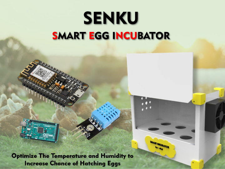
SENKU: Smart Egg Incubator
Smart Egg Incubator to Optimize The Temperature and Humidity using real-time wifi to Increase the Chance of Hatching Eggs.

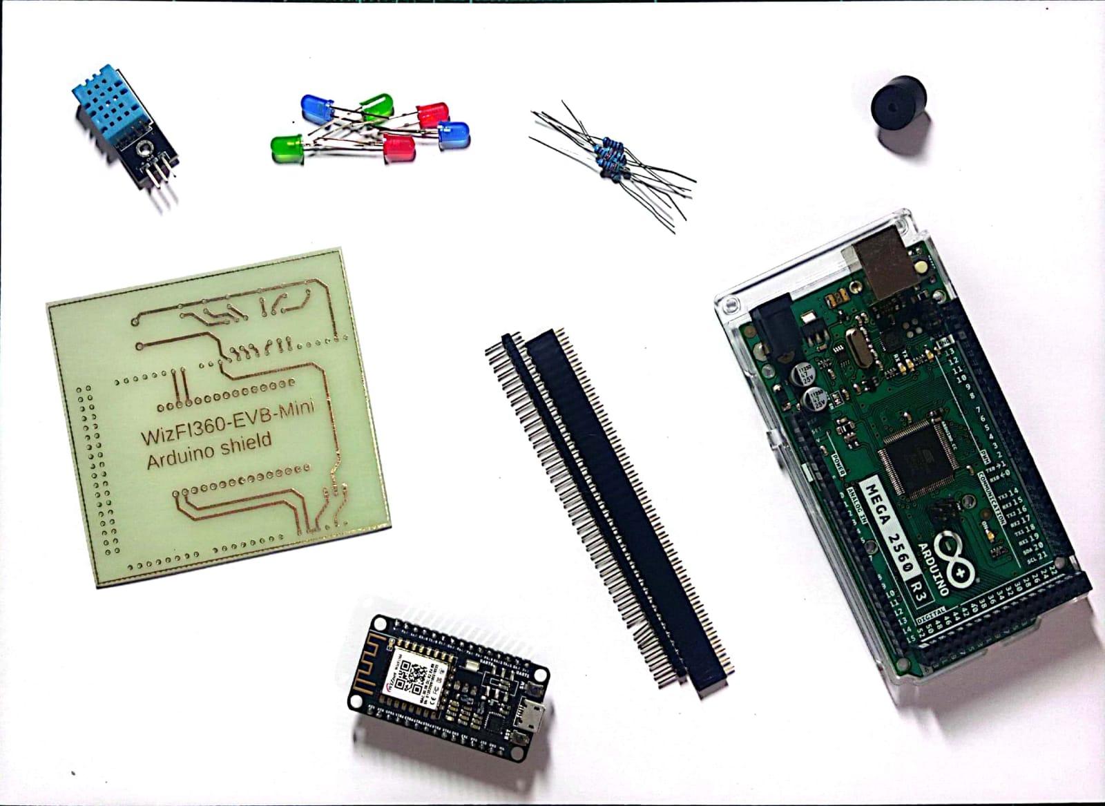
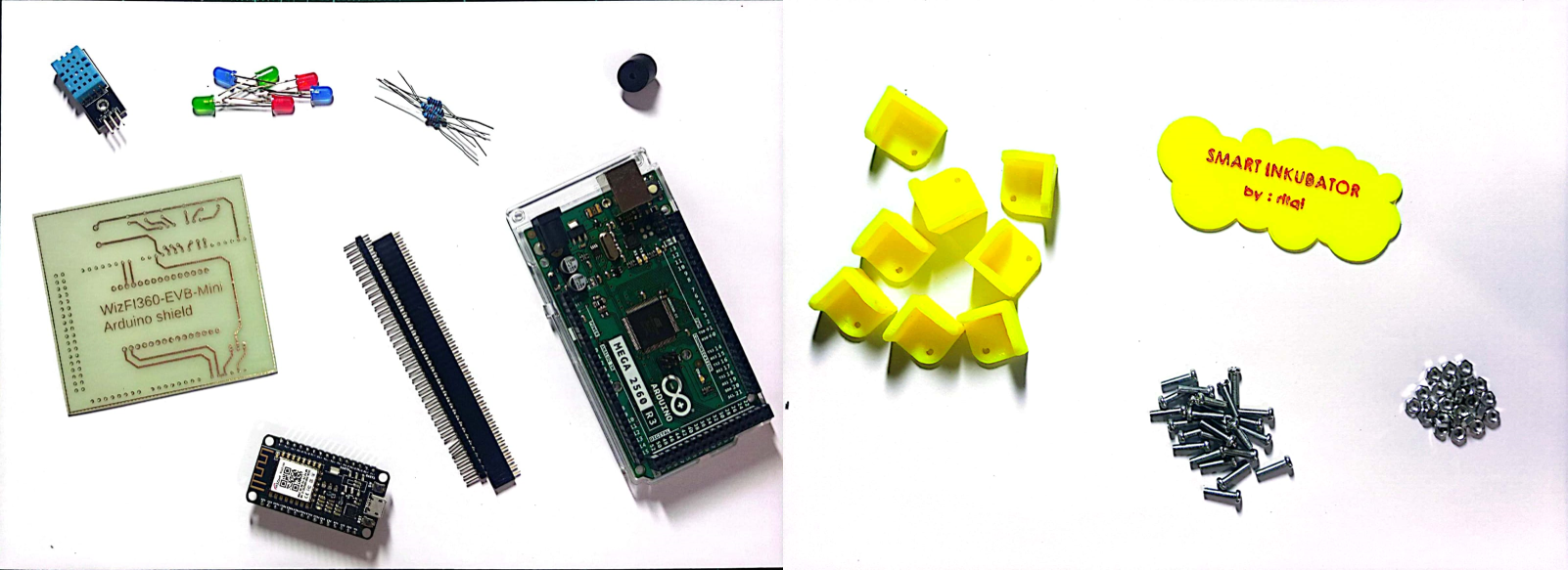
WIZnet - WizFi360-EVB-Mini
x 1

Arduino - Arduino Mega 2560
x 1

DFRobot - Gravity: DHT11 Temperature Humidity Sensor For Arduino
x 1

Arduino - Arduino IDE
x 1
MathWorks - Thingspeak
x 1

solidworks - SolidWork
x 1
weebly - Weebly - Weebly Website Builder
x 1
Story

The incubator machine is used to incubate chicken eggs into chicks. Stable conditions are needed to increase the chances of hatching chicks. Incubating chicken eggs using an incubator requires a total incubation period of between 21 – 22 days. The temperature of the hatching room during the incubation period of chicken eggs (18 days) is set at 37°-38°C, while during the hatching period (around 19-21 days) the temperature can be slightly increased to 39°C or kept at 38°C. The humidity is relative, during the incubation period, humidity is maintained at 50% - 55% and in the hatching period or on days 19-21 the humidity increases slightly, which is around 60%-65%.
Problem
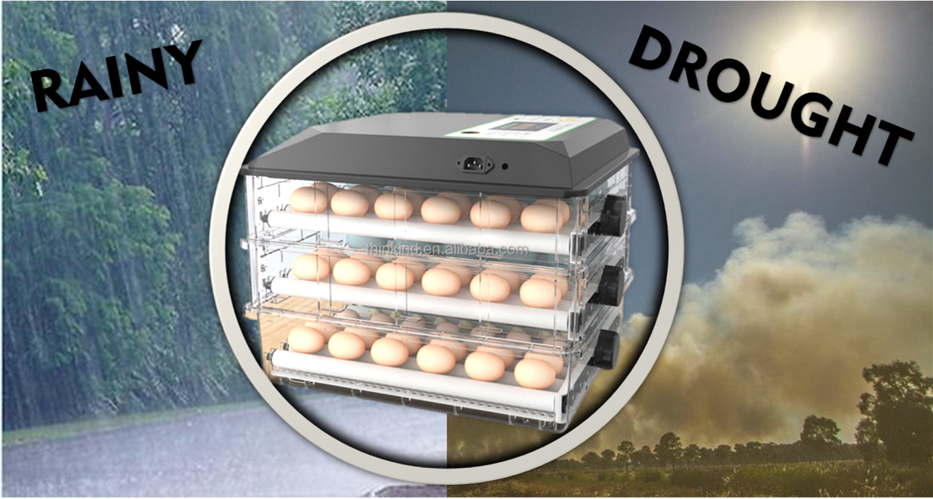
In some tropical countries, such as Indonesia, the weather can change at any time to be colder than usual, causing less than optimal heating which is usually set constant and also causing the hatching room to become more humid. This condition can reduce the chances of hatching chicks so further optimization needs to be done.
Solution
I will develop SENKU (Smart Egg Inkubator), a smart incubator machine which will monitor the temperature and humidity in the hatchery. This machine will adjust the temperature and humidity based on the data obtained from the sensor. This process will use machine learning to make decisions about increasing or decreasing temperature and temperature, so it is hoped that more optimal conditions will be created for eggs in the hatchery. I hope that this machine will increase the chances of hatching chicks to be higher.
How it works?
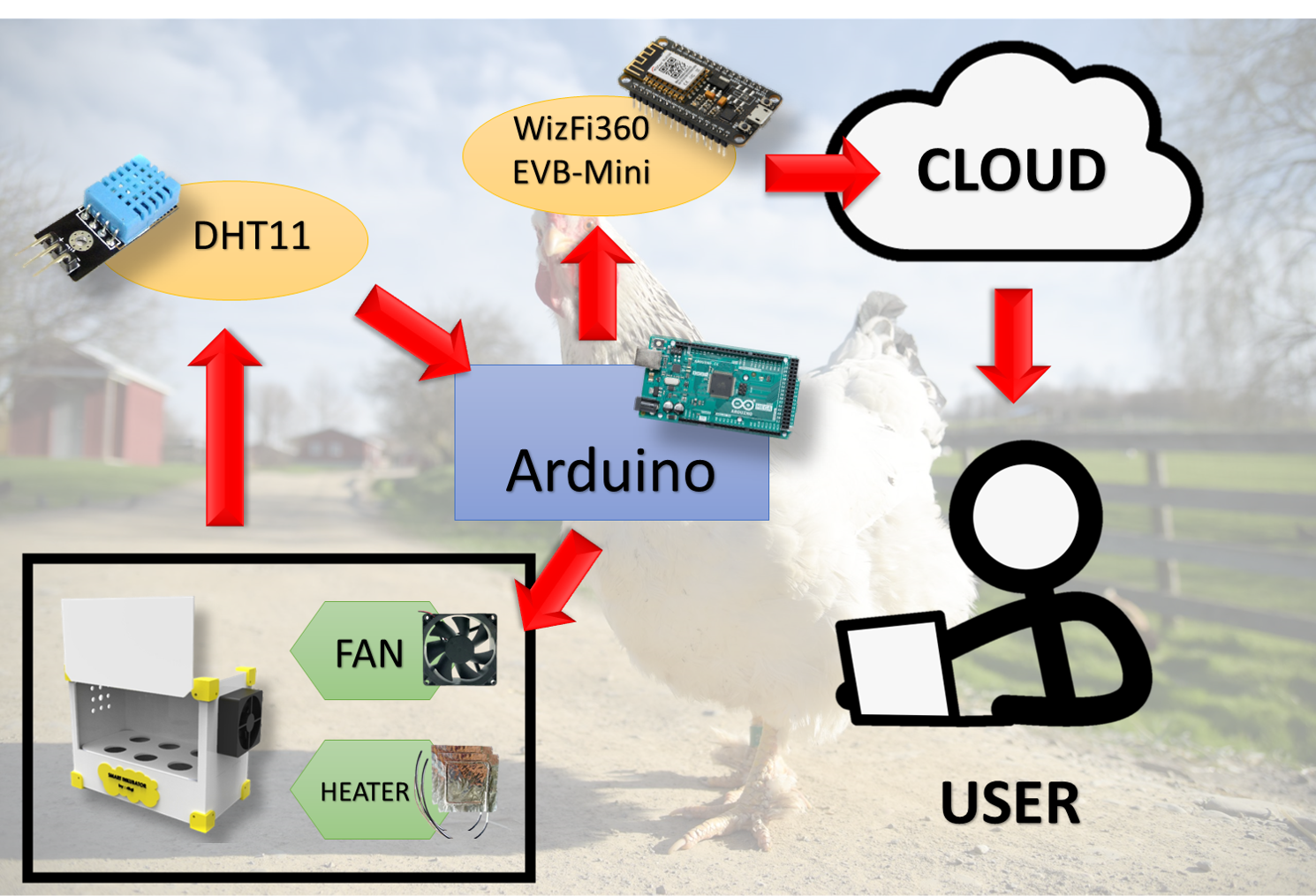
SENKU is built to see the temperature and humidity in the incubator and sends the data to the Arduino Mega 2560. Using the data obtained from DHT 11, Arduino will do the necessary to set and lower the temperature. The temperature setting is done by controlling the heating element and the humidity setting is done by the fan.
Arduinos that don't have cloud communication features will use the WizFi360-EVB-Mini. WizFi360-EVB-Mini will send data via wifi to the ThingSpeak data store. The data sent is in the form of temperature and humidity parameters which will be sent every 30 seconds. This data will be displayed on the monitoring website so that users can continue to update the condition of their incubator from anywhere and anytime directly.
As a note, the incubator used is in the form of a prototype to make the design process easier and less expensive, but if it is applied to an incubator it will actually work well. The incubator prototyping process will also be explained in this project.
Process and Steps
- Read DHT11 Sensor
- Test WizFi360-EVB-Mini connection
- Test wifi connection
- Send data to ThingSpeak
- Make Arduino-WizFi360 PCB shield using Eagle
- Test heater and blower using relay
- Design 3D prototype incubator using Solid Works
- Inkubator prototype assembly
- Develop a monitoring website using Weebly
- Test the device
Step 1: Read DHT11 Sensor
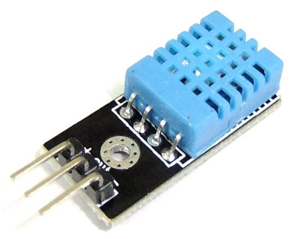
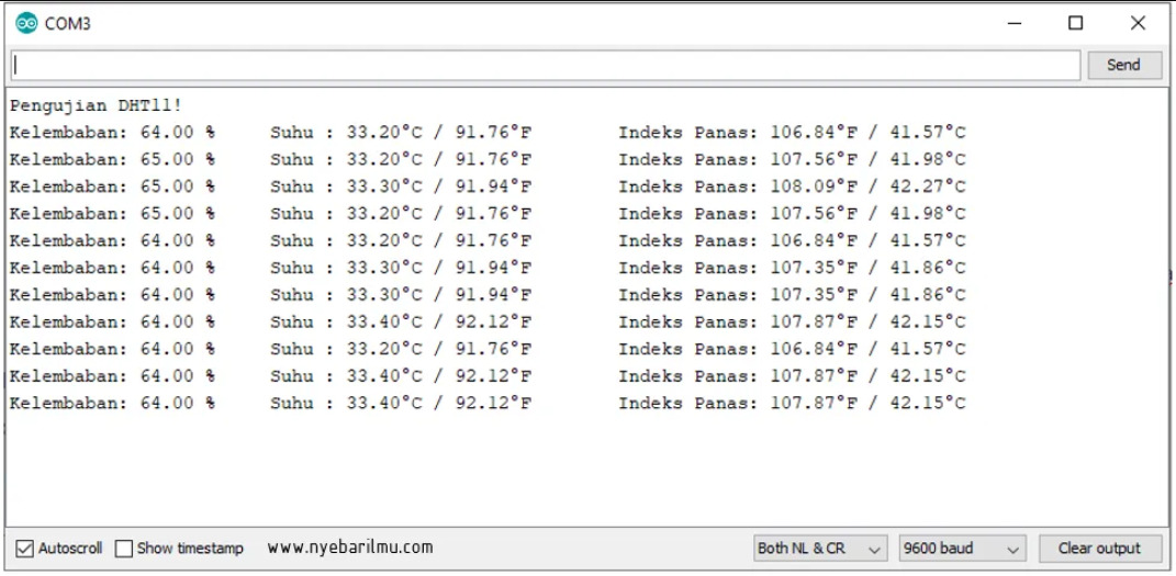
The DHT11 is a basic, ultra-low-cost digital temperature and humidity sensor. It uses a capacitive humidity sensor and a thermistor to measure the surrounding air and spits out a digital signal on the data pin (no analog input pins needed). It's fairly simple to use but requires careful timing to grab data.
The process of reading DHT11 can be done using Arduino, in this project a microcontroller is used. This sensor module is classified as a resistive element such as a temperature measuring device such as an NTC. The advantages of this sensor module compared to other sensor modules are in terms of the quality of reading sensing data, which is more responsive, which has speed in terms of sensing temperature and humidity objects, and the data that is read is not easily interfered with. DHT11 sensor readings can use the program on the GitHub link in the attachment or on the following link. The reading results are as follows.
Step 2: Test WizFi360-EVB-Mini connection
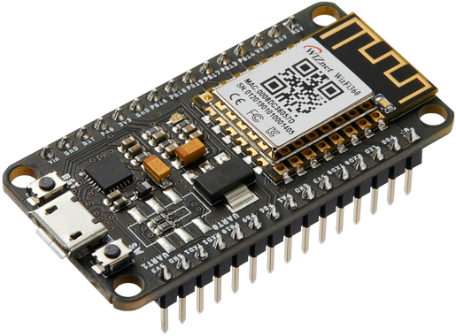
WizFi360-EVB-Mini is a compact development board for experiment, testing, and verification of WizFi360. WizFi360-EVB-Mini is the same form factor as the NodeMCU V2. WizFi360 is a low-cost and low-power consumption industrial-grade WiFi module. It is compatible with IEEE802.11 b/g/n standard and supports SoftAP, Station, and SoftAP+Station modes. The serial port baud rate can be up to 2Mbps, which can meet the requirement of various applications.
A brief AT command describes for operating of WizFi360 as TCP Client in single connection mode. If you need AT command example of another mode, see the documentation called "AT command examples". For more information you can check on this official documentation. In this project, a serial monitor on Arduino is used to test the WizFi360-EVB-Mini connection. Experimental results can be seen in the image below.
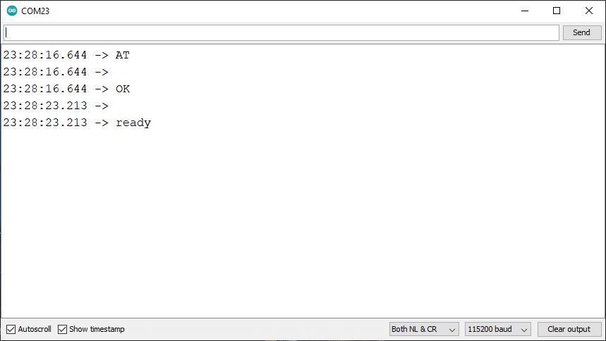
(1) WizFi360-EVB-Mini Setup
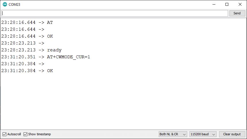
(2) Select Mode
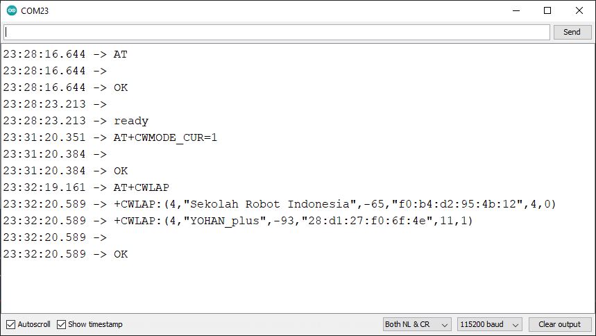
(3) Check available wifi
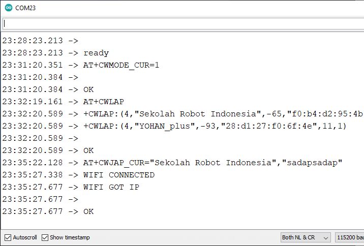
(4) Start connection to Wifi
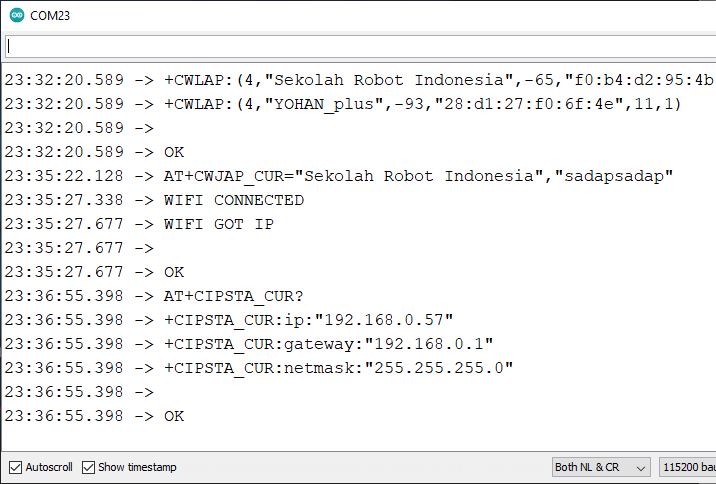
(5) Check Device IP
Step 3: Test wifi connection
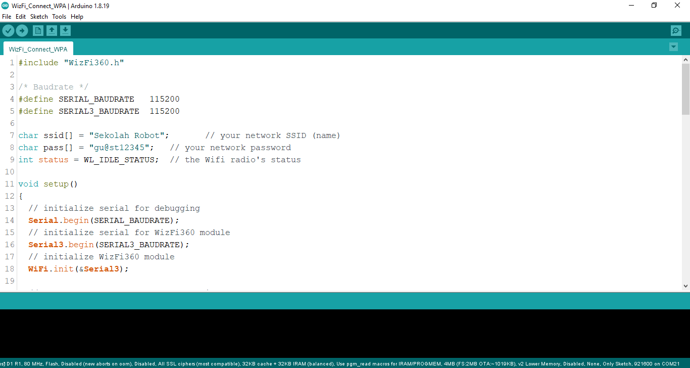
After the process of testing the WizFi360-EVB-Mini connection using AT-Command, then we can continue the next process. The next process is the trial of connecting Arduino Mega with wifi via WizFi360-EVB-Mini. The connection process between WizFi360-EVB-Mini and Arduino Mega is done using serial communication. The selected serial is serial communication 3. This process is quite easy to do because there is already a sample code that can be used in the library provided by Wiznet (or you can check to this github link). The thing that needs to be changed is the SSID and Password of the wifi that will be used.
Step 4: Send data to ThingSpeak
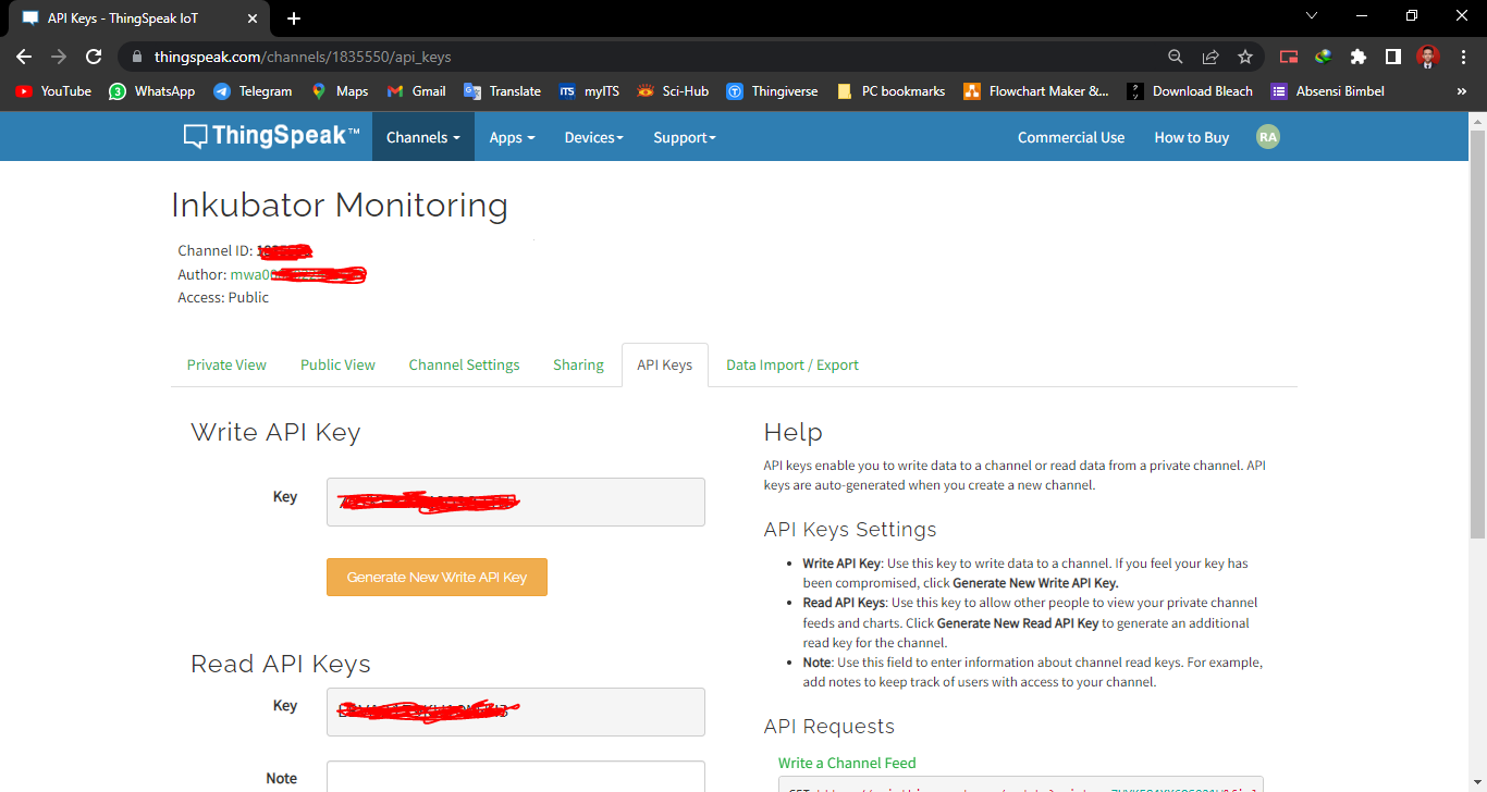
The data that has been acquired from the DHT11 sensor has two labels, temperature and humidity. This data needs to be sent to the data storage area. In this project, ThingSpeak was chosen to carry out this task. ThingSpeak is open-source software written in Ruby which allows users to communicate with internet-enabled devices. It facilitates data access, retrieval and logging of data by providing an API to both the devices and social network websites. ThingSpeak was originally launched by ioBridge in 2010 as a service in support of IoT applications. To access ThingSpeak, you need an API Key which can be obtained directly on the ThingSpeak website. You can copy the Write API Key as shown below.
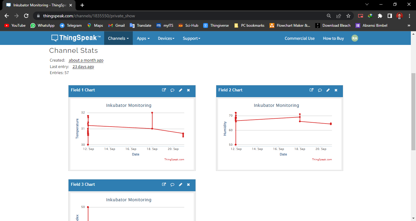
Next, enter the code sample that has been provided by Wiznet in the existing library (or you can check to this github link). Insert the required information (SSID, password, write API key, etc.). Do not forget to change the data transmission section to match the output format of the sensor used for data acquisition. If the data transmission is successful, the graphic display will change and display the data that has been sent as shown below.
Step 5: Make Arduino-WizFi360 PCB shield using Eagle
At this stage the Arduino-WizFi360 shield is made to simplify the installation process on the Arduino. Arduino shield is a term for additional modules with various functions, most of which are compatible with Arduino pins, so how to connect them to Arduino can be by arranging them on the Arduino board. On the Arduino-WizFi360 Shield that will be made, the connection between the two modules will be on the PCB so that it does not require cables and is easier to install.
In this project, the Eagle application is used to carry out the design process of the Arduino-WizFi360 Shield PCB. EAGLE is a scriptable electronic design automation (EDA) application with schematic capture, printed circuit board (PCB) layout, auto-router and computer-aided manufacturing (CAM) features. EAGLE stands for Easily Applicable Graphical Layout Editor (German: Einfach Anzuwendender Grafischer Layout-Editor) and is developed by CadSoft Computer GmbH. The company was acquired by Autodesk Inc. in 2016.
The process begins with the schematic design process of the board to be made. The components that will be used are the schematic of the Arduino Mega and the Wizfi360-EVB-Mini. It has been explained in the documentation that the size of the Wizfi360-EVB-Mini is the same as the MCU node, so we can use the schematic of the MCU node to replace it. All Schematic and board files can be download on this link.
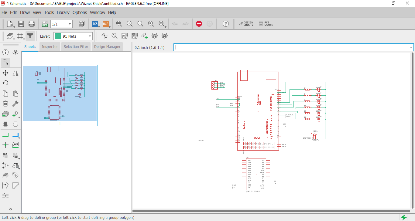
Added several components of leds and buzzers which will be used as indicators of temperature and humidity parameters. Each parameter has 3 LEDs as indicators. The three LEDs will be used to see whether the parameters are in accordance with the requirements of the incubator or not. The buzzer is used to notify the user if the condition of the incubator is too far from the specified requirements.
After the schematic creation process is complete, the next process is the process of making the board file. In this section, the components are arranged to fit and as neatly as possible to form a shield. In this process a path is made from one component to another. The results of the board can be seen in the image below.
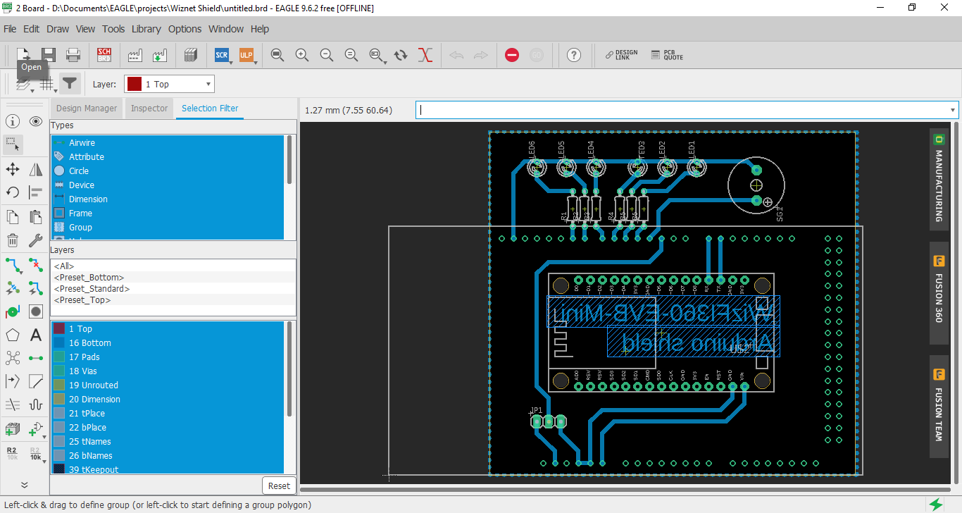
The final result of the PCB can be seen in the image below.
Step 6: Test heater and blower using relay
This process will test the readiness of the heater and fan to be controlled using an electronic switch. The components to be used are 2 channel relays. A relay is an electrically operated or electromechanical switch composed of an electromagnet, an armature, a spring and a set of electrical contacts. The electromagnetic switch is operated by a small electric current that turns a larger current on or off by either releasing or retracting the armature contact, thereby cutting or completing the circuit. Relays are necessary when there must be electrical isolation between controlled and control circuits, or when multiple circuits need to be controlled by a single signal.
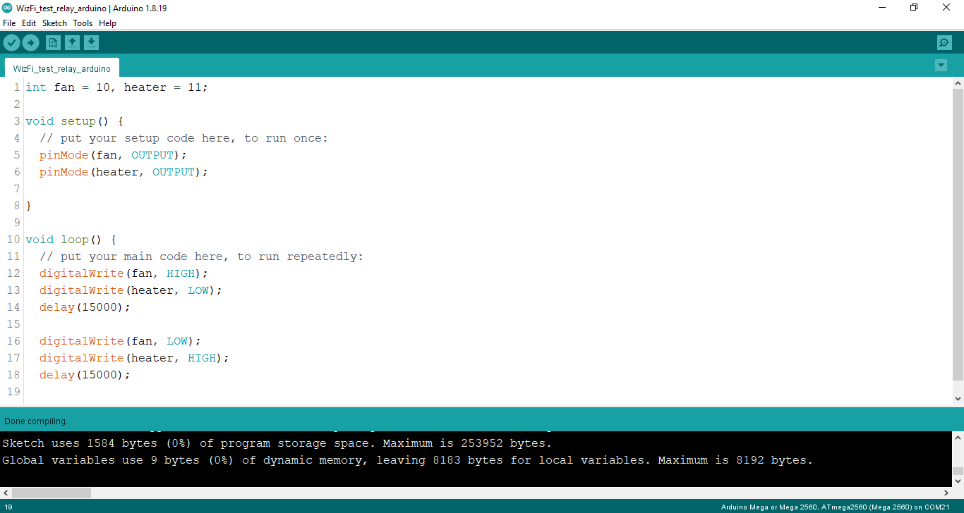
For this process, we will try to make the heater and fan turn on automatically by using digital pins on the Arduino Mega. The process is quite simple because we only need to use the digitalWrite command when programming. You can try it using the code in the attachment or using this github link.
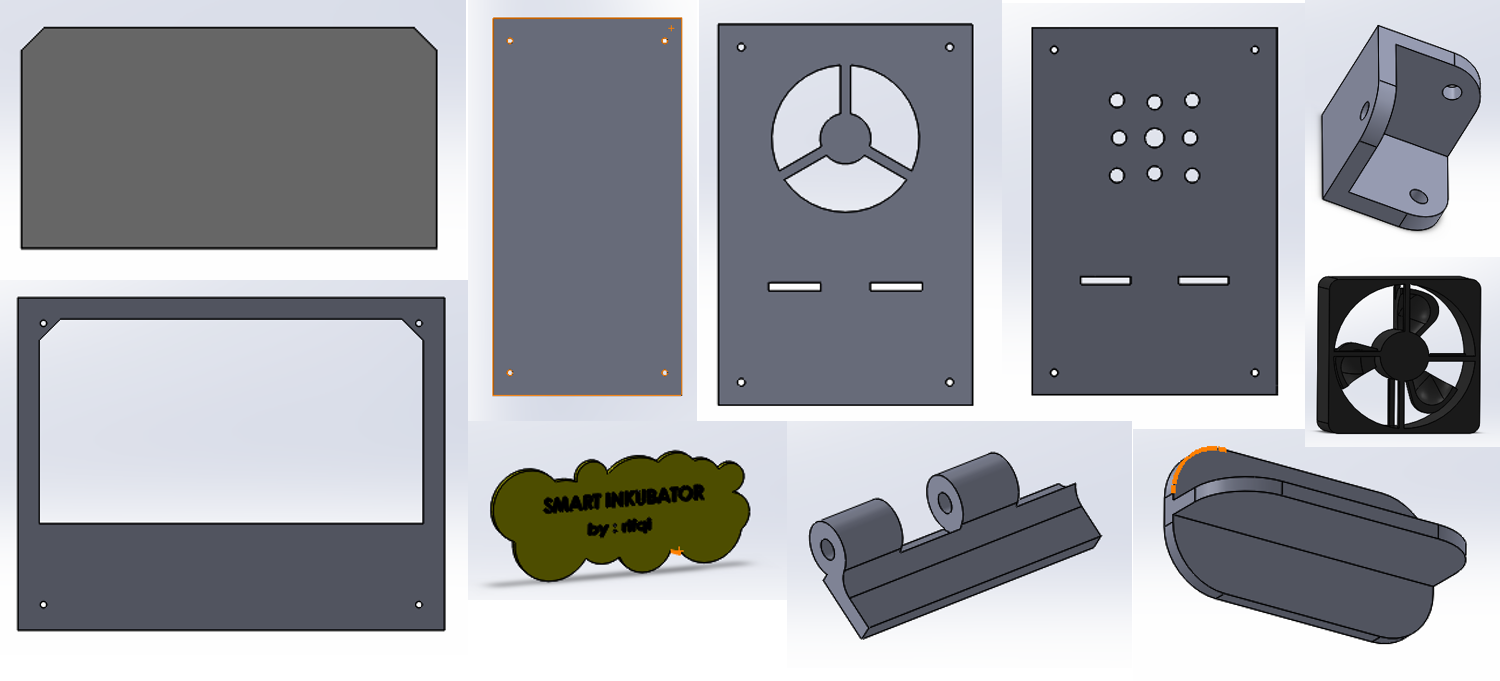
Step 7: Design 3D prototype incubator using Solid Works
At this stage, the process of making a prototype incubator will be explained using a solid works application. SolidWorks is a solid modeling computer-aided design (CAD) and computer-aided engineering (CAE) application published by Dassault Systèmes. According to the publisher, over two million engineers and designers at more than 165,000 companies were using SolidWorks as of 2013. According to the company, fiscal year 2011–12 revenue for SolidWorks totaled $483 million.
The first process in making this incubator prototype is making parts of the incubator. The incubator is designed in the form of a box with a size of 10 cm x 15 cm x 20 cm. The manufacturing process is designed using acrylic with a thickness of 3 mm. Acrylic was chosen because it is easy to manufacture because it can be cut according to what we want using a laser machine. After the process of making walls is made, the next process is the process of making supports. Supports will be installed at each corner of the incubator. This support will use a nut and a hexnut for installation. The supports will be designed to glue each side of the incubator wall together. The next part is the door design process that will be used by the user to put eggs into the incubator. This section is made by cutting one of the front walls of the incubator and connecting it using hinges. The last part is the process of making holes for fans and air circulation channels. You can see the parts that have been made in the image below. All 3D file can be downloaded on this link.
The next process is to create an assembly file which is a combination of all the parts that have been made. Assembly files are used to visualize the whole tool when it is combined into one part. This process also ensures that the size and plotting of each section is right when combined into one. The merging process uses the mates feature to attach one part to another. You can check the pictures and videos below for details of the assembly file.
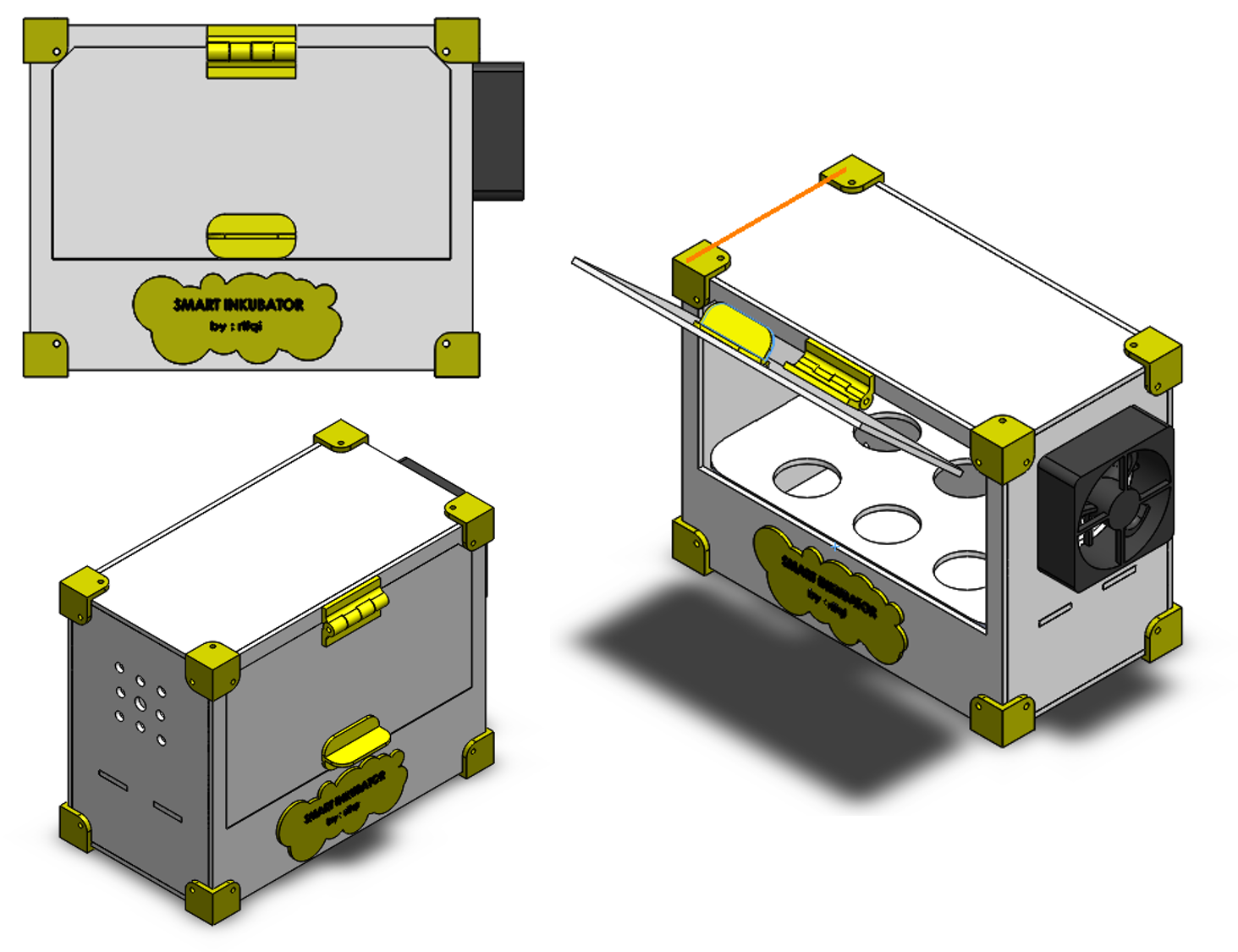
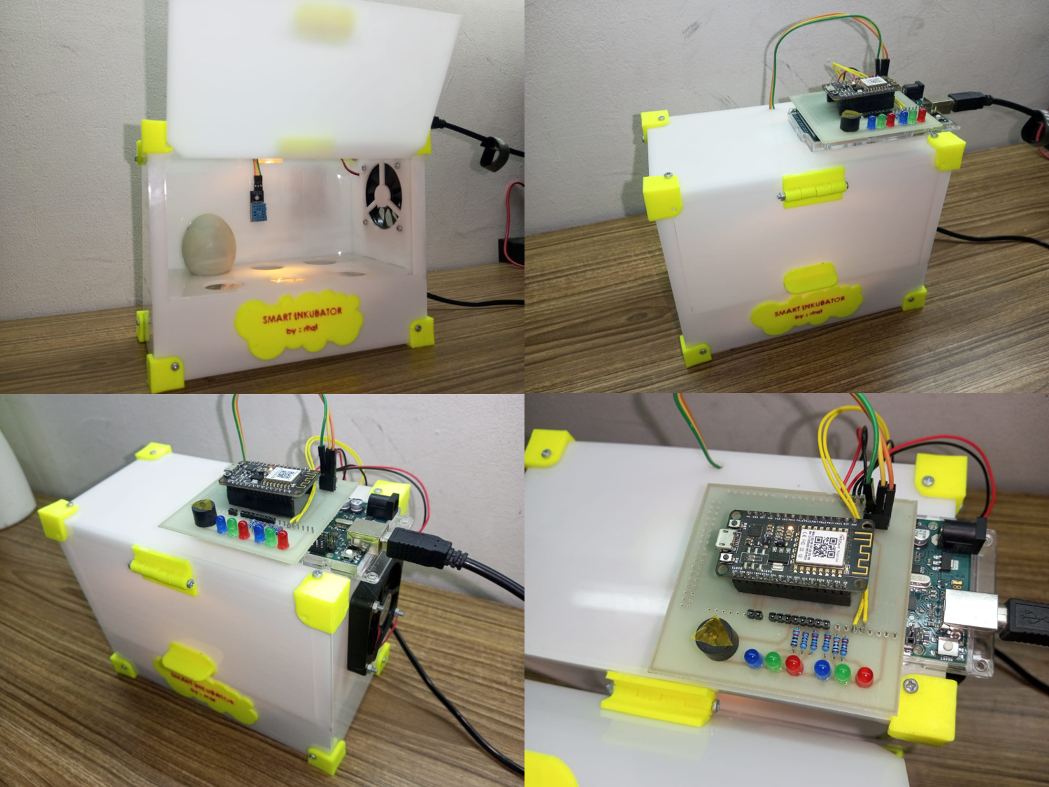
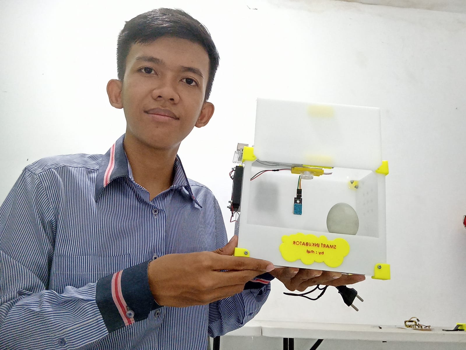
Step 8: Inkubator prototype assembly
The designs that have been made will then be printed. The printing process uses materials that are in each component. The walls of the incubator will be printed using acrylic, while the connectors will be printed using filaments on a 3D printer. After printing, we can immediately carry out the merging process following the design in the assembly file. For the results after the merging process of all parts can be checked in the image below.
Step 9: Develop a monitoring website using Weebly
The device is ready to use and is functioning properly. The data has also been stored on the ThingSpeak database. At this stage a monitoring website will be created using the Weebly platform. Weebly is a tool for creating free websites. Using a widget format, it allows users to create pages with just a few clicks, drag and drop different page elements (images, text, or interactive content, etc.) onto the page and populate the content. This site was created by David Rusenko, Dan Veltri, and Chris Fanini, and all who attended Penn State for their undergraduate degrees. Weebly was listed in Time magazine as the Fourth Best of the fifty sites in 2007.
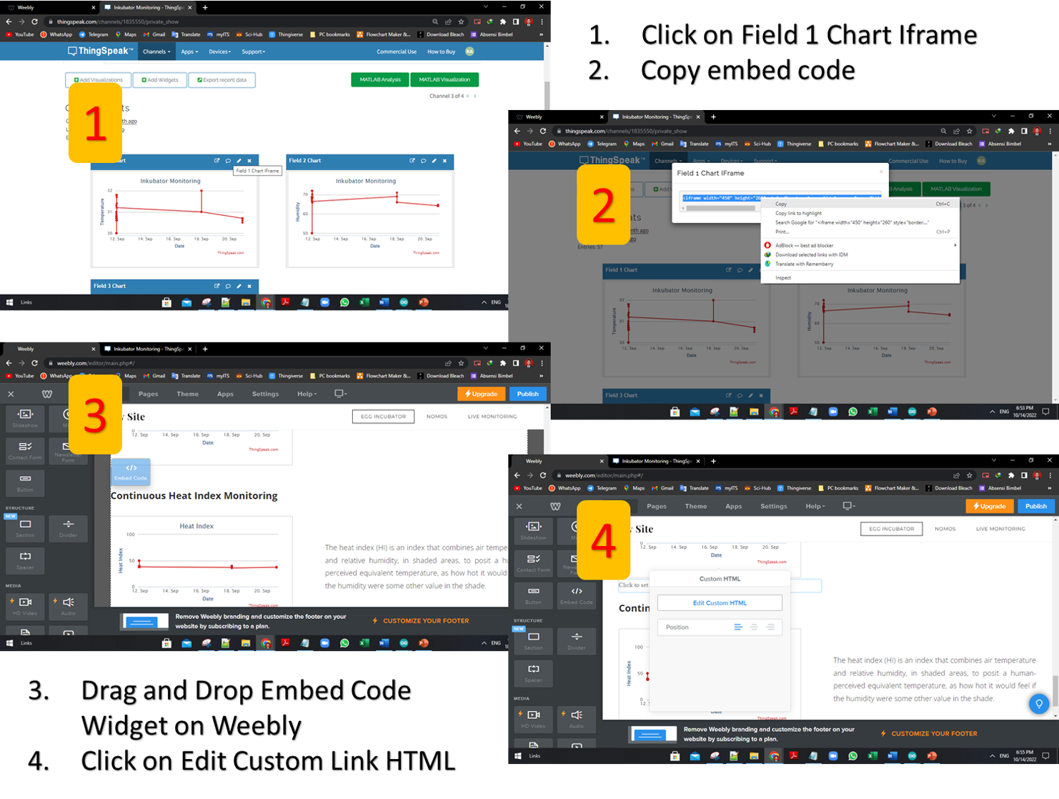
Weebly is very easy to use. Users simply drag and drop on the components that have been provided on the left. The page can contain some useful information for the reader. In addition, it can also connect the ThingSpeak database with Weebly in the form of a graphical display or in the form of a simple widget so that it will be easier for users to monitor the condition of the incubator.
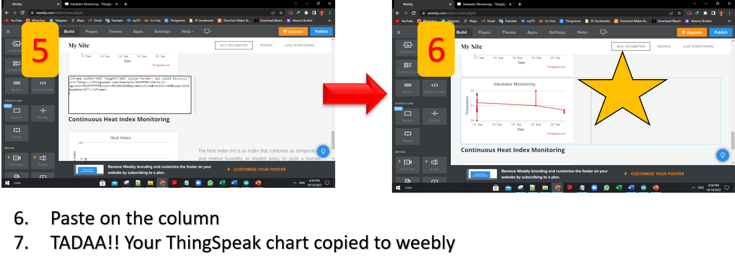
You can copy graphics or widgets from the ThingSpeak website into your weebly website by following the easy steps below. You can check my monitoring website on : https://rifqi-abdillah.weebly.com/egg-incubator.html
Step 10: Test The Device
The results and test trials from SENKU can be seen in the video below.
Closing
SENKU can be used to monitor temperature and humidity in egg incubators. SENKU will also carry out the process of adjusting temperature and humidity to match the optimal requirements needed by eggs in the incubator machine. This optimization is done by adjusting the heater and fan so that it is expected to make the chances of eggs hatching more optimally.
The developer hopes that SENKU can be one of the solutions in using the incubator machine so that the process of monitoring the temperature and humidity can be more optimal. The developer also hopes that in the future, SENKU will be better developed, because there are still many features that can be explored more deeply, for example by using image processing and bio-electronics.
In the future, the developer hopes that SENKU will not only be a prototype but can also be applied in real terms to help chicken farmers. Support from various parties is needed for this, especially other developers, farmers, and the government, to develop SENKU together to become a better version.
For Makers, By Makers!
SEE YOU ON THE NEXT PROJECT! :)
-
SENKU code
All code that used in SENKU Project

-
SENKU schematics
All schematic and board that used in SENKU Project
-
SENKU 3D file
All 3D file that used in SENKU Project