
AMG Sprinkbot: Automated Mint Garden Smart Sprinkler System
AMG Sprinkbot is a project for a smart mint garden, automating watering with soil moisture sensing for optimal growth and care.
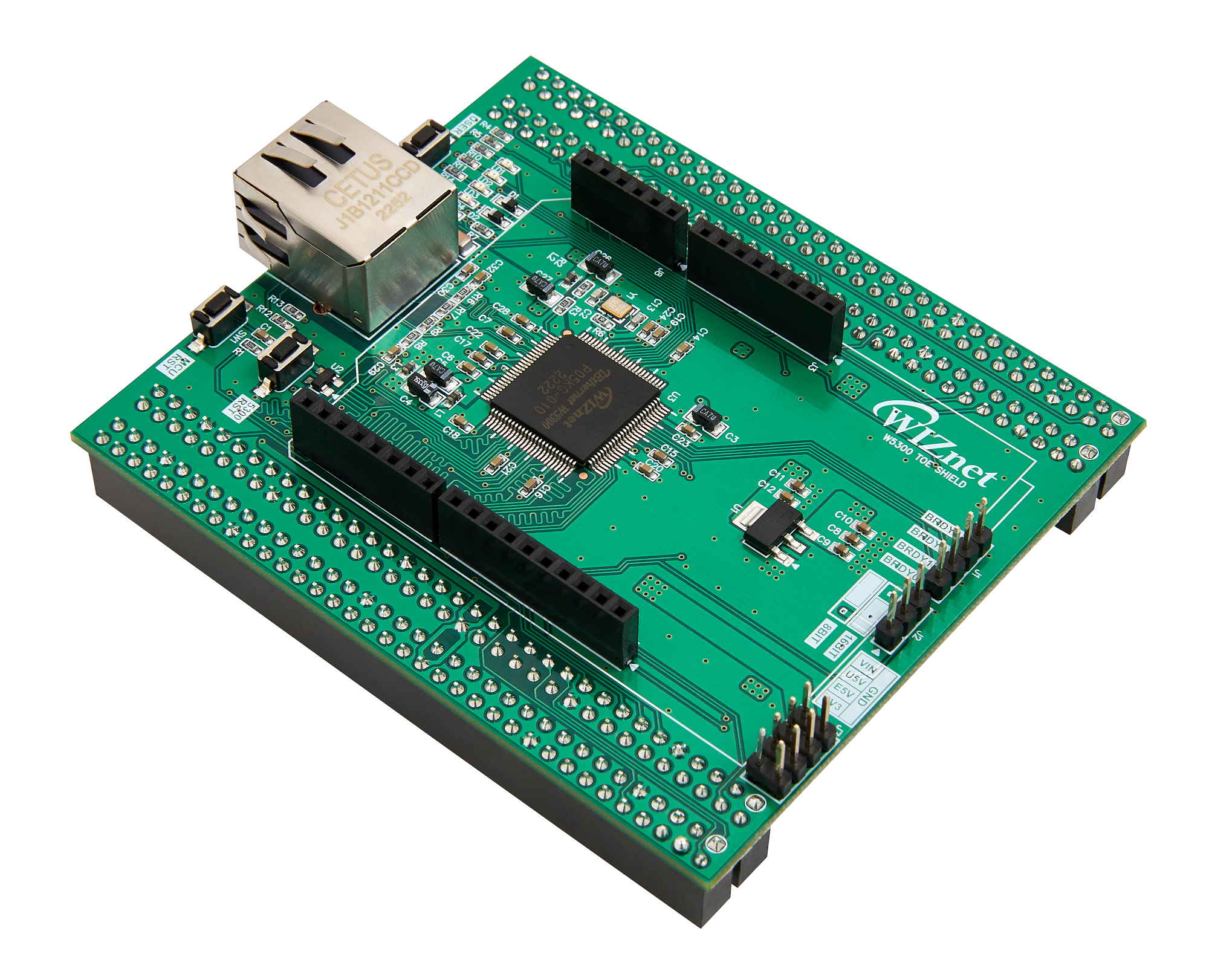
WIZnet - W5300-TOE-Shield
x 1
AMG Sprinkbot: Automated Mint Garden Smart Sprinkler System
Story

A few months ago, I started enjoying drinking tea. I also became interested in trying mint-infused tea. I quickly bought a mint plant and planted it in a pot. It brought me joy as I could make mint tea frequently. However, two months ago, I had to leave the city for almost a week, and there was no one to water my mint plant. Moreover, my country's tropical climate caused the soil in the pot to dry out quickly, resulting in the death of my mint plant, and I could no longer make mint tea.
Imagine being an avid mint gardener, facing the constant challenge of ensuring your precious plants receive the right amount of water at the right time. Overwatering leads to rot, while underwatering results in the most. This frustrating cycle calls for a more innovative solution.
Problem

An automatic sprinkler is vital in using mint plants to ensure they receive sufficient water when users cannot manually water them. Mint plants, which require the proper soil moisture to thrive, can encounter problems if they lack water for an extended period. The challenge lies in maintaining an optimal watering schedule for mint plants, which varies based on weather, humidity, and soil moisture levels. A traditional irrigation system cannot adapt to these changing conditions, leading to inefficient water usage and potential plant damage.
Solution

The "Automated Mint Garden" project offers a revolutionary solution. By combining smart sprinkler technology with soil moisture sensing, this system automatically detects and waters the plant's water needs accordingly. The setup can be programmed to adjust watering schedules based on real-time data, ensuring the mint plants receive just the right amount of water for healthy and vibrant growth.
How It Works?
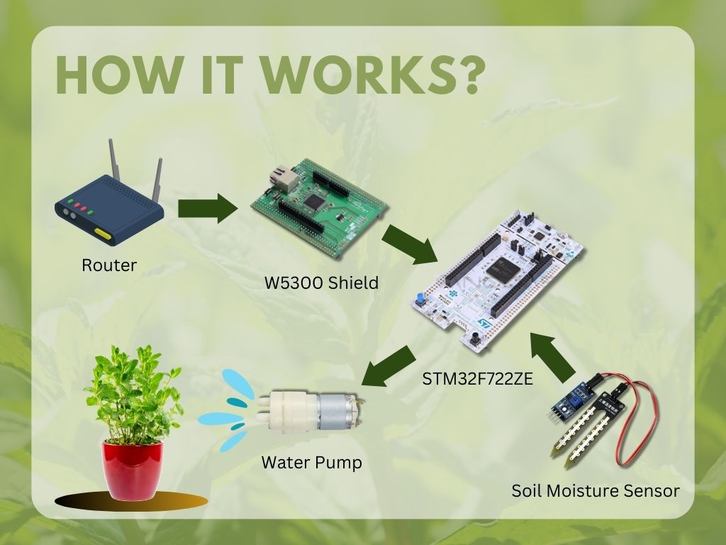
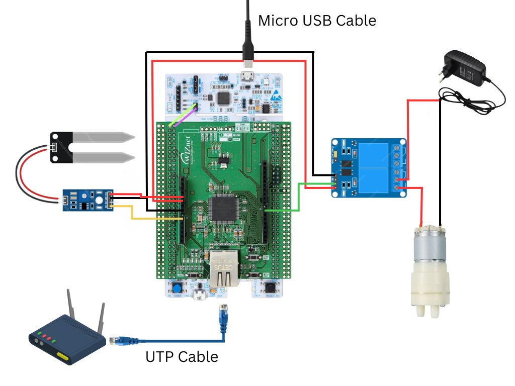
The main processor in the system is STM32F722ZE, which is responsible for controlling and managing all operations. The W5300 Arduino shield connects STM32F722ZE to the internet router using UTP cables. STM32F722ZE will obtain time data from the internet to effectively schedule the plant watering cycles. Additionally, it receives soil moisture data from the soil moisture sensor, enabling the system to provide adaptive irrigation based on soil moisture levels. This intelligent system adjusts the irrigation volume and frequency according to the plant's needs, ensuring healthy plant growth and efficient use of water resources.
Hardware
- STM32F722ZE
- W5300 arduino shield
- UTP cable
- Soil moisture sensor
- Relay
- Mini water pump 12V DC
- Power supply
Software
- STM32CubeIDE
- Tera Term
- Eagle
Process and Steps
- Test simple network time protocol and adjustment
- Read time and scheduling
- Read soil moisture sensor
- Water pump control test
- Make Arduino shield
- Watering system assembly
- Device Test
Step 1: Test SNTP Program and Adjustment

SNTP (Simple Network Time Protocol) is a lightweight and simplified version of NTP (Network Time Protocol) designed to synchronize the clocks of computer systems over a network. Its primary purpose is to obtain accurate time information from time servers on the internet or local network and adjust the local system time accordingly. SNTP operates in a client-server model, where the client sends a request to the server, and the server responds with the current time. It does not involve complex timekeeping algorithms like NTP, making it more suitable for devices with limited computational resources or applications where high-precision time synchronization is not critical. SNTP is commonly used in various networked devices, IoT applications, and systems that require reasonably accurate timekeeping without the overhead of full NTP functionality.
Wiznet has provided several simple examples of using your board and W5300 Arduino Shield directly. You can access the programs on the official Wiznet website. Several programming languages are available, including Arduino-based, C language, and MicroPython. However, there are some considerations regarding the compatibility of your board and the available example programs. Please refer to Getting Started for configuring the development environment or examples of usage. The board I'm using for this project only supports the C programming language. If you are using the same board, you can download the code from this link.
After downloading the program from the website, open STM32CubeIDE, open your project, and first, modify some code in your program. In the main.c file, you need to change the IP settings on your board.
wiz_NetInfo net_info =
{
	.mac = {0x00, 0x08, 0xDC, 0x12, 0x34, 0x56}, // MAC address
    .ip = {192, 168, 0, 10},                     // IP address
    .sn = {255, 255, 255, 0},                    // Subnet Mask
    .gw = {192, 168, 0, 1},                     // Gateway
    .dns = {8, 8, 8, 8},                         // DNS server
    #ifdef APP_DHCP
          .dhcp = NETINFO_DHCP                         // Dynamic IP
	#else
          .dhcp = NETINFO_STATIC                       // Static IP
	#endif
};
In w5x00_demo.h, you need to uncomment the application that you want to try. In this section, I am trying the SNTP program.
//#define APP_DHCP
//#define APP_DNS
//#define APP_HTTP_SERVER
//#define APP_MQTT_PUBLISH
//#define APP_MQTT_SUBSCRIBE
//#define APP_MQTT_PUBLISH_SUBSCRIBE
#define APP_SNTP
//#define APP_TCP_CLIENT_OVER_SSL
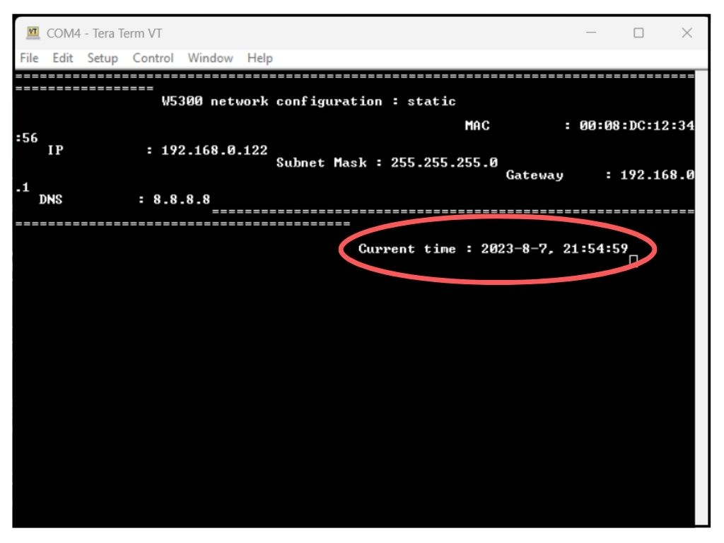
//#define APP_LOOPBACKLastly, in w5x00_sntp.c, you need to change the timezone variable according to your country. In the case of Indonesia, which uses GMT+7, I changed the variable to 37. Upload the program to your board, then open the Tera Term application to use it as a serial monitor. Here are the results of the SNTP program readings.
Step 2: Read Time and Scheduling

Scheduling watering for mint plants is crucial to maintaining their health and optimal growth. Mint plants require consistent moisture in the soil, but overwatering can harm their development. We have successfully accessed the time using the SNTP program in the previous section. In this part, we will create a function to extract the hour and minute from the time data, enabling us to create a watering schedule for mint plants.
What needs to be done is to create a function in main.c to display the hour and minute. We can achieve this by modifying the sntp_demo() function and adding return functions. We must create two functions, one for the hour and another for the minute. You can refer to the code below.
void get_time_hour(wiz_NetInfo *net_info){

	  int hour;
	  int hour;
	  uint32_t start_msec = 0;
	  datetime time;

	  ...

	  hour = time.hh;
	  return hour;
}

void get_time_minutes(wiz_NetInfo *net_info){

	  int minutes;
	  int hour;
	  uint32_t start_msec = 0;
	  datetime time;

	  ...

	  minutes = minutes.hh;
	  return minutes;
}
To schedule watering for mint plants, you can utilize the time data accessed through the SNTP program. Based on the obtained time information, you can set the watering schedule according to your preferences and the needs of your mint plants. Typically, morning and late afternoon are considered favourable times for watering. For this project, the watering schedule will be set at 7 AM and 5 PM, but you can adjust it to suit your specific requirements.
Morning is ideal for watering because the temperature is relatively low, and the wind is usually calmer. This helps reduce water loss due to evaporation, making water absorption more efficient for the plants. Additionally, watering in the morning allows the plants to absorb nutrients and water throughout the day. Late afternoon is also a good time to water mint plants. During this time, the temperature decreases, and the sunlight is less intense, minimizing water evaporation. Watering in the late afternoon allows the plants to prepare for the night when photosynthesis activity decreases.
You can create a schedule by adding the following code to main.c.
 /* USER CODE BEGIN WHILE */
  while (1)
  {
	  int hours, minutes;
	  hours = get_time_hour(&net_info);
	  minutes = get_time_minutes(&net_info);
	  int target1 = 7;
	  int target2 = 17;
	  int water_flag = 0;

	  if (hours == target1 && minutes == 0 && water_flag == 0){
		  // watering command:
		  water_flag = 1;
	  }
	  if ((target1 + 1) == hours){
		  water_flag = 0;
	  }

	  if (hours == target2 && minutes == 0 && water_flag == 0){
		  // watering command:
		  water_flag = 1;
	  }
	  if ((target2 + 1) == hours){
		  water_flag = 0;
	  }

	   /* USER CODE END WHILE */

       /* USER CODE BEGIN 3 */
   }
Step 3: Read Soil Moisture Sensor
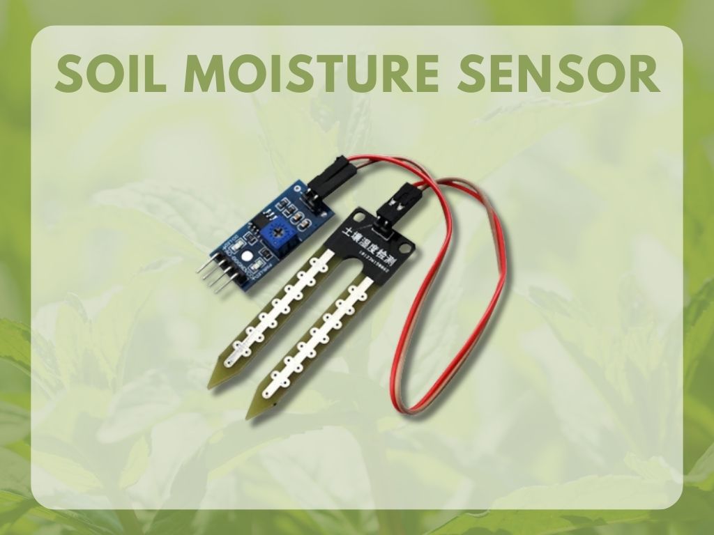
A soil moisture sensor is a device used to measure the amount of water present in the soil. It helps monitor and assess soil moisture levels, which is critical for plant growth and irrigation management. The sensor typically consists of two or more probes inserted into the soil. When the soil is wet, it conducts electricity better, leading to a lower resistance between the probes. In contrast, when the soil is dry, the resistance between the probes increases. By measuring this resistance, the sensor can determine the soil's moisture content and provide data that can be used to automate irrigation systems or make informed decisions regarding plant watering schedules.
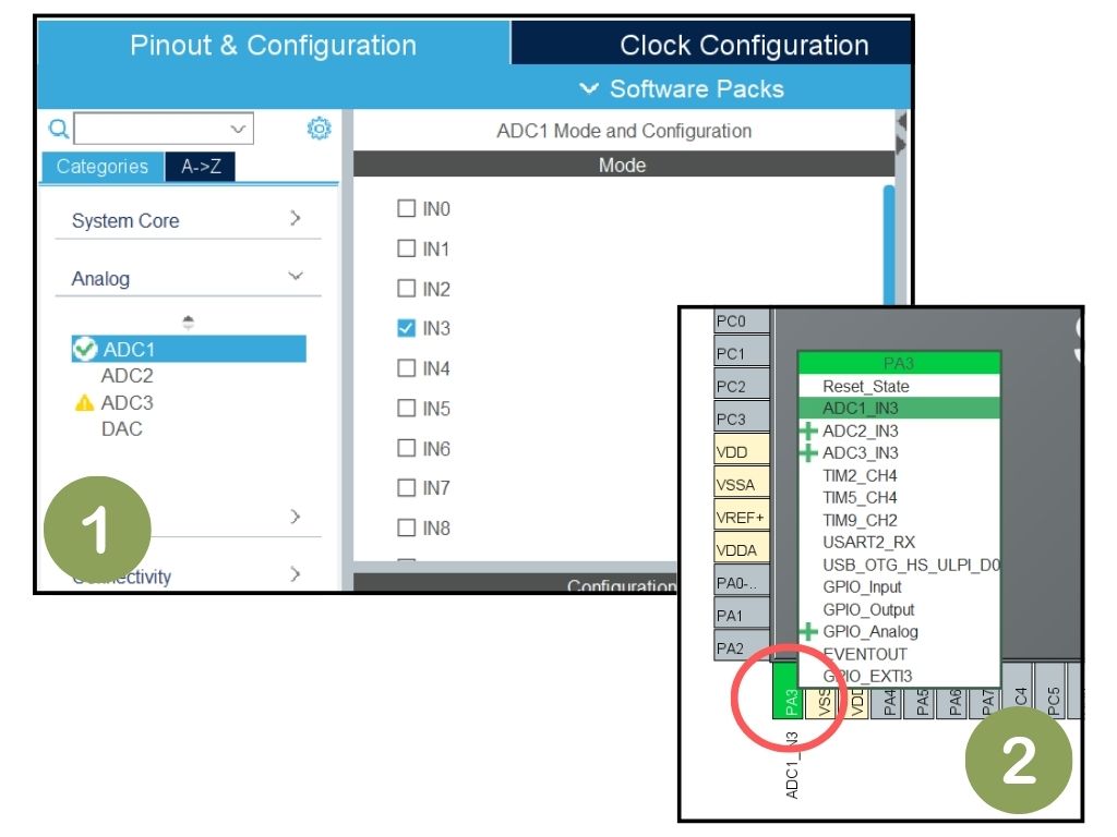
The first thing you need to do is to edit the ioc file within the project. You need to add pin declarations based on the datasheet on the official Wiznet website. Firstly, activate ADC1 in the Analog section and select the pin to be used on the board. In this case, I will use pin IN3, connected to pin PA3 on the Nucleo-144 board. The chosen pin is also connected to the W5300 Arduino shield's A0 pin, making it easier to access and add the shield board later.
Next, you can add the following code to your main.c file. If you observe, the code used is similar to what is used on Arduino, making it easy to understand. This code will provide output as ADC values read by STM32F722ZE through pin PA3.
 /* USER CODE BEGIN WHILE */
  while (1)
  {
      HAL_ADC_Start(&hadc1);
  	  // Wait for ADC conversion to complete
      HAL_ADC_PollForConversion(&hadc1, HAL_MAX_DELAY);

      // Read the ADC value
      uint16_t adcValue = HAL_ADC_GetValue(&hadc1);

      // Do something with the ADC value
       printf(" Current ADC : %d", adcValue);

      // Stop ADC conversion
      HAL_ADC_Stop(&hadc1);

      // Add a delay before next conversion (if needed)
      HAL_Delay(100);
    /* USER CODE END WHILE */

    /* USER CODE BEGIN 3 */
  }
Next, I will test the sensor to observe the values it produces for three soil categories. The first category is arid soil, the second is moist soil, and the third is wet soil due to watering. I will use these values to determine the system's thresholds for the irrigation process.
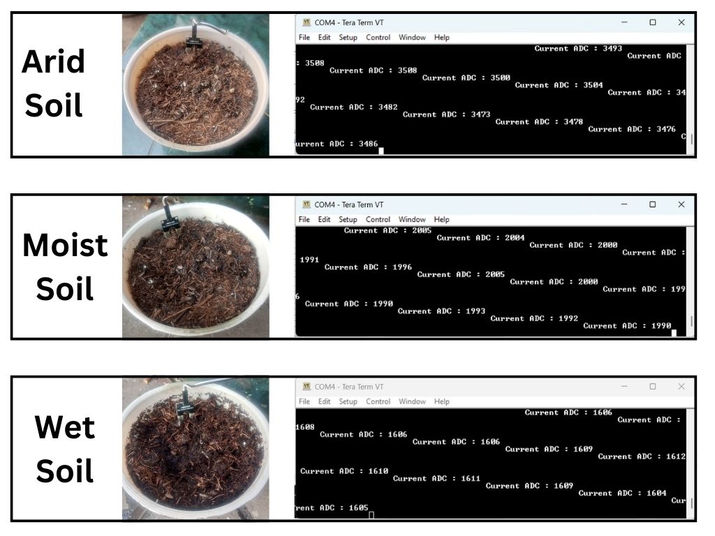
The system will provide more irrigation for the dry soil category to restore the soil's moisture level, ensuring that mint plants can obtain optimal nutrients. The system will provide regular watering in the moist soil category to maintain the soil's moisture level appropriately. However, no irrigation will be provided for the wet soil category to prevent the mint plants from experiencing overwatering conditions. Through these settings, the system can deliver adaptive irrigation based on the soil conditions for the mint plants.
Step 4: Water Pump Control Test
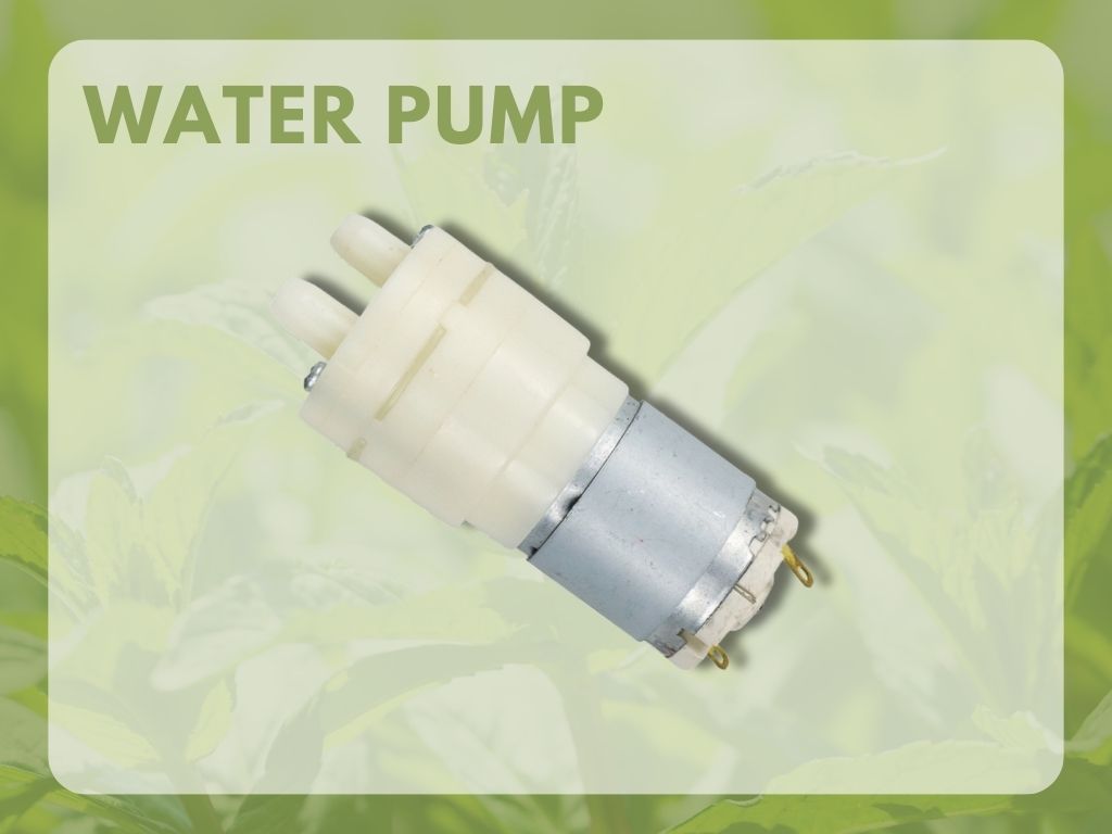
A water pump 12V DC is a device that is designed to pump water using a 12-volt direct current (DC) power source. It is commonly used in various applications, such as aquariums, fountains, irrigation systems, and other water circulation systems. When the 12V DC power is supplied to the water pump, it activates an impeller or rotor that creates a water flow, propelling it from one location to another. The speed and flow rate of the water pump can often be controlled by adjusting the voltage supplied to it. This allows for easy water flow and pressure regulation, making it a versatile and widely used component in many water-related applications.
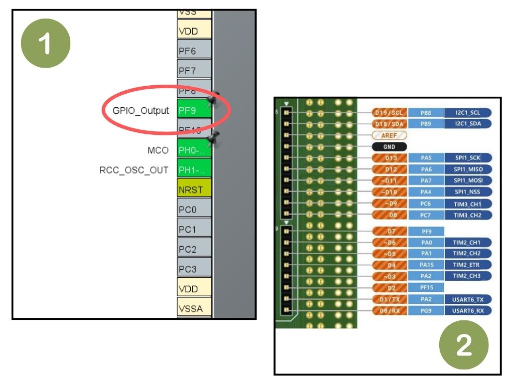
You need to declare the pins you will use as outputs in the ioc file within your project. In this project, I selected pin D7 on the W5300 Arduino shield, so I must declare PF9 as GPIO_Output, as shown in the datasheet. The declaration code will be automatically generated in the project. You can quickly enable or disable it using the function:
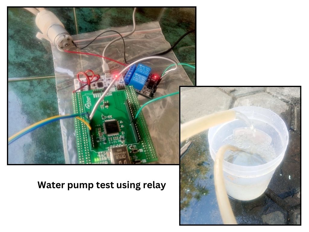
HAL_GPIO_WritePin(GPIOF, GPIO_PIN_9, GPIO_PIN_SET); //or GPIO_PIN_RESETIn the case of arid soil, the pump will be turned on for 10 seconds, and in the case of moist soil, the pump will be turned on for 5 seconds. The control signal will trigger the relay, which is already connected to the water pump, allowing the pump to turn on and off according to instructions from the STM32F722ZE.
Step 5: Make Arduino Shield
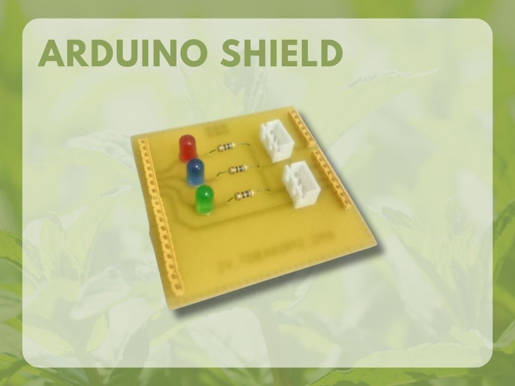
All system functions to be implemented in this project are working well. Next, we will create an Arduino shield. The Arduino shield will assist in the assembly process to make it easier and minimize the use of potentially detached jumper cables. Additionally, LEDs will be added to indicate soil moisture.
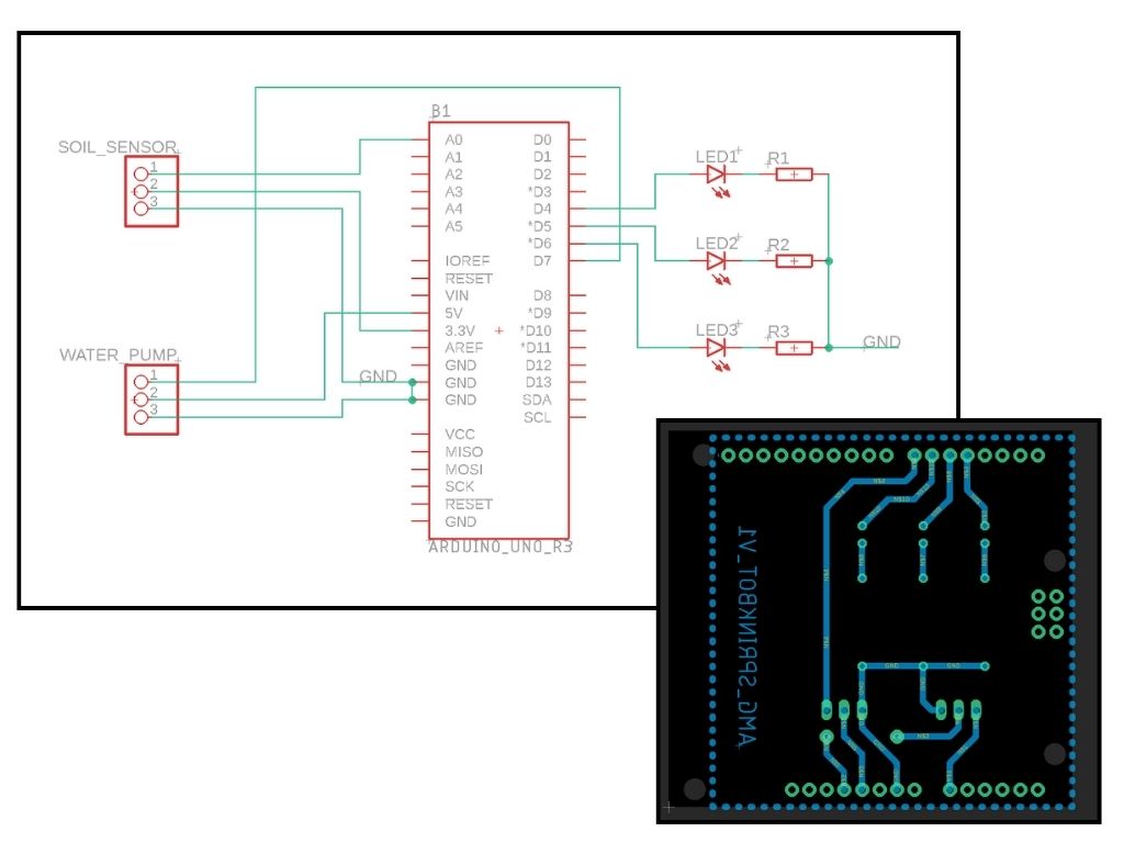
First, we need to create a schematic design for the board. The W5300 used in this project has pins compatible with the Arduino Uno so we will use the schematic of the Arduino Uno. We will design the PCB board once the schematic design process is complete. In this section, components are arranged to ensure a snug and tidy fit to form the shield. During this process, traces are created from one component to another. The resulting board can be seen in the image below.
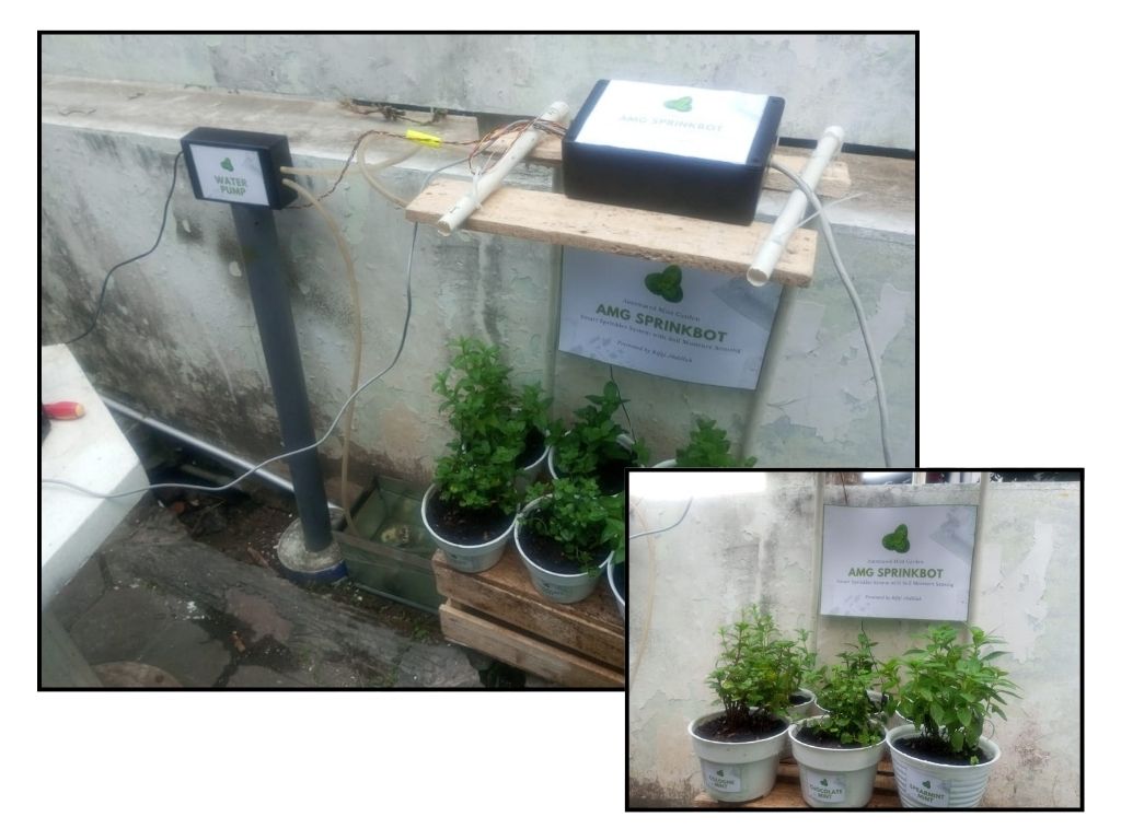
Step 6: Sprinkler System Assembly
Firstly, gather the necessary materials: a hose for water supply, pipes for supporting the irrigation heads, and connectors to join everything together. Ensure you have the right tools like scissors, a hole punch, and some wire. Next, cut the hose to the desired length for water distribution. This hose will be the main channel to carry water from the source to the plants. You can use a sharp pair of scissors to achieve a clean cut.
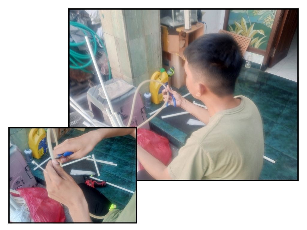
Then, prepare the pipes that will hold the irrigation heads. Measure and cut the pipes to the appropriate lengths, considering the areas you want to water. These pipes will act as the support structure for the sprinklers or drip heads. After that, use a hole punch to create holes in the hose at the locations where you want water to come out. These holes will serve as the outlets for water to reach your plants. Ensure the holes are evenly spaced and positioned according to your plant layout.
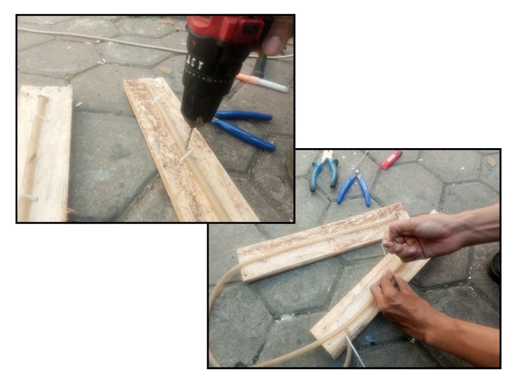
Now, it's time to connect the pipes to the hose. Use connectors that fit the diameter of your hose and pipes. Attach the pipes vertically to the hose, ensuring a secure fit. This way, the pipes will stand like mini sprinkler stands. You can secure the pipes to the ground using wire or stakes to prevent them from tipping over. Wrap the wire around the pipes and push it into the soil to keep the pipes stable.
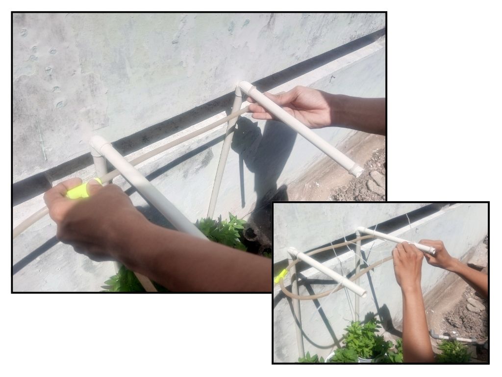
Finally, connect the hose to a water source, like a garden tap or a water reservoir. Turn on the water supply to see if your system is working effectively. Water should flow through the hose, reach the pipes, and then be distributed through the holes to water your plants.
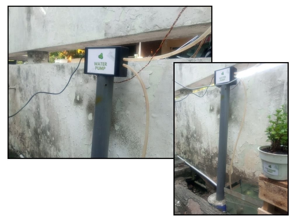
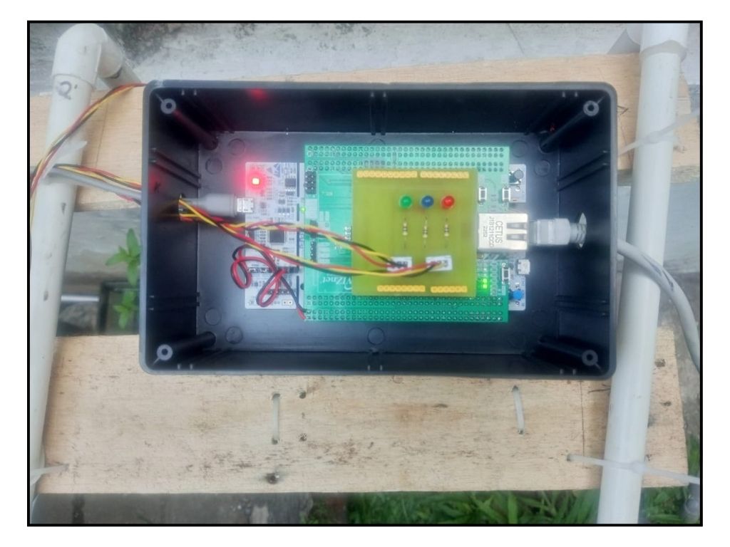
Step 7: Device Test
Closing

In conclusion, this project has presented an opportunity to create an innovative and automated plant irrigation system using advanced technologies. By integrating the STM32F722ZE processor, W5300 Arduino shield, and soil moisture sensors, we aim to achieve a sophisticated, adaptable, and efficient watering solution for mint plants. As we progress with this project, we hope to successfully implement the envisioned functionalities, optimize the system's performance, and demonstrate the positive impact of intelligent irrigation on plant health and resource conservation. Through careful planning, collaboration, and continuous improvement, we aspire to contribute to advancing sustainable agriculture practices and enhance our understanding of smart automation systems in real-world applications.
For Makers, By Makers!
SEE YOU ON THE NEXT PROJECT! :)
-
AMG Sprinkbot Code
All code that used in AMG Sprinkbot

-
AMG Sprinkbot Schematic
All schematic and board that used in AMG Sprinkbot
