
PMI DC BATTERY CHARGER
Battery Charger is thyristor controlled, fully digital, static AC/DC rectifier with constant voltage / constant current characteristic.

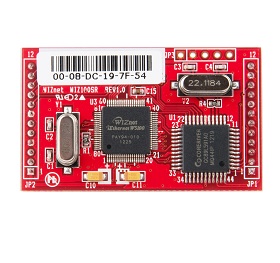
WIZnet - WIZ100SR
x 1
Title
PMI RDAT 3-Phase DC Rectifier / Battery Charger: A SCADA-friendly DC power system with SCR rectification, CC/CV charging, and a WIZnet-based Serial-to-Ethernet (S2E) TCP/IP converter in the comms chain
Introduction
This project is an engineer-oriented walkthrough of PMI’s DC Rectifier / Battery Charger (RDAT), based on the official user manual you provided. The goal is to explain what the unit does (battery charging + DC bus supply), how it’s typically operated in industrial sites, and—most importantly for connected facilities—how its serial-first comms architecture is lifted onto Ethernet. In the manual, PMI explicitly points users to WIZnet’s WIZ1xxSR_config utility when configuring the TCP/IP converter used for TCP/IP, DNP3, and SNMP communication modes—so we can clearly describe where and how WIZnet technology is used inside the overall system design.
Overview
At its core, RDAT is an SCR (thyristor) controlled AC/DC rectifier designed to run an industrial DC bus while charging a battery string using automatic constant-voltage / constant-current (CC/CV) behavior. PMI positions isolation and survivability as key design goals: an input isolation transformer plus a DC current module keep the load isolated and protected even in failure scenarios.
From a power-quality standpoint, the platform offers 6-pulse and 12-pulse configurations; the 12-pulse option is framed around lower harmonic current distortion and better input power factor. The unit also emphasizes low DC ripple (with an output LC filter) as a battery-life lever.
Quick background
In substations, plants, and industrial automation rooms, the DC system is often the “last thing allowed to die.” Trip coils, protection relays, control I/O, and comms gear may all depend on a stable DC bus. That’s why rectifier/chargers like RDAT are evaluated not just on charging performance, but on:
- Isolation and protection behavior under abnormal mains and load conditions
- Operational visibility (alarms, event logging, mimic/MCB state awareness)
- Integration paths to SCADA/PLC networks (contacts + protocol communication)
RDAT’s documentation reflects that mindset: it combines configurable charging modes with both hardwired alarm contacts and interactive serial/network communications that support monitoring and remote control.
What is PMI?

Repo: https://pmienergy.com/about-us-2/
PMI presents itself as an industrial power electronics manufacturer operating with clear separation between Sales & Marketing and a dedicated Manufacturing Plant and R&D site, both listed in the manual. That’s the typical footprint of vendors shipping equipment into infrastructure and process industries where deployment, service, and documentation matter as much as the hardware.
The manual also hints at the product’s “spread” through industrial use cases rather than developer communities: energy distribution facilities, oil & gas sites, mines (security/lighting), and building automation are explicitly called out. In other words, the product’s influence is driven by field adoption and system-integration projects (SCADA/PLC deployments), not by open GitHub-style ecosystems.
Architecture & Data Flow (mechanism-first)
1) Power path
A simplified view of RDAT’s electrical architecture:
- AC input → input isolation transformer → SCR rectifier (6-pulse / 12-pulse) → DC output bus
- Battery string sits on the DC bus to provide ride-through and backup power
- Output LC filter is used to reduce DC ripple (positioned as beneficial for battery life)
2) Control & operations
RDAT is designed to be configured locally (front panel) and supervised remotely. Typical operational knobs include adjusting total output current, battery charge current, float/boost voltages, and enabling “smart boost” and battery test functions. It also supports monitoring of breaker states via auxiliary contacts (a practical detail often missed in “spec sheet” discussions).
3) Communications model: serial-first, then bridged to Ethernet
This is where RDAT becomes very interesting for modern plants.
The manual describes two parallel integration paths:
- Serial communication (interactive monitoring + remote ON/OFF + parameter changes)
- Free alarm contacts (hardwired dry contacts for alarms/status)
For serial communications, PMI lays out a very explicit ladder of connectivity options:
- PC access via RS-485/RS-232 converter
- PLC/Automation via RS-485 Modbus
- Profibus via RS-485/Profibus converter
- Network / SCADA via an RS-485 Modbus → TCP/IP converter chain
This design is common in industrial power gear: keep the device’s native interface robust and serviceable (RS-485), then provide optional “last mile” adapters depending on the customer’s network/protocol requirements.
WIZnet / Ethernet Section (where WIZnet is used, and how)
What WIZnet product family is involved
RDAT’s manual explicitly instructs users to configure the TCP/IP converter using:
WIZ1xxSR_config_v3.0.2_install.zip(from the supplied CD)- or downloads from old.wiznet.co.kr (separate links referenced for TCP/IP+DNP3 and for SNMP)
That naming is a strong indicator that the “TCP/IP converter” in RDAT’s networking path is based on (or is compatible with) WIZnet’s WIZ1xxSR Serial-to-Ethernet (S2E) family—at minimum at the tooling/configuration layer.
Where it sits in the system
In RDAT’s network integration, the WIZnet-based S2E device sits between the charger’s RS-485 world and the plant Ethernet world:
Communication PCB (RDAT) → RS-485 (optional RS-232 conversion) → Modbus/TCP-IP network converter → Ethernet network
What it does (data mechanism)
Mechanically, the WIZnet-based converter acts as the bridge that allows SCADA/PC tools to talk to the charger over Ethernet even though the charger’s native interface is serial:
- The charger exposes measurements, alarms/warnings, and status over the serial side
- The comms system is described as “interactive,” enabling remote ON/OFF and parameter adjustments
- When operating in TCP/IP, DNP3, or SNMP communication types, the software requires the Slave ID (set on the front panel) and the IP address assigned to the converter
In practical engineering terms: RDAT keeps deterministic field wiring and serviceability at RS-485, while the WIZnet S2E converter provides the network “edge” that makes the system routable and manageable on Ethernet—without forcing the rectifier/charger itself to become a full Ethernet endpoint.
Why this approach is attractive in industrial products
Even without marketing language, the documentation reveals a pragmatic product strategy:
- Keep the charger’s internal comms stable and proven (RS-485)
- Offer Ethernet/protocol flexibility as optional external building blocks
- Use widely deployed S2E tooling (WIZnet WIZ1xxSR config utility) to reduce integration friction for installers and service teams
Results / Lessons learned / Limitations
- RDAT is not just a charger—it’s a DC power platform meant to be operated, including remote control and telemetry.
- The manual’s communication section makes it clear that serial + converters are a deliberate architecture choice, not an afterthought.
- The documentation names TCP/IP, DNP3, and SNMP communication types in the PC software workflow, but a full DNP3 point map (objects/events mapping) is not elaborated in the excerpts we relied on; real SCADA projects may still require system-level verification of point definitions and drivers.
Where this matters (who should care)
- Substation, plant, and automation engineers deploying industrial DC systems with batteries
- OT/SCADA integrators who need to connect RS-485 equipment into Ethernet networks while preserving maintainability
- Engineers interested in “real-world” product design patterns: serial core + WIZnet S2E edge is a common and effective approach
Quick Reproduce / Getting Started (field checklist)
1.Decide your integration path: hardwired alarms only, serial, or Ethernet (via converter).
2. For Ethernet/SCADA, wire the chain as documented: Communication PCB → RS-485/RS-232 converter (if needed) → Modbus/TCP-IP converter → Network.
3. In the PC software, choose the communication type:
- RS-485: set Slave ID + COM port
- TCP/IP / DNP3 / SNMP: set Slave ID + converter IP address
4. If the converter’s serial/IP factory settings need changes, configure the TCP/IP converter using WIZnet WIZ1xxSR_config as instructed.
Documents
Documents: http://www.pmigess.com/files/RECT-UM%200618-EN%20RV003ph.pdf
Related VAR UCC
- Anothor Industrial VAR: https://maker.wiznet.io/matthew/resellers/industrial-shields-arduino-plc-for-automation-monitoring-and-control/
- Related Contents (DNP3 UCC): https://maker.wiznet.io/matthew/projects/desenvolvimento%2Dde%2Dum%2Dsistema%2Dde%2Dconverso%2Dentre%2Dos%2Dprotocolos%2Ddnp3%2De%2Dmodbus/
Title
PMI RDAT 3-Phase DC Rectifier / Battery Charger: 산업 현장의 DC 제어전원을 “원격 운영( Modbus/TCP, DNP3, SNMP )”까지 확장하는 방법 — WIZnet WIZ1xxSR 기반 TCP/IP Converter가 들어가는 구조
Introduction
본 프로젝트는 PMI의 DC Rectifier / Battery Charger(RDAT) 사용자 매뉴얼과 제품 소개 페이지를 바탕으로, 이 장비가 배터리 충전 + DC 부하 공급을 어떻게 구현하고, 현장에서 중요한 **원격 모니터링/제어(특히 TCP/IP·DNP3·SNMP)**를 어떤 방식으로 붙이는지 정리한 제품 소개형 큐레이션입니다. 특히 매뉴얼에는 네트워크 통신을 위한 “TCP/IP Converter” 설정 도구로 **WIZnet WIZ1xxSR_config**가 명시되어 있어, “이 제품의 통신 옵션 체인에서 WIZnet이 어디에 쓰였는지”를 메커니즘 관점으로 분명히 설명할 수 있습니다.
접근 가능 여부
PMI 제품 페이지: 검색을 통해 내용 확인 가능(앵커 포함 URL 직접 열람은 일시적 fetch 오류가 있었음)
사용자 매뉴얼 PDF: 첨부본으로 확인 완료
Overview
RDAT는 Thyristor(SCR) 제어 기반 AC/DC 정류기로, 산업용 배터리 운용에 기본이 되는 CC/CV(정전류/정전압) 충전을 전제로 설계된 제품입니다. 단순 충전기가 아니라, 현장에서 흔한 “DC 버스” 환경(보호/제어/신호/차단기 전원 등)을 위해 배터리와 DC 부하를 동시에 책임지는 DC 전원 장치로 소개됩니다.
또 하나의 핵심은 “운영”입니다. RDAT는 알람/상태를 단순 접점으로도 빼고(Free Alarm Contacts), PC/PLC/네트워크 기반으로도 붙일 수 있게 설계돼 있습니다. 이 운영 옵션이 실제 현장 적용에서 제품 가치를 크게 키웁니다.
Quick background
산업 현장에서 DC 전원(정류기+배터리)은 “정전 시에도 멈추면 안 되는” 계통(보호계전, 차단기 트립/클로징, 제어/감시, 통신 장비 등)을 떠받칩니다. 그래서 RDAT류 장비는 **전원 품질(리플/과도응답/보호)**뿐 아니라, 장애 징후를 빨리 잡아내는 이벤트/알람, 그리고 관제 시스템과 붙는 통신이 함께 요구됩니다.
Author & Community (이 회사는 누구이고, 어디서 파급력이 있나)
PMI(문서상 Power Management Instruments 및 그룹사 표기)는 제조 플랜트와 R&D 조직 주소를 별도로 표기할 정도로 “산업 장비 제조+개발” 성격이 뚜렷합니다. 제품군도 UPS/정류기/충전기 등 전력전자 장비 중심으로 전개되는 것으로 소개됩니다.
파급력은 개발자 커뮤니티형(오픈소스 중심)이라기보다는, 전력·오일&가스·광산·빌딩 자동화 같은 산업 도메인에서 “현장 채택”을 통해 확산되는 타입에 가깝습니다. 실제로 동일/유사 제품 정보가 산업 카탈로그 플랫폼(예: DirectIndustry)에도 올라가 있어, 구매/견적 흐름에서 노출되는 경로를 갖고 있습니다.
Architecture & Data Flow (메커니즘)
1) Power path: AC → DC, 배터리+부하 동시 운용
토폴로지: Thyristor controlled AC/DC rectifier + 입력 절연 변압기(갈바닉 절연)
충전 원리: Constant Current / Constant Voltage (CC/CV)
6/12 pulse 옵션: 12 pulse에서 THDi 저감, 입력 PF 개선을 명시
출력 품질: **Output ripple < 1%**를 목표로 하며, 문서에서는 LC 필터 기반 저리플이 배터리 수명에 유리하다고 설명합니다.
2) 운영/보호: “고장 나기 전에 잡는” 설계
과전류/단락/과온 등 보호와 함께, 운전 상태(라인/배터리/부하 MCB 등)를 표시/감시하는 구성이 설명됩니다.
이벤트/알람은 **접점(Free alarm contacts)**과 통신(시리얼/네트워크) 두 경로로 상위 시스템에 전달될 수 있습니다.
3) 통신/SCADA 데이터 흐름: RDAT의 차별점이 드러나는 부분
RDAT 매뉴얼이 제시하는 통신 그림은 매우 실전적입니다. 장비가 가진 내부 데이터/상태를 “현장 장비 친화적인 시리얼(주로 RS-485)”로 먼저 뽑고, 필요하면 이를 네트워크로 올리는 방식입니다.
RDAT(Communication PCB)
→ RS-485/RS-232 Converter(필요 시)
→ Modbus/TCP-IP Converter
→ Network(PC/SCADA/Automation)
이 구조는 “제품 본체는 현장 검증된 RS-485 계열 통신을 유지하면서, 네트워크 요구(TCP/IP·DNP3·SNMP)는 옵션 블록으로 확장”하기에 좋습니다.
WIZnet / Ethernet Section (WIZnet이 실제로 어디에 쓰였나)
어떤 WIZnet 제품이 쓰였나
RDAT 매뉴얼은 TCP/IP·DNP3·SNMP 통신 설정을 설명하면서, 컨버터 설정 인터페이스로 **WIZ1xxSR_config_v3.0.2_install.zip**를 사용하라고 명시합니다.
즉 RDAT의 네트워크 통신 옵션에서 말하는 “TCP/IP Converter”는 WIZnet WIZ1xxSR(Serial-to-Ethernet, S2E) 계열을 전제로 한 구성임을 문서 수준에서 확인할 수 있습니다(최소한 설정 툴과 다운로드 링크가 WIZnet 리소스를 가리킵니다).
어디에 들어가고(위치), 무엇을 하며(역할), 어떤 데이터가 오가나(메커니즘)
RDAT의 네트워크 통신은 “WIZnet이 장비 내부에서 모든 프로토콜을 처리한다”기보다는, 시리얼 기반 장비 데이터를 Ethernet 세상으로 ‘올려주는’ 브리지 역할에 가깝습니다.
RDAT 내부에서 나오는 RS-485 기반 데이터(측정값/상태/알람/설정)
→ WIZnet 기반 TCP/IP Converter(S2E)로 들어가며
→ 네트워크에서는 “소프트웨어가 선택한 통신 타입”에 따라 접근합니다.
RS-485 방식이면: Slave ID + PC의 COM 포트
TCP/IP·DNP3·SNMP 방식이면: Slave ID + Converter IP(및 포트 개념)
즉 **RDAT는 ‘현장 시리얼’에 강하고, WIZnet S2E가 ‘Ethernet으로 확장’**을 담당하는 형태입니다. 운영자가 실제로 손대는 포인트도 딱 그 지점(Converter IP/Serial 설정)이며, 매뉴얼이 바로 그 설정 도구로 WIZ1xxSR_config를 지정합니다.
왜 WIZnet 방식이 채택되기 쉬운가
이 설계가 실무적으로 좋은 이유는 명확합니다. 제조사 관점에서 네트워크 스택을 장비 본체에 깊게 내장하는 대신, 검증된 S2E(TCP/IP Converter) 블록으로 옵션을 구성하면
제품 본체(전력/충전 제어)의 안정성을 흔들지 않고,
고객/현장마다 달라지는 네트워크 요구(TCP/IP, DNP3, SNMP)를 빠르게 대응할 수 있습니다.
RDAT 매뉴얼에서 “TCP/IP Converter의 IP/시리얼 포트 기본값을 바꿀 때 WIZnet 설정 툴을 사용하라”고 딱 짚는 것도, 이 옵션 블록이 실제 납품/운영 단계에서 중요하다는 뜻입니다.
Results / Lessons learned / Limitations
RDAT류 제품은 “전원을 만든다”에서 끝나지 않습니다. 원격에서 켜고/끄고, 값을 보고, 알람을 수집하고, 설정을 바꾸는 운영 능력이 제품 경쟁력의 큰 축입니다.
RDAT 매뉴얼은 Modbus 데이터 테이블(설정/상태/이벤트 코드)을 제공해, 통신이 단순 모니터링을 넘어 “운영 인터페이스”임을 분명히 합니다.
한계: 본문은 제공된 매뉴얼 범위에 근거해 설명했으며, 프로젝트별로 DNP3 포인트 맵/시스템 통합 방식은 추가 확인이 필요할 수 있습니다(현장 SCADA 구성에 따라 달라짐).
Where this matters (누가 보면 좋은가)
변전소/플랜트/광산/빌딩 자동화 등에서 **DC 버스(배터리+정류기)**를 운영하는 엔지니어
RS-485 장비를 TCP/IP·DNP3 기반 SCADA로 묶어야 하는 OT/SCADA 통합 담당자
“산업 장비에서 WIZnet S2E가 실제 제품 체인에 어떻게 들어가는지”를 보고 싶은 메이커/개발자
Quick Reproduce / Getting Started
운영 환경에서 통신 방식을 먼저 확정합니다: RS-485(Modbus) vs 네트워크(TCP/IP·DNP3·SNMP)
네트워크형이라면, RDAT 매뉴얼의 구성도처럼 “RS-485 → TCP/IP Converter → Network” 체인으로 구성합니다.
소프트웨어 설정에서
RS-485: Slave ID + COM 포트
TCP/IP·DNP3·SNMP: Slave ID + Converter IP
Converter의 IP/시리얼 기본값을 바꿔야 한다면, 매뉴얼이 지정한 **WIZnet WIZ1xxSR_config**로 설정합니다.
WIZnet 관점
오래된 제품을 사용하고 있으며, 현재 판매중이고, 대체품인 ioNIC (W55RP20 S2E)가 타겟할 수 있는 VAR 제품입니다.
이 매뉴얼에서 확인되는 구조는 “RS-485 기반 장비 + 외장형 TCP/IP Converter” 방식입니다.
또한 DNP3의 경우 현재도 많이 사용되고 있는 큰 시장입니다.
따라서 시장성이 있는 곳의 실제 판매되는 제품이므로 현재 WIZnet의 다른 제품(W55RP20 시리즈)으로 대체를 제안하고 커스텀 솔루션까지 제공하면, 고객과 WIZnet 모두 좋을 것이라 생각됩니다.
References
PMI Energy — DC Battery Charger 제품 소개 페이지 pmienergy.com
DirectIndustry — PMI/OES Group “Floor-standing battery charger” 제품 설명(Scada-ready, Modbus RS-485/TCP 등) DirectIndustry
DirectIndustry PDF Catalog — “Battery Charger / DC Rectifier”(RDAT series, THDi/PF 등) Directindustry
PMI DC Rectifier / Battery Charger User Manual (RECT-UM 0618-EN RV00) — 통신 옵션 개요/구성도/Free contacts/Modbus 테이블/WIZnet 설정툴 명시
Documents: http://www.pmigess.com/files/RECT-UM%200618-EN%20RV003ph.pdf
PMI Energy — R&D 소개(소프트웨어/하드웨어 엔지니어 포함, 전력전자 장비 포트폴리오) pmienergy.com
Documents: http://www.pmigess.com/files/RECT-UM%200618-EN%20RV003ph.pdf
Anothor DNP3 VAR: https://maker.wiznet.io/matthew/resellers/industrial-shields-arduino-plc-for-automation-monitoring-and-control/
Related Contents (DNP3 UCC): https://maker.wiznet.io/matthew/projects/desenvolvimento%2Dde%2Dum%2Dsistema%2Dde%2Dconverso%2Dentre%2Dos%2Dprotocolos%2Ddnp3%2De%2Dmodbus/