
W5300-MQTT-Cam: Vision-based IoT with MQTT & HTTP Access
An IoT solution utilizing W5300-TOE-Shield for capturing images, accessible via MQTT & HTTP.


OpenMV - OpenMV Cam H7
x 1
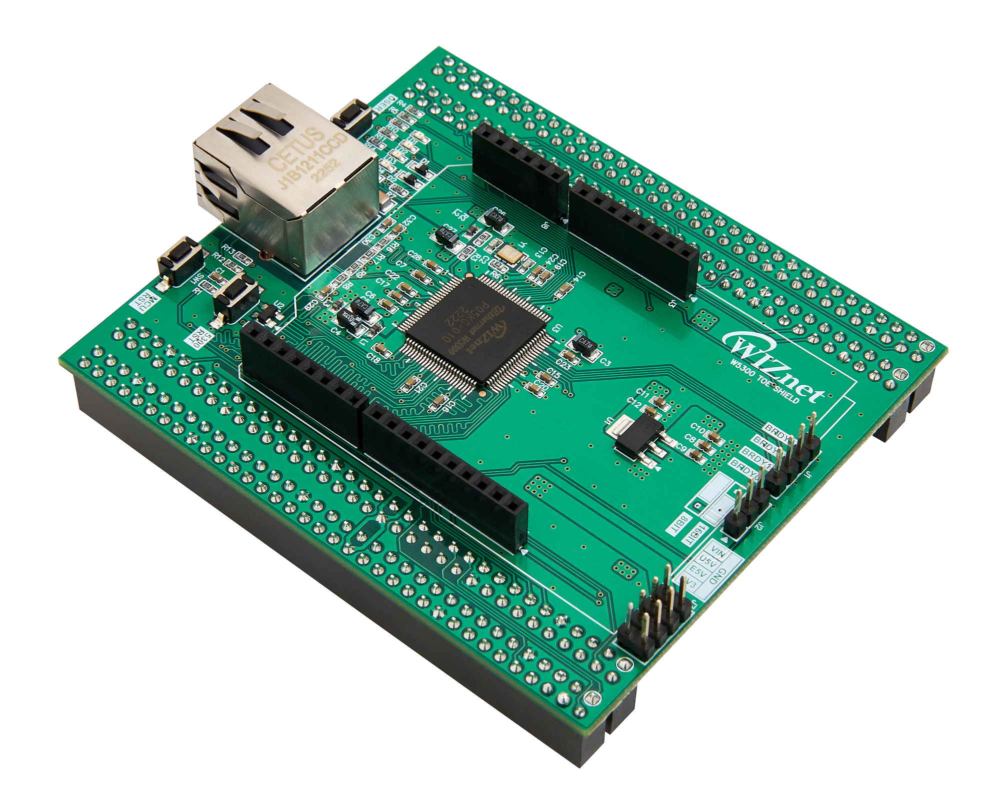
WIZnet - W5300-TOE-Shield
x 1
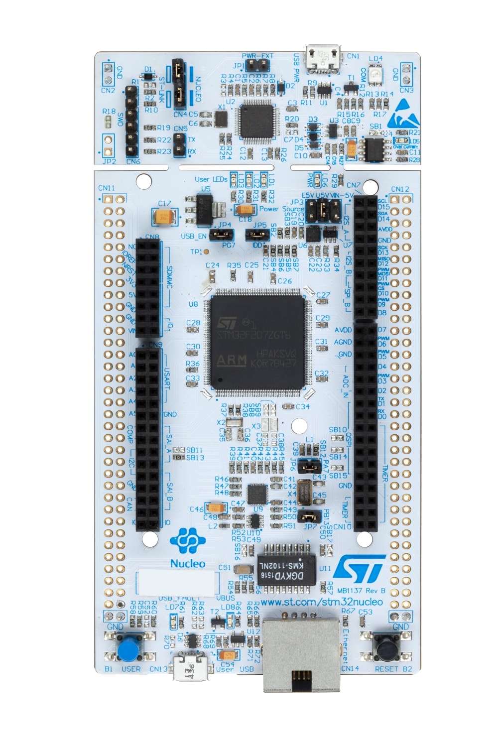
ST - NUCLEO-F429ZI
x 1
Eclipse - Paho MQTT
x 1
Android - Android Studio
x 1

Arduino - Arduino IDE
x 1
PyCharm - Pycharm
x 1
Introduction:
The digital era has seen an explosive growth of IoT devices, but the integration of vision applications within IoT frameworks remains underexplored. The W5300-MQTT-Cam project is a pioneering step into this frontier, binding the power of vision applications to IoT devices. Utilizing the prowess of the W5300-TOE-Shield, this project not only enables the capture of images but also their dissemination and access via established protocols like MQTT and HTTP. Such integrations point to a future where vision-enabled IoT devices can be implemented across numerous industries, changing the way we perceive and utilize IoT.
Implementation and Operation:
WIZnet W5300-TOE-Shield: This module is intricately connected to the STM32 Nucleo-144 (F429ZI) boards, acting as the linchpin for internet connectivity. With its high-speed data transmission capability, the shield ensures real-time or near-real-time transmission of images, depending on the chosen resolution.
OpenMV H7 Camera Module: Integrated with the STM32 Nucleo-144 board, the OpenMV camera module captures high-quality images on command. The communication protocol established through the serial port ensures a seamless transfer of image data.
Flask Web Service: As a lightweight yet robust web framework, Flask handles the image reception using the POST method. Once the image is uploaded, it is stored and an HTTP URL is generated. This URL offers a direct path for any internet-connected device to access the image.
MQTT Broker: The choice of MQTT is deliberate, given its lightweight nature and ability to facilitate communication between a myriad of devices with minimal overhead. The broker effectively handles the communication requests from the Android app and directs the STM32 board to activate the OpenMV camera module.
Android App: The user-friendly interface allows users to send camera capture commands and view the resultant images. This immediate feedback loop ensures that users can take corrective actions, like adjusting the camera angle or settings, if necessary.

Creativity and Reusability:
The brilliance of the W5300-MQTT-Cam project lies not just in its innovative combination of vision and IoT, but also in its modular design. Each component, from the WIZnet shield to the Flask service, can be repurposed or extended for diverse applications. For instance, while the current focus is on image capture, the same framework can be extended to video capture, or integrating sensors to capture environmental data alongside images. This inherent reusability makes the project a valuable asset for developers and industries alike.
Use Cases & Applications:
Home Security: The setup can be repurposed as a security camera where homeowners can remotely capture images of their premises to check on safety or to verify visitor identities.
Industrial Monitoring: In industrial setups, real-time monitoring of machinery or processes is crucial. Our system can be implemented to capture images of machine operations, ensuring everything runs smoothly.
Agricultural Automation: Farmers can use the device to monitor crops or livestock. The real-time image capture can help in identifying issues like crop diseases or pest infestations.
Retail: In retail spaces, the setup can be employed to monitor customer footfalls, helping store owners to optimize space and product placements.
Environment Monitoring: By pairing with environmental sensors, images can be captured alongside data like temperature or humidity, providing a more comprehensive view of a location.
Demo Video
Getting started!
Arduino environment
To configure Arduino environment for STM32 Nucleo-144 (F429ZI), you need to follow the instructions of WIZnet official website.
OpenMV Camera environment
To configure OpenMV environment, you need to follow the instructions of OpenMV official website.
Flask web application environment
To configure and run the Flask web server, follow these steps:
Environment Setup:
- Ensure you have Python installed on your system.
- Create a virtual environment to manage dependencies. This is optional but recommended to avoid any conflicts with other Python projects:
python -m venv venv_name
source venv_name/bin/activate  # On Windows: .\venv_name\Scripts\activate
Install Necessary Libraries:
- Navigate to the directory containing your Python script and install the required libraries:
pip install flask influxdb influxdb-client
Directory Structure:
- Create a directory named
imagesin the same location as your Python script. This is where uploaded images will be stored. - If you have an
index.htmlfile (as referenced in the code), ensure it's located within atemplatesdirectory in the same location as your Python script.
InfluxDB Setup:
- The code sis using InfluxDB. Ensure that InfluxDB is installed and running on your system.
- The code references a module
InfluxDB_v1, so make sure this module is present in your project directory or is available in your Python path. - Update any necessary configurations for InfluxDB, such as database credentials, within the
InfluxDB_v1module or directly in your main script.
Run the Flask Application:
- Set the Flask environment variables and run the application:
export FLASK_APP=ImageUploader1.py
export FLASK_ENV=development
flask run --host=0.0.0.0
Access and Test the Web Server:
- Once the Flask server is running, navigate to
http://127.0.0.1:5000/in your browser. - Use the interface (if available) or a tool like
curlor Postman to POST an image to the/uploadroute and test the image uploading functionality.
Android app environment
Configuration Steps for W5300-MQTT-Cam Android App:
Development Environment Setup:
- If not already done, install Android Studio and open it.
- Import the provided Android project.
Add Necessary Dependencies:
- Since this app uses the HiveMQ MQTT client, ensure you have the required dependency in the
build.gradle(Module: app) file:
implementation 'com.hivemq:hivemq-mqtt-client:1.2.1'MQTT Broker Configuration:
- In
MainActivity.kt, locate the line:
val mqttBroker = "44.195.202.69"
- If you have a different MQTT broker address, update this line accordingly.
UI Configuration:
- Check the
activity_main.xmllayout file (located in theres/layoutdirectory) to ensure all UI elements are properly defined and styled. - If you want to customize the UI, make the necessary modifications in this XML file.
Network Permissions:
- Ensure the app has permissions to access the internet and netwrk state. In the
AndroidManifest.xmlfile, verify the inclusion of:
<uses-permission android:name="android.permission.INTERNET" />
<uses-permission android:name="android.permission.ACCESS_NETWORK_STATE" />
Functionality:
- In
MainActivity.kt, ensure that the MQTT client is correctly set up to send the "cmd:capture" command upon a specific user action (like pressing a button). - Check the logic that handles the reception of the image URL and its display in the WebView.
Testing:
- Run the app on an Android emulator or a physical device.
- Use the app interface to send the "cmd:capture" command.
- Verify that the app correctly displays the captured image URL or the image itself in the WebView.
Deployment:
- Once you've tested the app and ensured it works as expected, you can prepare it for release. Build a signed APK or App Bundle through Android Studio, and then distribute it via the Google Play Store or other methods.
H/W configuration
Circuit Diagram

Hardware Configuration for OpenMV Camera Module and STM32 Nucleo-144 Board:
Prepare Both Modules:
- Ensure both the STM32 Nucleo-144 board and the OpenMV camera module are powered off to prevent any accidental shorts or damage.
- Lay out both modules on a non-conductive surface.
Serial Connection:
- Connect the TX pin (pin 1) of the STM32 Nucleo-144 board to the UART3_RX (P5) pin of the OpenMV camera module. This will allow the Nucleo-144 board to transmit data which the OpenMV camera module will receive.
- Connect the RX pin (pin 0) of the STM32 Nucleo-144 board to the UART3_TX (P4) pin of the OpenMV camera module. This setup ensures the Nucleo-144 board can receive data transmitted by the OpenMV camera module.
Power Connection:
- Connect the GND (Ground) pin of the OpenMV camera module to the GND pin of the STM32 Nucleo-144 board. This establishes a common ground between the two devices.
- Connect the VCC pin of the OpenMV camera module to the VCC (or an appropriate power supply pin, depending on the voltage requirements of the OpenMV) pin of the STM32 Nucleo-144 board. This will power the camera module.
Source codes
Arduino (W5300-MQTT-CAM2.ino) Code explanations
Function: client_write_large(byte *bptr, size_t len)
- Purpose: This function is designed to handle the sending of large data segments over the Ethernet client. Given the constraints of the W5300-TOE-Shield's buffer size and the potential size of image data from the OpenMV camera, this function is crucial for ensuring data is sent efficiently and without overflow.
- Parameters:
byte *bptr: A pointer to the byte array that contains the data to be sent.size_t len: The total length of the data in the byte array.
- Functionality:
- The function breaks the data into smaller chunks of size
max_transferand sends each chunk separately. This segmented approach ensures that the W5300-TOE-Shield's buffer is not overwhelmed. - For each segment, the function updates the pointer (
bptr) to point to the next chunk of data and adjusts the sent data's size. - Once all large chunks are sent, any remaining data that is less than
max_transferin size is sent. - For debugging purposes, the function prints the total sent data's size.
- The function breaks the data into smaller chunks of size
Function: void httpPostForm(byte *imageData, uint32_t imageSize)
- Purpose: This function is designed to send a POST request containing both text and image data to an HTTP server. It sets up the POST request headers and body in accordance with the
multipart/form-dataformat. - Parameters:
byte *imageData: A pointer to the byte array containing the image data to be sent.uint32_t imageSize: The size of the image data in bytes.
- Functionality:
- Initially, the function sets a string variable
textDatawith the value "OpenMVCam1". This represents textual data that will be sent along with the image. - The function then constructs the request body. It first appends the textual data using the boundary "ArduinoBoundary_OpenMVCam1" and then prepares to append the image data.
- The image data is associated with the format "image" and is named "image.jpg".
- After the image data, a closing boundary is appended to signify the end of the
multipart/form-data. - The function then constructs the request headers. It specifies the POST method, the host to which the request is being sent, the content type, and the total content length. The content length accounts for the lengths of the request body, the image data, and the closing boundary.
- Once the headers and body are prepared, the function sends the headers, followed by the request body, using the client object. It ensures all data is sent and flushes any remaining data.
- The function leverages the previously defined
client_write_largefunction to send the large image data in chunks. - Finally, a delay is introduced to ensure the entire POST request is processed properly.
- Initially, the function sets a string variable
The httpPostForm function encapsulates the process of sending the captured image data to an HTTP server, showcasing the ability of the STM32 Nucleo-144 board to not only capture images via the OpenMV camera but also transmit them to a server for further processing or storage.
Function: void http_postData(byte *buf, uint32_t length)
- Purpose: This function manages the HTTP POST request process, ensuring a stable connection to the server, sending the image data, and handling the server's response.
- Parameters:
byte *buf: A pointer to the byte array containing the data to be sent in the POST request.uint32_t length: The size of the data in bytes.
- Functionality:
- The function initializes a
countvariable to zero. This variable tracks connection retry attempts. - If the client is not connected to the server, it attempts to reconnect. If the connection fails after five retries, the function exits, indicating a failure to post data.
- After ensuring a connection, the function calls the
httpPostFormfunction, which constructs and sends the POST request with the specified image data. - Once the data is sent, the function waits for a response from the server. It determines the length of the response and attempts to read it into a buffer.
- The received data is processed to extract the server's response content. This involves iterating through the buffer to find the start of the content (usually after two newline characters in sequence) and then appending the rest to the
responsestring. - The response content is then printed to the serial output for debugging and published to the "W5300-MQTT" topic.
- Finally, the function closes the client connection.
- The function initializes a
This http_postData function highlights the end-to-end process of sending a POST request to an HTTP server and handling its response. It ensures robustness by managing reconnection attempts and processing the server's response.
Function: void callback(char* topic, byte* payload, unsigned int length)
- Purpose: This function is the callback that gets invoked when a new MQTT message arrives on a subscribed topic. It processes the received payload and takes appropriate actions based on the content of the message.
- Parameters:
char* topic: The MQTT topic on which the message was received.byte* payload: A pointer to the byte array containing the actual message data.unsigned int length: The length of the received message.
- Functionality:
- The function starts by printing the topic on which the message was received, primarily for debugging purposes.
- It then constructs a
cmdstring from the received payload by iterating through the byte array and appending each character to thecmdstring. - After constructing the
cmdstring, the function checks if its value is "cmd:capture".- If the
cmdstring has the value "cmd:capture", it sets thecapture_requestedvariable to 1, indicating that an image capture has been requested. This variable is checked in the main loop to trigger the image capture process. - The function then prints "Capture requested!!!" to the serial output for debugging.
- If the
This callback function plays a pivotal role in the MQTT communication setup. When an external entity wants the STM32 Nucleo-144 board to capture an image using the OpenMV camera, it can send an MQTT message with the payload "cmd:capture" to the board. Upon receiving this message, the board prepares to capture and send the image as previously described.
Function: void reconnect()
- Purpose: This function attempts to reconnect the board to the MQTT broker if it gets disconnected. It is vital for ensuring a persistent and stable MQTT connection, enabling the board to continuously receive commands and send updates.
- Functionality:
- The function enters a loop that continues until a successful connection to the MQTT broker is established.
- Within the loop, the function attempts to connect to the MQTT broker using the unique device ID (
device_unique_id) as the client identifier. - If the connection is successful, it prints a debug message indicating a successful connection.
- The board then publishes a "Ready" message to the "W5300-MQTT" topic. This can serve as an initialization or handshake message, notifying other entities that the board is online and ready to receive commands.
- Subsequently, the board subscribes to the "MQTT-W5300" topic, ensuring it can receive MQTT messages on this topic.
- If the connection attempt fails, the function prints a debug message indicating the failure reason (
mqtt_client.state()) and waits for 2 seconds before retrying.
- Within the loop, the function attempts to connect to the MQTT broker using the unique device ID (
- The function enters a loop that continues until a successful connection to the MQTT broker is established.
The reconnect function is a critical component for ensuring uninterrupted MQTT communication. If the board loses its connection to the MQTT broker, this function makes continuous attempts to re-establish the connection, ensuring that the board remains responsive to MQTT commands and can send data whenever needed.
Function: void setup()
- Purpose: The
setupfunction is a standard Arduino function that initializes settings and configurations when the Arduino starts. It sets up the necessary hardware interfaces and configurations for the board to function properly. - Functionality:
Serial Communication Setup for W5300-TOE-Shield:
- The RX and TX pins for serial communication with the W5300-TOE-Shield are set to PC11 and PC10 respectively.
- A short delay is introduced to ensure the serial port is ready for use.
Serial Communication Setup for OpenMV Camera:
- The RX and TX pins for serial communication with the OpenMV camera are set to 0 and 1 respectively.
- Serial communication is initialized with a baud rate of 500000.
- There's a loop that waits for the serial port (for the OpenMV camera) to connect. This loop ensures that subsequent code doesn't execute until a connection is established.
Ethernet Connection Initialization:
- The code prints a debug message indicating the initiation of the Ethernet connection using DHCP.
- If the Ethernet connection fails using DHCP, a series of checks are performed:
- Check if the Ethernet hardware is present. If not, the code enters an infinite loop, effectively halting the program.
- Check if the Ethernet link is active. If the link is off, a debug message is printed.
- If DHCP fails, the Ethernet connection is attempted with a static IP address.
- If DHCP succeeds, the assigned IP address is printed for debugging purposes.
- A delay ensures the Ethernet shield has time to initialize.
MQTT Configuration:
- The MQTT server's details are set using the
mqtt_client.setServermethod. The server's IP address and port (1883, the standard MQTT port) are specified. - The MQTT callback function (
callback) is set. This function will be invoked when a new MQTT message arrives on a subscribed topic. - A delay ensures all initializations have time to settle before the main loop starts executing.
The setup function is critical for ensuring that the board is correctly initialized and ready to handle its main tasks. It sets up the communication links, connects to the network, and configures the MQTT client for incoming and outgoing messages.
Function: void loop()
- Purpose: The
loopfunction is a standard Arduino function that contains the main repetitive tasks the board should perform. It manages MQTT communications, checks for capture requests, interfaces with the OpenMV camera, and handles data transmissions. - Functionality:
MQTT Communication:
- If the board is not connected to the MQTT broker, the
reconnectfunction is invoked to attempt a reconnection. - The
mqtt_client.loop()function is called to handle any MQTT-related tasks, such as reconnections, incoming messages, and keeping the connection alive.
Image Capture Request Handling:
- If the
capture_requestedvariable is set (which will be set by the MQTT callback function when a capture request is received), the board initiates the image capture process. - The serial buffer is flushed to remove any stale or unwanted data.
- A synchronization code ('0x96') is sent to the OpenMV camera over the serial port to signal an image capture request.
Receiving Image Data from OpenMV Camera:
- The board then waits for a response from the OpenMV camera, which contains the length of the captured image data.
- If a valid length is received, the board proceeds to read the image data from the camera into a buffer (
img_buf). - If the amount of data received does not match the expected length, a time-out error is assumed, and an error message is published to the "W5300-MQTT" topic.
Sending Image Data to HTTP Server:
- If the image data is successfully received, the board sends it to an HTTP server using the previously defined
http_postDatafunction. - Any server responses or errors are handled accordingly and can be published to the MQTT topic for feedback.
Error Handling:
- If no valid data length is received from the OpenMV camera, an error message ("No data") is published to the "W5300-MQTT" topic.
The loop function serves as the heart of the Arduino code. It continuously checks for MQTT messages, processes image capture requests, and handles data transmissions, ensuring that the STM32 Nucleo-144 board remains responsive and functional.
Function: uint32_t serial_read_length()
- Purpose: This function reads the length of the image data from the OpenMV camera. The length is expected to be sent as a 4-byte integer in big-endian format over the primary serial port.
- Return Value: A 32-bit unsigned integer representing the length of the image data.
- Functionality:
Variable Initialization:
- The function initializes a
lengthvariable to store the final length of the image data. - A byte array
recvof size 4 is initialized to store the individual bytes of the length data. - An index variable helps track the position in the
recvarray.
Timeout Configuration:
- A
prevmillisvariable captures the current time in milliseconds. - The function then enters a loop with a timeout of 1 second. This loop continues until either the full length data is received or the timeout is reached.
Reading Length Data:
- Within the loop, the function checks if any data is available on the serial port.
- If data is available, it reads one byte at a time and stores it in the
recvarray. - Once all 4 bytes are received, the function constructs the final length value by combining the bytes in big-endian format.
- The loop is then exited, and the function returns the calculated length.
This serial_read_length function facilitates the communication between the STM32 Nucleo-144 board and the OpenMV camera, enabling the board to determine the size of the incoming image data.
Function: uint32_t serial_read_data(byte *buf, uint32_t length)
- Purpose: This function is tasked with reading the image data sent by the OpenMV camera over the primary serial port. To accommodate large image data, the function reads the data in chunks and stores it in the provided buffer.
- Parameters:
byte *buf: A pointer to the byte array where the image data should be stored.uint32_t length: The expected size of the image data in bytes.
- Return Value: The actual number of bytes read from the serial port.
- Functionality:
Initialization:
- The function initializes the
indexvariable to keep track of the position in the buffer. maxsizeis set to 1024, defining the maximum chunk size for reading data.recvlentracks the number of bytes read in each chunk, andremainkeeps track of the remaining bytes to be read.
Timeout Configuration:
- A
prevmillisvariable captures the current time in milliseconds. - The function enters a loop with a timeout of 2 seconds. This loop continues until either all expected data is received or the timeout is reached.
Chunked Data Reading:
- Inside the loop, the function checks if the remaining data to be read is greater than
maxsize. - If so, it calls the
serial_read_data0function to read a chunk of sizemaxsize. - Otherwise, it reads a chunk equal to the remaining data size.
- If an error occurs during the read (indicated by
recvlenbeing -1), the function exits early and returns the number of bytes successfully read. - After each successful read, the buffer pointer is moved forward by the number of bytes read (
recvlen), and the remaining data size (remain) is decremented.
Return Value Calculation:
- At the end of the function, it returns the total number of bytes read, which is calculated as the initial expected length minus the remaining bytes.
This serial_read_data function ensures efficient and segmented reading of large image data from the OpenMV camera. It leverages another function, serial_read_data0, for the actual data reading.
Function: uint32_t serial_read_data0(byte *buf, uint32_t length)
- Purpose: This function reads a specified number of bytes from the primary serial port (where the OpenMV camera is connected) and stores it in the provided buffer. It's a helper function for the
serial_read_datafunction, focusing on reading individual chunks of data. - Parameters:
byte *buf: A pointer to the byte array where the data should be stored.uint32_t length: The expected number of bytes to be read from the serial port.
- Return Value: The actual number of bytes read. If a timeout occurs, it returns -1.
- Functionality:
Initialization:
- The function initializes an
indexvariable to track the position in the buffer.
Timeout Configuration:
- A
prevmillisvariable captures the current time in milliseconds. - The function enters a loop with a timeout of 1 second. This loop continues until either all expected data is read or the timeout is reached.
Data Reading:
- The function continuously checks if data is available on the serial port.
- If data is available, it reads the byte and stores it in the buffer.
- The buffer index (
index) is incremented with each read. - If the function reads the expected number of bytes (
length), it exits the loop and returns the number of bytes read.
Timeout Handling:
- If the function exits the loop without reading the expected number of bytes, it returns -1 to indicate a timeout or error.
The serial_read_data0 function is crucial for ensuring efficient and error-tolerant data reading from the OpenMV camera. By managing timeouts and chunked data reading, it offers a robust mechanism to retrieve image data for further processing or transmission.
OpenMV Code explanations
Imports:
import sensor, image, time, struct:- These modules facilitate image capture, time management, and data structure manipulation within the OpenMV environment.
from pyb import UART:- Enables serial communication between the OpenMV camera and the STM32 Nucleo-144 board.
Camera Configuration:
sensor.reset(): Resets the camera to default, ensuring a clean start.sensor.set_pixformat(sensor.RGB565): Sets the pixel format, which determines the colors and depth of the captured image.sensor.set_framesize(sensor.QVGA): Configures the resolution of the image to QVGA (320x240 pixels).sensor.skip_frames(time = 2000): Allows the camera to stabilize by capturing and discarding frames for 2 seconds. This step is essential to ensure clear images post-initialization.
UART Configuration for Communication with STM32 Nucleo-144 board:
uart = UART(3, 500000):- Establishes a UART communication channel on UART port 3 at a baud rate of 500,000. This setup allows the OpenMV camera to listen for commands from the STM32 Nucleo-144 board and send data back.
Continuous Monitoring and Image Capture Loop:
while(True):- An endless loop that keeps the OpenMV camera continuously active and responsive to the STM32 Nucleo-144 board's requests.
if uart.any():- Listens for any incoming data on the UART from the STM32 Nucleo-144 board.
ret = uart.read(1): Reads one byte of data, which could be a command or a part of a longer message.if ret[0] == 0x96:- Recognizes the synchronization byte (
0x96). This byte is essentially a command from the STM32 Nucleo-144 board, signaling the OpenMV camera to capture an image. - Image Capture and Transmission:
img = sensor.snapshot(): Captures an image.img.to_jpeg(): Converts the raw image to a more compact JPEG format, suitable for transmission.length = img.size(): Determines the size of the JPEG image in bytes.lenstr = struct.pack('>I', length): Packages the size data into a 4-byte format (big endian), which will likely be sent first to the STM32 Nucleo-144 board to inform it of the incoming image data's size.imgbuf = img.bytearray(): Prepares the JPEG image for transmission by converting it into a byte array.
- Recognizes the synchronization byte (
Sending Image Metadata and Image Data to STM32 Nucleo-144 board:
Send Image Length:
print(lenstr): Outputs the 4-byte representation of the image size, for debugging purposes.uart.write(lenstr): Sends the 4-byte image length to the STM32 Nucleo-144 board over UART. This informs the board of how much data it should expect when the actual image is transmitted.time.sleep_ms(100): Introduces a short delay to ensure the image length data is received by the board before the image data is sent.
Chunked Image Transmission:
- The code then proceeds to send the image data in chunks to better manage the transmission of potentially large image data over UART.
start = 0: Initializes the starting index for the chunked data transmission.maxsize = 1024: Sets the maximum chunk size to 1024 bytes. This determines how much image data will be sent in a single transmission.while length > 0: Continues sending chunks until all image data is transmitted.- Within the loop, the code checks if the remaining image data is less than or equal to the maximum chunk size (
maxsize). If so, it sends the remaining data. Otherwise, it sends a chunk of sizemaxsize. - The
sentvariable captures how many bytes were successfully transmitted in the last operation. - The
startandlengthvariables are updated to track the position in the image buffer and the remaining data to be sent. - The commented-out
time.sleep_ms(1)could have been used to introduce a delay between chunks, ensuring reliable data transmission.
- Within the loop, the code checks if the remaining image data is less than or equal to the maximum chunk size (
This chunked transmission ensures efficient and reliable data transfer, especially when dealing with larger image files. The STM32 Nucleo-144 board, running the Arduino code, is expected to receive this data, process it, and potentially send it over the network or perform other operations.
Python (Flask server) Code explanations
Imports:
- Flask, request, send_file, render_template: Modules from the Flask framework to handle web server operations, manage requests, send files, and render HTML templates.
- os: Module for interacting with the operating system, mainly for file handling.
- time: Module to fetch the current time, which is used for generating unique filenames.
- InfluxDB_v1 as idb: Imports a custom module (to interact with InfluxDB, a time series database), which is used for logging and data storage.
Initialization:
app = Flask(__name__): Initializes the Flask web application.ts = idb.InfluxDB(bucket="AIoT"): Instantiates an object for interacting with InfluxDB, specifying a "bucket" named "AIoT".
Function index():
- Route:
@app.route('/') - Purpose: Handles the root URL of the web server and renders an index page.
- Functionality:
return render_template('index.html'): Renders and returns the 'index.html' template. This template is a simple web page to interact with the server for testing.
Function upload():
- Route:
@app.route('/upload', methods=['POST']) - Purpose: Manages the POST request for uploading images. This endpoint is where the STM32 Nucleo-144 board sends the captured image.
- Functionality:
text_data = request.form.get('text'): Extracts textual data from the POST request. This is a metadata associated with the image.image_data = request.files.get('image'): Retrieves the image file sent in the POST request.timestamp = int(time.time()): Generates a timestamp for unique filename creation.filename = f"{text_data}_{timestamp}.jpg": Constructs a unique filename using the textual data and timestamp.file_path = os.path.join("images", filename): Determines the path to save the image in the "images" directory.image_data.save(file_path): Saves the uploaded image to the specified path.base_url = request.base_url.rsplit('/', 1)[0]: Derives the base URL for constructing the image access URL. Generating Image URL:image_url = f"{base_url}/{file_path}": Constructs the direct URL for accessing the uploaded image. Storing Data in Time-Series Database:measure = text_data: Fetches the textual data associated with the image.ts.write(measure, ["device", text_data], ["image_url", image_url]):- Using the InfluxDB interface (
ts), this line logs the image data. - The first argument likely represents the measurement name or table in InfluxDB.
- The subsequent arguments might represent tag-key pairs and field-key pairs. This structure allows for categorization and data storage in a time-series manner. Returning the Image URL in
upload()function:
- Using the InfluxDB interface (
return image_url: After processing the POST request and saving the image, the server sends back the direct URL (image_url) of the stored image as the response. This URL allows the STM32 Nucleo-144 board (or any other client that uploaded the image) to know where the image is accessible on the web server. This is crucial as the STM32 Nucleo-144 board can then utilize this URL for further processing, sharing, or any other operations that require access to the uploaded image.
Function get_image(filename):
- Route:
@app.route('/images/<filename>') - Purpose: Provides access to the uploaded images based on the filename.
- Functionality:
return send_file(os.path.join("images", filename)): Fetches the requested image from the "images" directory and sends it as a response. This function allows for direct access to the images via their unique URLs.
Starting the Web Server:
if __name__ == '__main__':- This conditional ensures the server only runs if the script is executed directly (and not imported elsewhere).
app.run(host='0.0.0.0', port=5000): Starts the Flask web server, making it accessible on all network interfaces (0.0.0.0) and listening on port 5000.
In summary, this Flask web server code, ImageUplader1.py, creates a simple server to handle the image uploads from the STM32 Nucleo-144 board (which receives the images from the OpenMV camera). Upon receiving an image, the server saves it with a unique filename, logs the image data in a time-series database, and provides direct access to the images via URLs.
Android Code (MainActivity.kt) explanations
Package Declaration and Imports:
package com.example.w5300_mqtt_cam: Declares the package name for this Kotlin file.- Imports:
- Various classes and functions are imported for Android development. This includes UI components like
WebView,Button, andEditText, as well as classes for MQTT communication (MqttClientand related classes).
- Various classes and functions are imported for Android development. This includes UI components like
MainActivity Class Declaration:
class MainActivity : AppCompatActivity(): Declares the main activity of the Android app. This activity inherits fromAppCompatActivity, which is a base class for activities that use the support library action bar features.
Member Variable:
private lateinit var client: Mqtt3AsyncClient: Declares an MQTT client object that will be used to interact with the MQTT broker. Thelateinitkeyword indicates that this variable will be initialized later.
onCreate Method:
override fun onCreate(savedInstanceState: Bundle?): This method is called when the activity is first created. It's the entry point for initializing the activity's UI and setting up necessary variables.setContentView(R.layout.activity_main): Sets the layout for the activity using the XML layout defined inactivity_main.var webView = findViewById<WebView>(R.id.webView): Initializes the WebView UI component, which will be used to display the captured image.var editTextText = findViewById<EditText>(R.id.editTextText): Initializes the EditText UI component, which will display the MQTT broker's IP address.val mqttBroker = "10.21.70.16": A string variable holding the default IP address of the MQTT broker.editTextText.setText(mqttBroker): Sets the default MQTT broker IP address in the EditText UI component.
MQTT Client Setup and Connection:
client = MqttClient.builder(): Initializes the MQTT client, setting it up to use MQTT version 3.
.identifier("AndroidClient-1231231234"): Sets a unique identifier for the MQTT client, distinguishing it from other potential clients communicating with the MQTT broker.
.serverHost(mqttBroker): Specifies the MQTT broker's IP address to which the client will connect.
.buildAsync(): Asynchronously builds the MQTT client using the provided configurations.
client.connect(): Initiates a connection to the MQTT broker.
.whenComplete { _, throwable -> ... }: Specifies a callback function to handle the result of the connection attempt. It takes two parameters, one for the result and another for any throwable (exception or error) that might occur.- Within this callback:
- If
throwableis not null, it indicates an error occurred while connecting. - Else, the client has successfully connected to the broker.
- If
- Within this callback:
Subscribing to an MQTT Topic:
- Once connected, the app subscribes to an MQTT topic to listen for messages:
client.subscribeWith(): Starts the subscription process..topicFilter("W5300-MQTT"): Specifies the topic to which the client subscribes. This topic will be the channel through which the STM32 Nucleo-144 board sends the captured image's URL..qos(MqttQos.AT_LEAST_ONCE): Sets the Quality of Service (QoS) level to ensure that messages are received at least once..callback { message -> ... }: Defines a callback function to handle incoming messages on this topic. Within this callback:val imageUrl = message.payloadAsBytes.toString(Charsets.UTF_8): Extracts the image URL from the received message.runOnUiThread { ... }: Ensures that UI operations are executed on the main UI thread. This is required as UI operations cannot be performed from background threads.webView.loadUrl(imageUrl): Loads the received image URL in the WebView, effectively displaying the captured image.
Sending MQTT Message on Button Click:
findViewById<Button>(R.id.buttonSend).setOnClickListener { ... }: Attaches a click listener to a button (with the IDbuttonSend).- Within the click listener:
client.publishWith(): Initiates the process to send a message over MQTT..topic("MQTT-W5300"): Specifies the topic on which the message will be published. The STM32 Nucleo-144 board will be listening on this topic for capture commands..qos(MqttQos.AT_LEAST_ONCE): Sets the QoS level..payload("cmd:capture".toByteArray()): Sends the payload "cmd:capture" as the message. This command prompts the STM32 Nucleo-144 board to capture an image using the OpenMV camera..send(): Finalizes and sends the MQTT message.
- Within the click listener:
onDestroy Method:
override fun onDestroy(): This method is called when the activity is being destroyed, typically as a result of the user navigating away from the app, the activity finishing its operations, or the system reclaiming resources.client.disconnect(): Before the activity is destroyed, it disconnects from the MQTT broker, ensuring that resources are freed and the connection is closed gracefully.super.onDestroy(): Calls theonDestroymethod of the superclass (AppCompatActivity), which handles additional cleanup tasks. It's important to call this to ensure that all necessary cleanup operations are performed.
In summary, this Android app's MainActivity.kt:
- Initializes the user interface components, including a WebView to display the captured image and an EditText to display the MQTT broker's IP address.
- Sets up an MQTT client to interact with the MQTT broker.
- Once connected, subscribes to the "W5300-MQTT" topic to receive image URLs from the STM32 Nucleo-144 board.
- Provides a button for the user to send a capture command to the STM32 Nucleo-144 board via the "MQTT-W5300" topic.
- Displays the received image in the WebView.
- Ensures that the MQTT connection is terminated gracefully when the activity is destroyed.
The app serves as an interface for users to request image captures and view the results, bridging the gap between the STM32 Nucleo-144 board's operations and the end-user.
-
Source codes
Github link for source codes (Ardunio / Python / OpenMV / Android)

-
Block Diagram
Block Diagram

-
Circuit Diagram
Circuit Diagram