
W5100S-PORT
W5100S-PORT is to put W5100S inside the RJ45 shell.

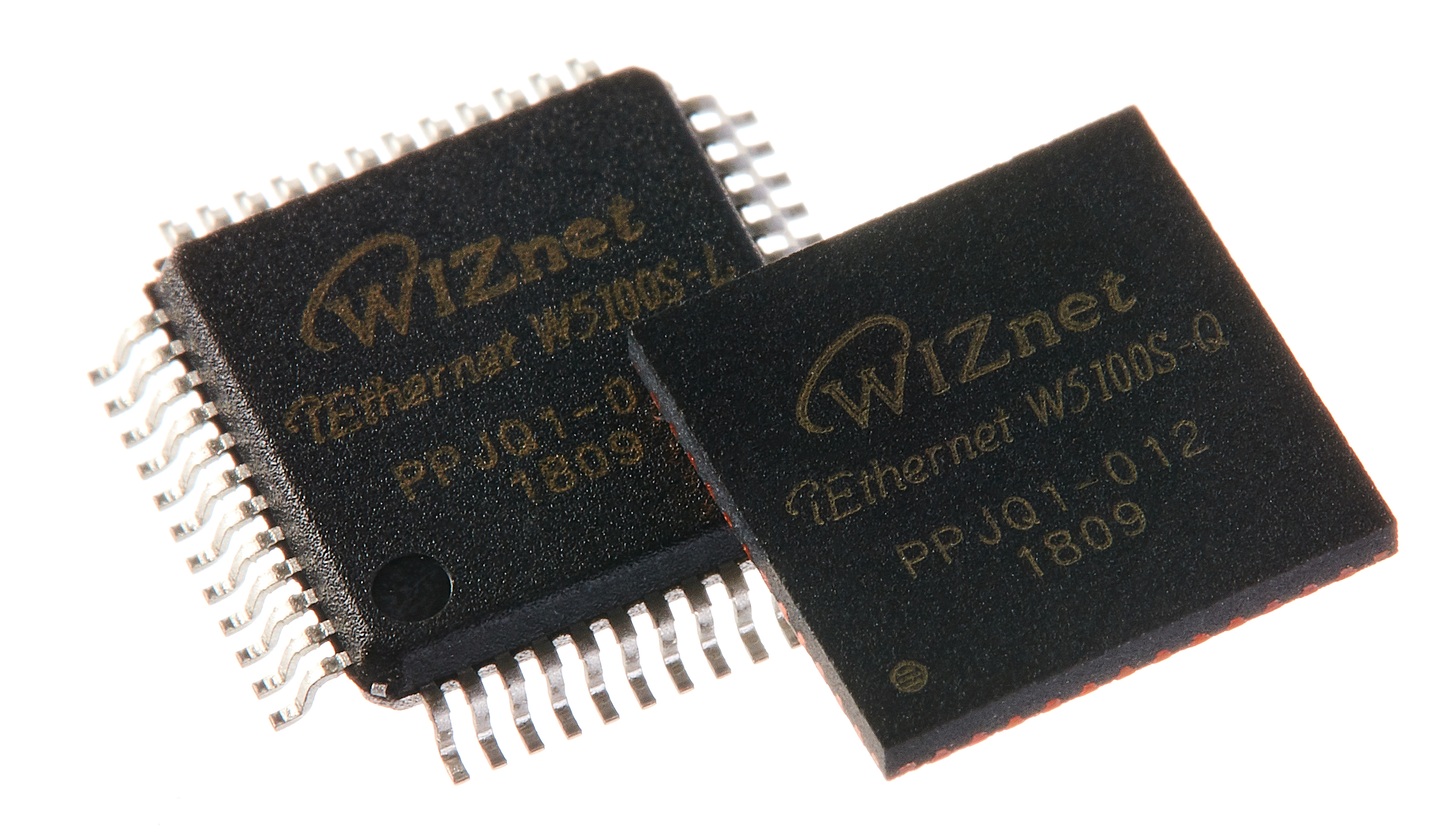
WIZnet - W5100S
x 1

Arduino - Arduino IDE
x 1
W5100S-PORT is a new product which inside the W5100S chip. The development has now been completed and there are no problems with functional verification.The current progress is small batch production. After that, samples will be sent to HQ for Ethernet compatibility test, EMC, EMI, etc.
If there are no major problems during testing, it will be released at "Embedded World Shanghai 2024 " in June and samples will begin to be provided to distributor.

In 2017, we tried to use W5500 to develop PORT products, but because W5500 uses an LQFP package, it cannot be placed on one PCB. We need to use two PCBs and connect them through connectors. These caused difficulties in production, so they were not promoted in large quantities and were only used as technical reserves.

Now, Lantronix's patent has expired, so we have restarted the design of PORT products. The first phase includes two products, the first is W7500S2E-X1, which is implemented using FPC;
the second PORT product is the W5100S-PORT introduced today, and because of the QFN package of W5100S-Q, it can With all circuits included on one PCB, production difficulty and production costs will be greatly reduced.
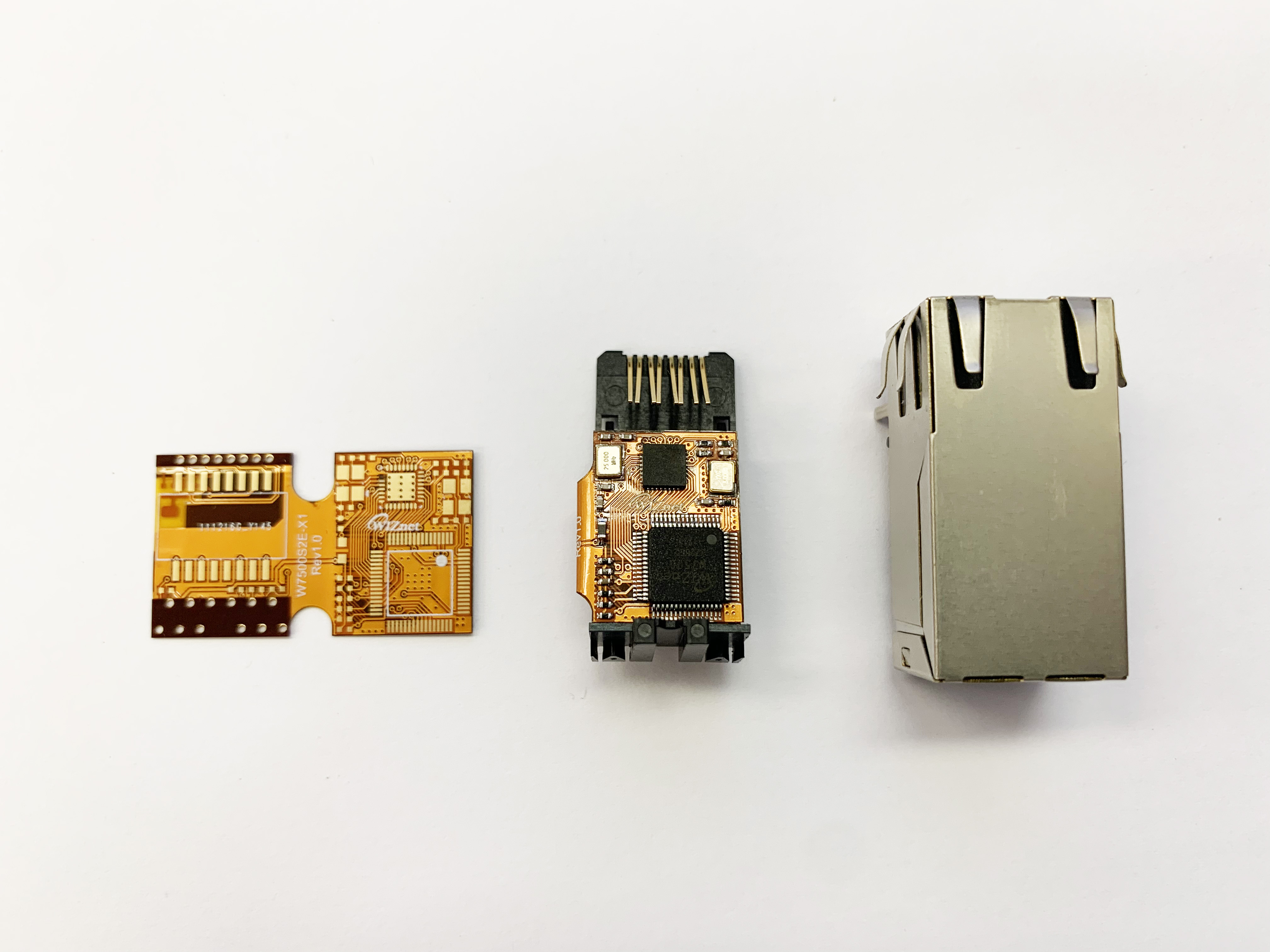
The front side of the PCB is the W5100S-Q chip and related circuits;

On the back of the PCB is the network transformer;

The PCB needs to be soldered to the base;

This is all the devices and materials needed to produce this:
RJ45 metal Shell;
op case inside the RJ45;
RJ45 internal base case;
Green LED;
Yellow LED;

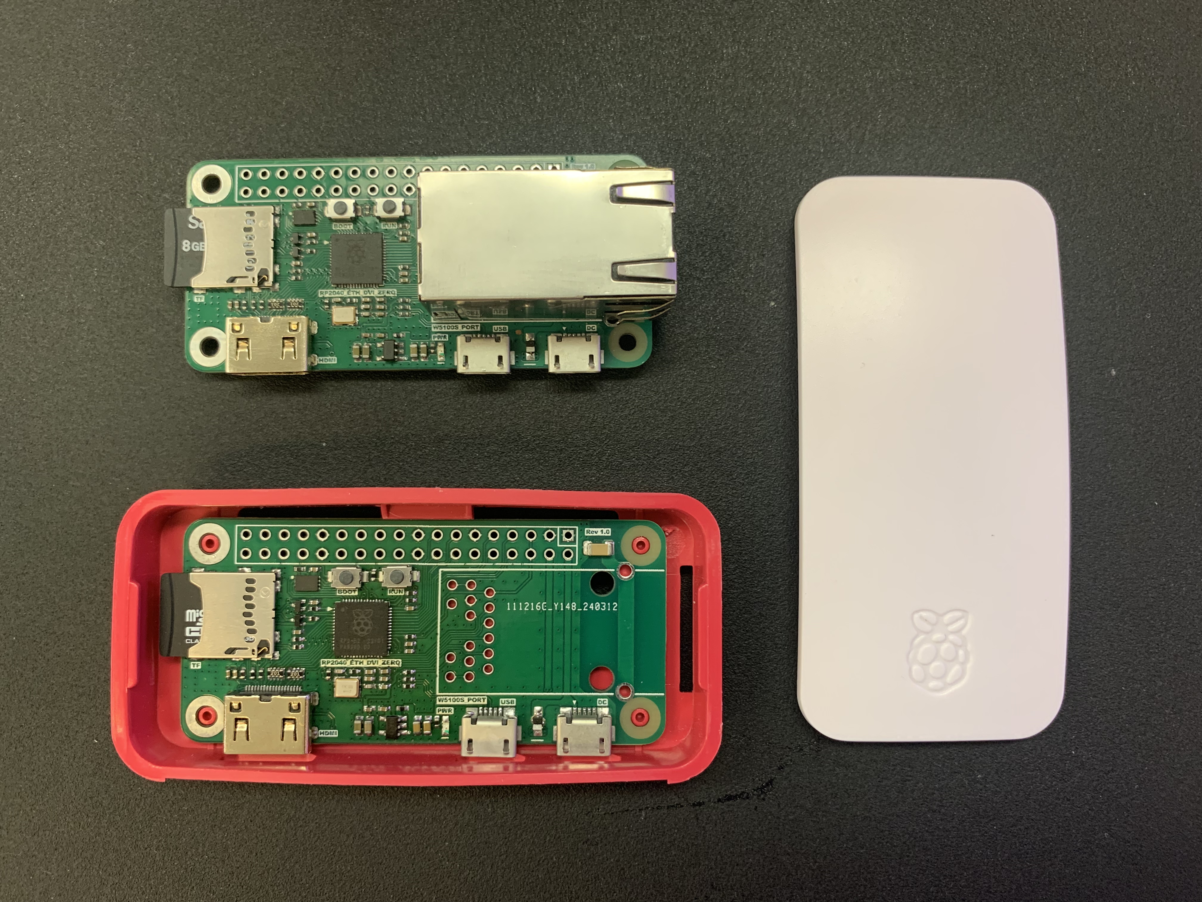
Regarding the W5100S-PORT development board, you can directly use the "IO module carrier board", such as the first board in the picture below; you can also use "RP2040-ETH-DVI-ZERO", the second board in the picture below.

“IO module carrier board” is developed based on STM32. It can test IO modules at the same time, such as WIZ850IO, WIZ810SIO, and W5100S-PORT. There are no problems with program compatibility.


“RP2040-ETH-DVI-ZERO” is based on Raspberry Pi RP2040 and has HDMI, TF card and other interfaces for convenient testing.
For functional testing, I conducted it through RP2040-ETH-DVI-ZERO, and continuously uploaded the temperature sensor data inside RP2040 to Adafruit IO. During a total of 2 weeks of testing, no functional problems were found. All data is successfully uploaded to Adafruit IO.

void setup() {
  Serial.begin(115200);

  Ethernet.init(17);
  Ethernet.begin(mac);
  // connect to io.adafruit.com
  adafruit_io.connect();

  temp_feed->onMessage(one);
  // wait for a connection
  while(adafruit_io.status() < AIO_CONNECTED) {
    Serial.print(".");
    delay(500);
  }
  // we are connected
  Serial.println();
  Serial.println(adafruit_io.statusText());
  temp_feed->get();
}

void loop() {
  adafruit_io.run();
  temp_feed->save(analogReadTemp());

  // Adafruit IO is rate limited for publishing, so a delay is required in
  // between feed->save events. In this example, we will wait three seconds
  // (1000 milliseconds == 1 second) during each loop.
  delay(5000);
}

// this function is called whenever a 'counter-1' message
// is received from Adafruit IO. it was attached to
// the counter-1 feed in the setup() function above.
void one(AdafruitIO_Data *data) {
  Serial.print("received <- ");
  // since we are using the same function to handle
  // messages for two feeds, we can use feedName() in
  // order to find out which feed the message came from.
  Serial.print(data->feedName());
  Serial.print(" ");
  // print out the received count or counter-two value
  Serial.println(data->value());
}
"A_2_temp" in the picture below is the temperature data uploaded by RP2040-ETH-DVI-ZERO.


Done.