
MiniCopter - A Programmable Nano Drone Platform
A compact and single board quadcopter platform powered with WizFi360-PA module to facilitate STEM Learning.

WIZnet - WizFi360
x 1

Arduino - Arduino IDE
x 1
1) Motivation
Drone based STEM education is an upcoming field in the world due to the vast interested towards the drone technology. However, using conventional large scale drones for learning purpose comes with several disadvantages.
- Higher cost
- Crashes make expensive damages
- Requirement of large space for testing
- Need to have a strong fundamental knowledge to start programming
Crazyflie, which is a programmable nano drone platform, provides solution for several above concerns due to its low weight (27g) and size (90mm X 90mm). After working on several projects with this platform, the requirement of a much simpler platform was emerged.
Simpler hardware architecture and Arduino IDE support were identified as driving factors to help beginner level developers to start drone programming and development. So after a few months of research, a compact drone platform was built which can autonomously fly at indoor environments.
2) Intro
Most micro drone platforms which are popular among STEM communities use two separate chips to handle the control system and communication. This contradicts with our initial idea of designing a simple hardware system. A single chip approach was ideal for this case which can handle both aspects together. But with the limitations of the payload, power supply and space we only have few options to go with. Further, since drones requires several sensors to fly, the chip should provide communication interfaces such as SPI and I2C and should have enough GPIO pins to drive other peripherals such as Motors, LEDs.
ESP12E and ESP32 WiFi modules are popular options for our requirement but come with following disadvantages.
ESP12E is comparatively performs slower due to its external flash memory.
ESP32 is larger and consumes a considerable power which drains our battery a lot faster.
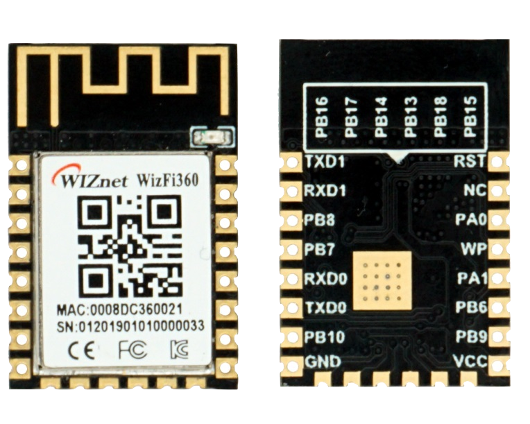
The WizFi360-PA module provides solutions for all these problems by providing enough GPIOs, communication interfaces and consumes comparatively less power.
The ideal chip for our application should be able to handle following tasks simultaneously.
- Communicate with sensors
- Run the control loop above 200Hz
- Maintain WiFi communication and receive control commands
If you know how critical these tasks and time it takes to execute these algorithms, running all these on a single chip looks impossible. So why don't we try and see how much we can achieve by the WizFi360-PA module by pushing the chip to its' boundaries.
3) Overall Hardware Design
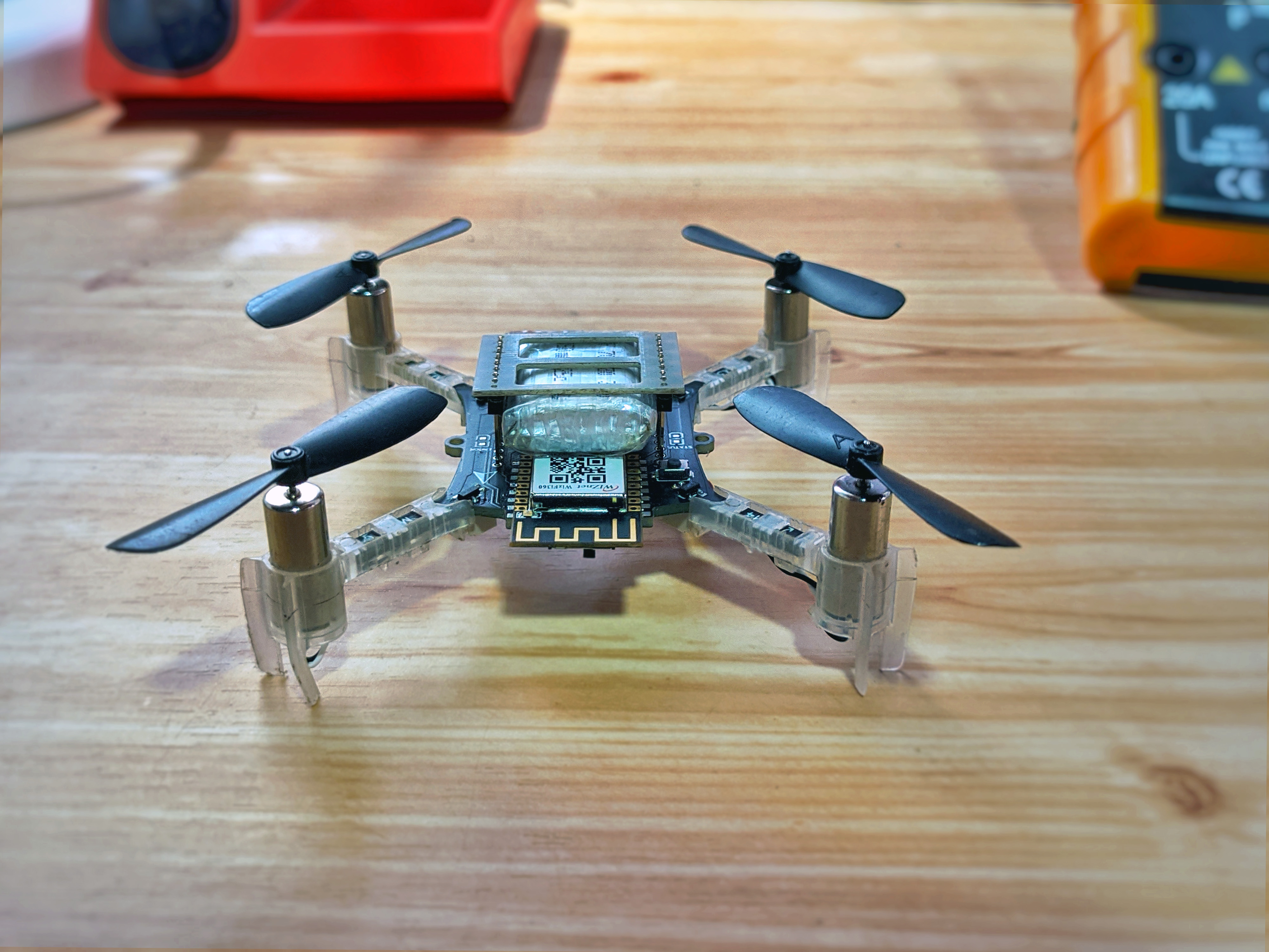
The minicopter is a minimalistic design consists of following components.
- Main Circuit Board
- Motor Mounts
- 716 Coreless Motors
- Propellers
- 500mAh 1S LiPo battery (25C)
Circuit board acts as the drone frame and drone arms. Motor mounts can be directly clipped to the PCB arms. Motor mounts, motors and propellers are sourced from Bitcraze which are being used with the Crazyflie 2.
4) Circuit Design
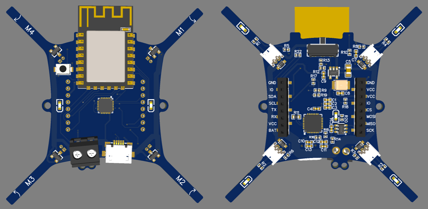
The overall design is compact and featureful to make the device easy to handle without any other electronic components and modules. The circuit area is limited to 35mm x 32mm hence when selecting components 2 facts were considered; low price and smaller size. The following section explains technical facts and the strategies used to overcome problems when using the selected components.
4.1)USB Programming
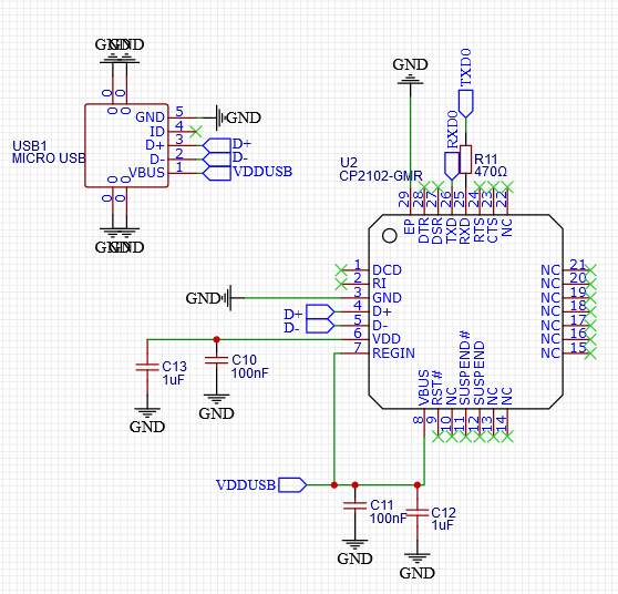
Onboard USB programming allows users to easily program the platform without any additional UART converters. Though CH340 is a cheaper option considering its' size, it is decided to use the CP2102 UART Converter IC. The IC powers up through the USB port and the internal regulator is bypassed by connecting the REGIN pin to VDDUSD.
4.2) LiPo Charger
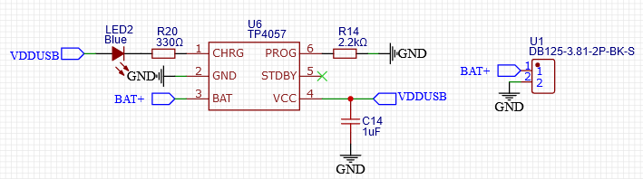
The drone runs with a single cell lithium polymer battery. A capacity in between 400-500mAh is preferred with a discharge rate of 15-25C. In order to charge the battery when the USB plugged in, a charging controller IC is mounted with an indicator LED. TP4057 is chosen due to its smaller size and popularity.
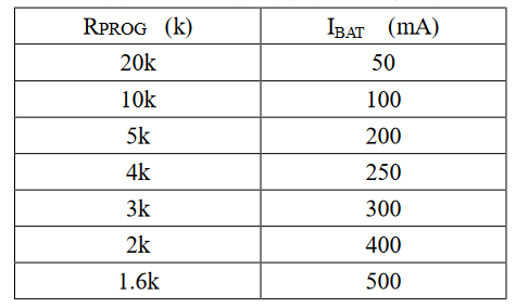
Charging current can be controlled by changing the resistor value connected to the PROG pin. It is advisable to keep the charging current below 1C to avoid reduction of battery health. Datasheet has provided necessary equations and the following table to calculate the resistance according to the charging current.
4.3) Power Regulator
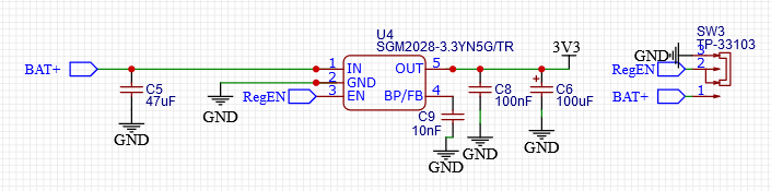
All the sensors and the WizFi360 module use 3.3V as the supply voltage. When powering up with the battery the input voltage changes in between 3.5V - 4.2V. The nominal battery voltage is 3.7V and it becomes 4.2V when fully charged. At lowest we can expect around 3.5V when it is discharged to a safe low margin.
Popular 3.3V regulators such has AMS1117 has higher dropout voltages (around 1.2V) which makes it unsuitable for our application. We want our MCU to work even when the battery is at 3.5V, hence a LDO regulator with a 0.2v dropout is preferred which can provide 500mA current. SGM2028 is selected considering all these aspects and without compromising our initial conditions.
2 larger capacitors have been added to facilitate sudden voltage spikes and a smaller capacitor is added to reduce high frequency noise. Smaller On/Off switches doesn't facilitate higher currents to pass through. An SPDT switch with a current rating of 50mA is used to drive the EN pin of the LDO to solve this problem.
4.4) Motor Driver
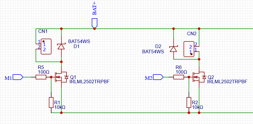
A MOSFET based motor driver is used to drive 4 coreless motors of the drone considering its simplicity. Speed of the motor can be controlled by applying a PWM signal with varying duty cycles to the Gate pin of the MOSFET. The maximum current draw of each motor stays around 1.6Amps when used with the selected propeller size. IRLML2502 which supports up to 4A is selected to avoid unnecessary heating and keep headroom for developers to upgrade the motor to a larger size.
Speed of the motor is controlled by providing a PWM signal to the Gate pin with varying duty cycle. Since WizFi360 provides 5 PWM channels, 4 motors could be easily driven with separate speeds.
Schottky diodes are applied in between motor terminals to protect the circuit from reverse voltages generated by motors. 1250WR-2P connectors are used instead of soldering pads to make it easy to change motors when it is needed.
4.5) Inertial Measurement Unit (IMU)
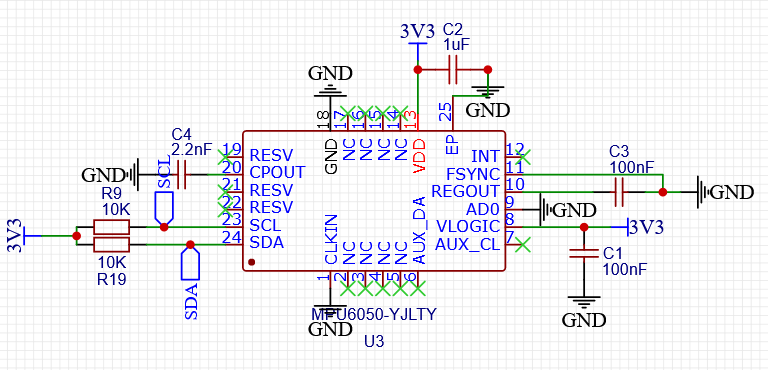
IMU is the most critical sensor of a drone which helps to detect the orientation and maintain the stability. For a drone, at least a 6DoF IMU is required which consists of an accelerometer and a gyroscope. There are 9DoF IMUs in the market which additionally comes with an inbuilt magnetometer. But a magnetometer is not essential to fly a drone unless advanced features such as headless mode are not intended to use.
There are several drone friendly low cost IMUs in the market and ICM-20648 and BMI088 are two of popular modern IMUs. But for this development, MPU6050 is selected considering its popularity and availability though it is an outdated model. However, modern IMUs provide much more stable readings and accurate than MPU6050 consequently resulting a smoother and a stable flight.
4.6) Misc.
2 pin headers were used to provide access to GPIO pins of the MCU. This can be used to connect external sensors via I2C bus. A reset button has been placed on the top surface to control the reset pin.
One of the limitations of the WizFi360 PA module is it uses same pins for both PWM and SPI. Further investigations are required to check the possibility of using other GPIO pins as PWM outs and give access to the SPI port. However, SPI pins are routed to the connector header to use the platform as a development board when not using motors. The SPI Init pin is connected to one of the header pins so that it can be connected easily with GND to activate the SPI mode.
Routing is done only using 2 layers. To avoid unnecessary heating when drawing 1.6Amps by each motor, the width of motor power rails are set to 60mils. Further, this allows users to improve the motor size.
5) Programming
The intention of this section is to provide a guide on start programming the drone, not to provide the fully functioning code as it is considered as proprietary at this stage and contains around 3000 lines. Those who are interested in further developments could start implementing their own algorithms and test using the minicopter platform.
5.1) Setting up the environment
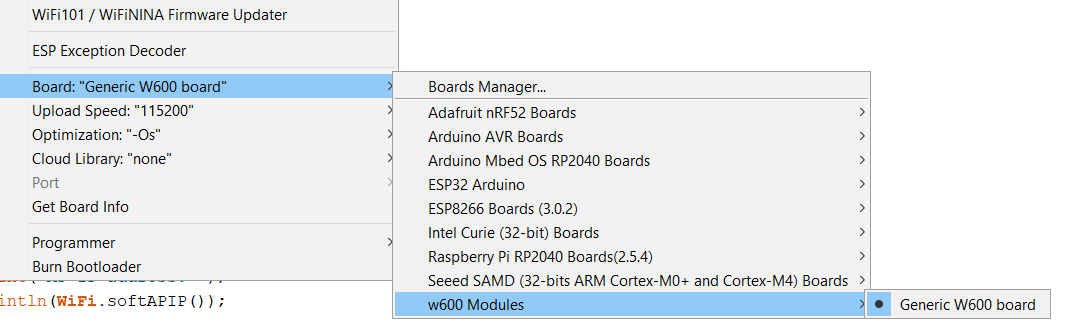
The WizFi360 module contains the "Winner W600" chip. The following steps explain how to install the w600 plugin to the Arduino IDE.
- Download the W600 Arduino Plugin.
- Extract all the compressed files until you get "w600-arduino-InnerIDE-0.2.6" folder.
- Copy the "w600-arduino-InnerIDE-0.2.6/hardware" folder to "../Arduino" directory. In Windows default Arduino installation folder is located at "C:\Program Files (x86)\Arduino"
- Restart the Arduino IDE and you should be able to find "Generic W600 board" in the board menu.
Try compiling the bare minimum code and see whether it compiles successfully. In my case, a directory error kept occurring as follows though those folders actually exists.

To fix this error I used the Arduino Portable Version as explained below.
- Download Arduino IDE Portable.
- Extract the compressed file to a desired directory and follow 3rd step above and copy the files to the hardware folder of the Arduino Portable Directory.
- Open Arduino.exe inside the Arduino Portable Folder and do the compilation again.
5.2) Wireless Communication
As explained earlier we have taken a challenge to perform both communication and control system tasks inside a single MCU while keeping a higher loop rate. In our experiments we run the control loop at 400Hz and communications at 50Hz. Though TCP IP protocol is a reliable method, due to its multiple handshake rounds it adds a considerable delay to the control loop. Therefore UDP is used to communicate between the PC and MCU and found it reliable through out all the tests we performed.
The linked git repo contains a sample code to initiate UDP communication in between the MCU and a python script.
In addition to the W600WiFi library we need to import WiFIUdp library to initiate the communication with following lines.
WiFi.softAP(APPSSID, PASSWORD);
UDP.begin(UDP_PORT);
When a UDP packet is received the following lines will catch the packet. The packet contains a JSON string. You may use a preferred JSON decoder to decode the packet.
int packetSize = UDP.parsePacket();
if (packetSize){
   int len = UDP.read(incomingPacket, 255); // receive incoming UDP packets
   //=========================================
   //decode the incoming packet here
   //=========================================
}
The basic structure of the python script is as follows. You need to define the same UDP_PORT number in both Arduino and Python codes. Once the MCU start running it will print the IP address on the Serial Monitor. Modify the python code with the same IP.
Use the json plugin to encode the message as follows and send the packet through the socket.
5.3) IMU and I2C Lines
The bottleneck to achieve a higher control loop rate comes when communicating with sensors which provide critical measurements. If the communication time is high, then we need to find a strategy to retrieve sensor measurements within a shorter time. If we need to run the loop at 400Hz, we have 2500uS to complete a cycle.
In a basic drone control system, the bottleneck occurs with IMU communication via I2C lines. Some advanced drones are using SPI to avoid this. In our case we use the i2c port hence time factor is really critical. There are several 3rd party libraries for mpu6050 but most of them have unnecessary processes inside which consumes more time to execute. To overcome that, an efficient customized IMU library is added to the repo.
Mainly we increase the speed to 400kHz and run only critical functions and call only essential registries to retrieve measurements. The following line depicts important points of the library. The last command has an argument where you need to pass either true or false. This represents whether you want to convert IMU measurements to standard units(true) or get raw value(false).
Wire.setClock(400000L);            //Set clock frequency to 400kHz

mpu6050_init();							//Initialize IMU

read_imu(true);							   //Update IMU variables
As observed, this library updates all imu variables within 500uS which leaves us 2000uS to perform other calculations.
5.4) PID
PID controllers are one of the key components of the drone stabilization system. In the demo video, the drone simultaneously run 11 PID controllers for following tasks.
- Roll and Pitch Control - 4 PIDs
- Yaw Rate Control - 1 PID
- Altitude Control - 2 PIDs
- Position Controller - 4 PIDs
The used PID library is added in the repo which can be easily use by creating multiple instances. Following are the key functions of the library.
The init() function initialize the PID given the P, I and D gains, limit for the integral term (I), limit to the overall output value and sample time in seconds.
init(const float p, const float i, const float d, const float i_limit, const float out_limit, const float sampleTime);The update() function calculates the PID output given the current and desired states.
update(float input, float set_point);If you need to change gains while flying the following command can be used.
change_gains(float p, float i, float d);Finally, reset() command helps to reset internal values of the PID without clearing gains. This helps to achieve a smoother take off by resetting all the PIDs just before taking off. Otherwise all PIDs might have converged to higher values and result a bumpy start.
5.5) Motor Speed Calculation
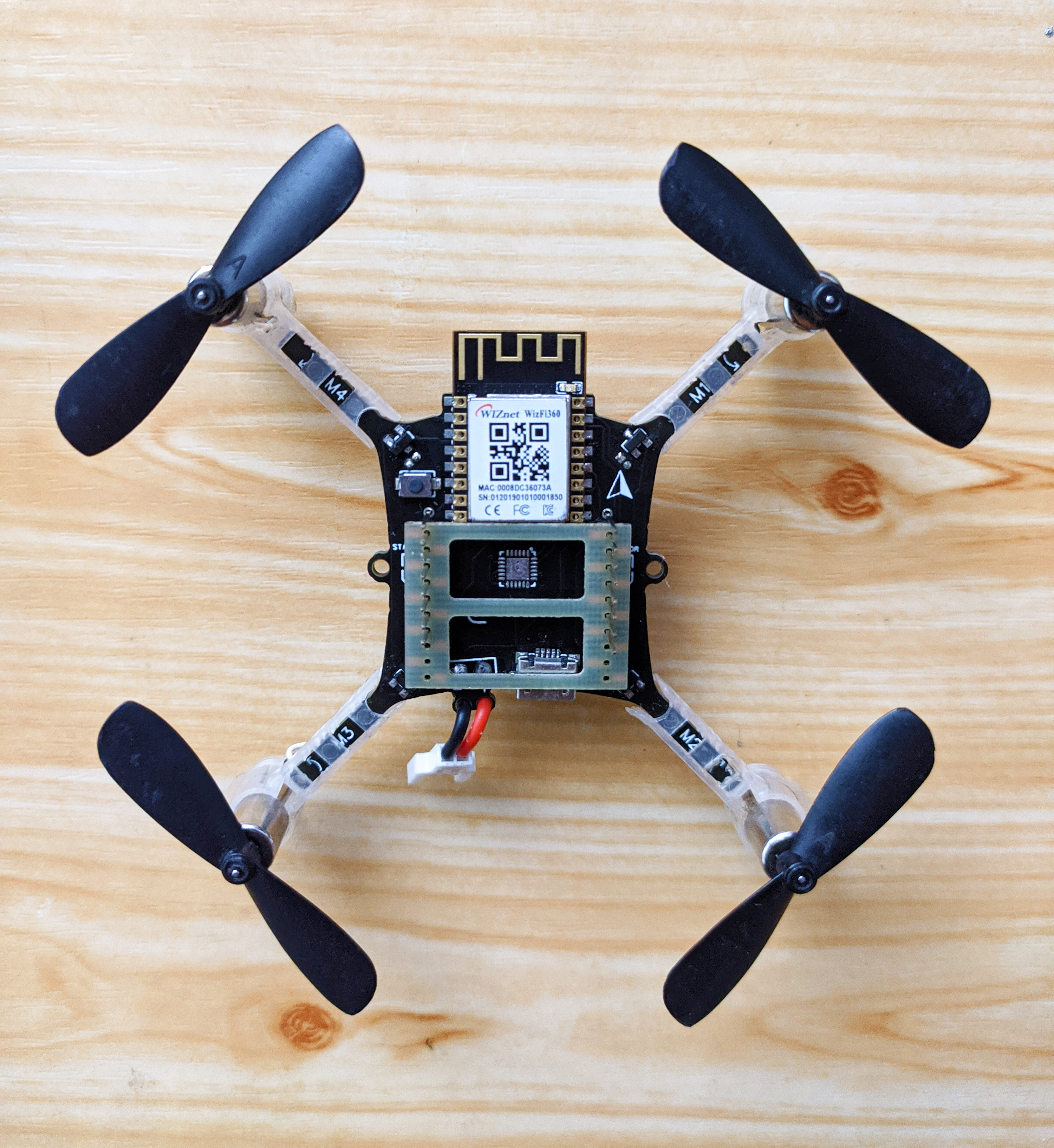
All possible movements of a quadcopter are performed by controlling the speed of 4 motors. The speed of the motor is represented by the PWM value in the control system. In the stabilization mode we need a method to calculate PWM value for each motor after obtaining outputs from Roll, Pitch and Yaw correction PIDs.
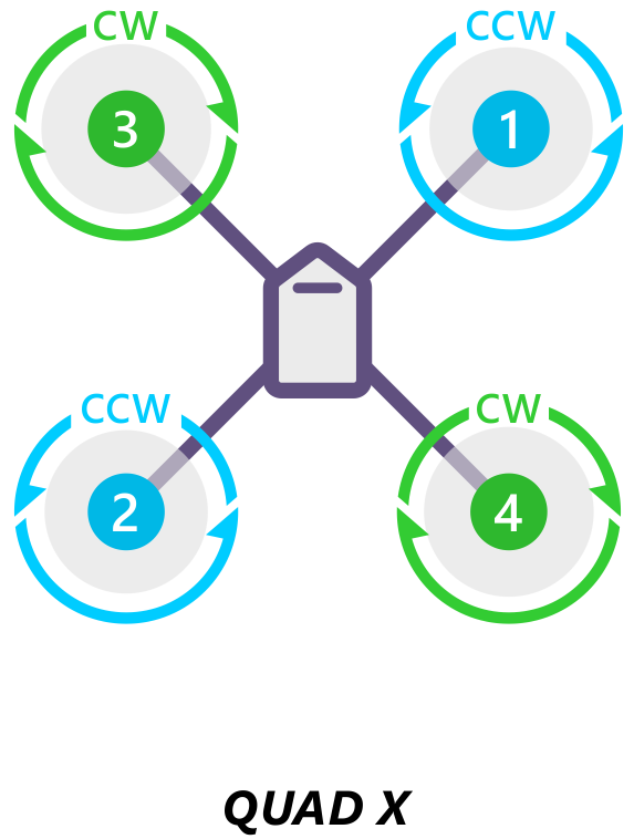
The above motor numbering and propeller rotation convention is followed to implement the following power distribution function.
    m1 = throttle  + pitch_correction  -  roll_correction  +  yaw_correction;
    m2 = throttle  -  pitch_correction  -  roll_correction   -  yaw_correction;
    m3 = throttle  -  pitch_correction +  roll_correction  +  yaw_correction;
    m4 = throttle  + pitch_correction +  roll_correction  -   yaw_correction;
Make sure to map each speed to the PWM range.
5.6) Overall Algorithm Structure
In the world of drones we define 3 main controlling modes.
- Stabilize - Altitude, Roll, Pitch and Yaw are manually controlled.
- Altitude Hold - Drone automatically holds the given altitude.
- Position Hold - Holds the given position and altitude.
In the demo video we are flying in the position hold mode and the algorithm is much more complex. In the initial steps we need to implement the stabilize system and make sure that it works well before implementing other two features. The following structure will guide you to implement the main control loop to implement a stabilization system.
int loop_count = 0;

void loop(){

		loop_counter++;

		if (loop_counter == 8){		//run rc link at 50Hz
			read_udp_packet();
			loop_counter = 0;
		}

		read_imu();							// get IMU measurements
		calculate_pid();						// calculate roll, pitch and yaw correction values
		power_distribution();			// calculate pwm for each motor using pid outputs
		motor_write();						// write pwm values for motors
		loop_rate_controller();			// maintain the loop rate at 400Hz
}
6) Conclusion
It is needed to have a deeper understanding of mathematical modeling and coding to achieve capabilities as shown in the demo video. In our case, two additional sensors are connected to support the constant altitude and position maintaining algorithm; a ToF sensor and an Optical flow sensor.
In conclusion, the hardware platform has provided pins to connect additional sensors as you desire and facilitated to implement your own algorithm. Being smaller in size and light weight allows to crash many times without damaging components or harm your self.
So its your time to build, code and fly!!! For further information please visit https://srqrobotics.com