
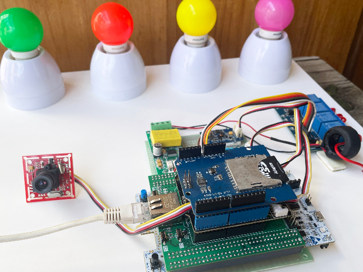
W5300 Based Highly Secure & Reliable Smart Home Hub
W5300 Ethernet-based hub collects data from connected sensors and publishes to Cloud. Simultaneously receives commands and sends to devices.
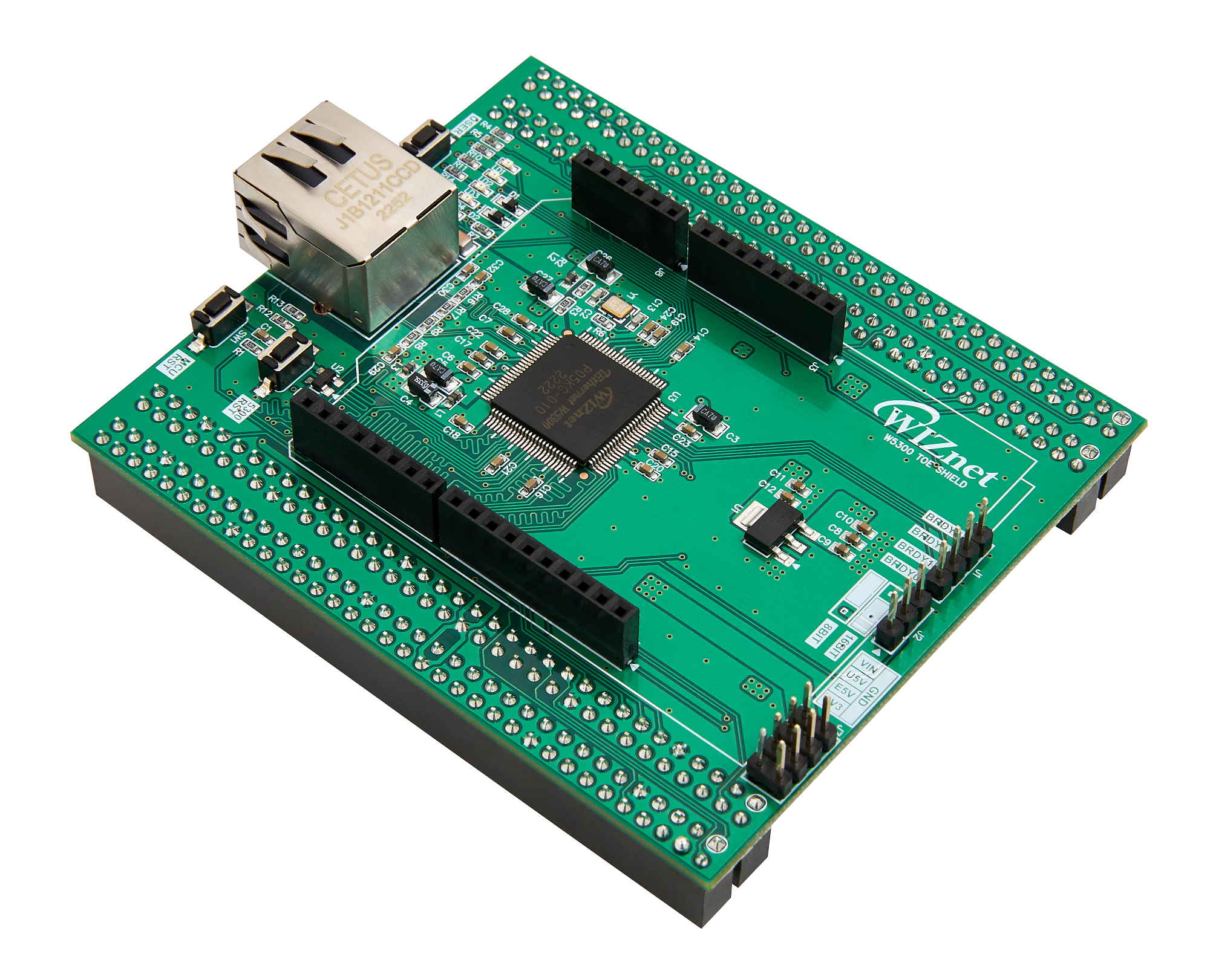
WIZnet - W5300-TOE-Shield
x 1

seeed - Grove - Air quality sensor v1.3
x 1

Seeed - Grove Beginner Kit for Arduino-Old Version
x 1

seeed - Grove - Serial Camera Kit
x 1

seeed - Grove - 4-Channel SPDT Relay
x 1
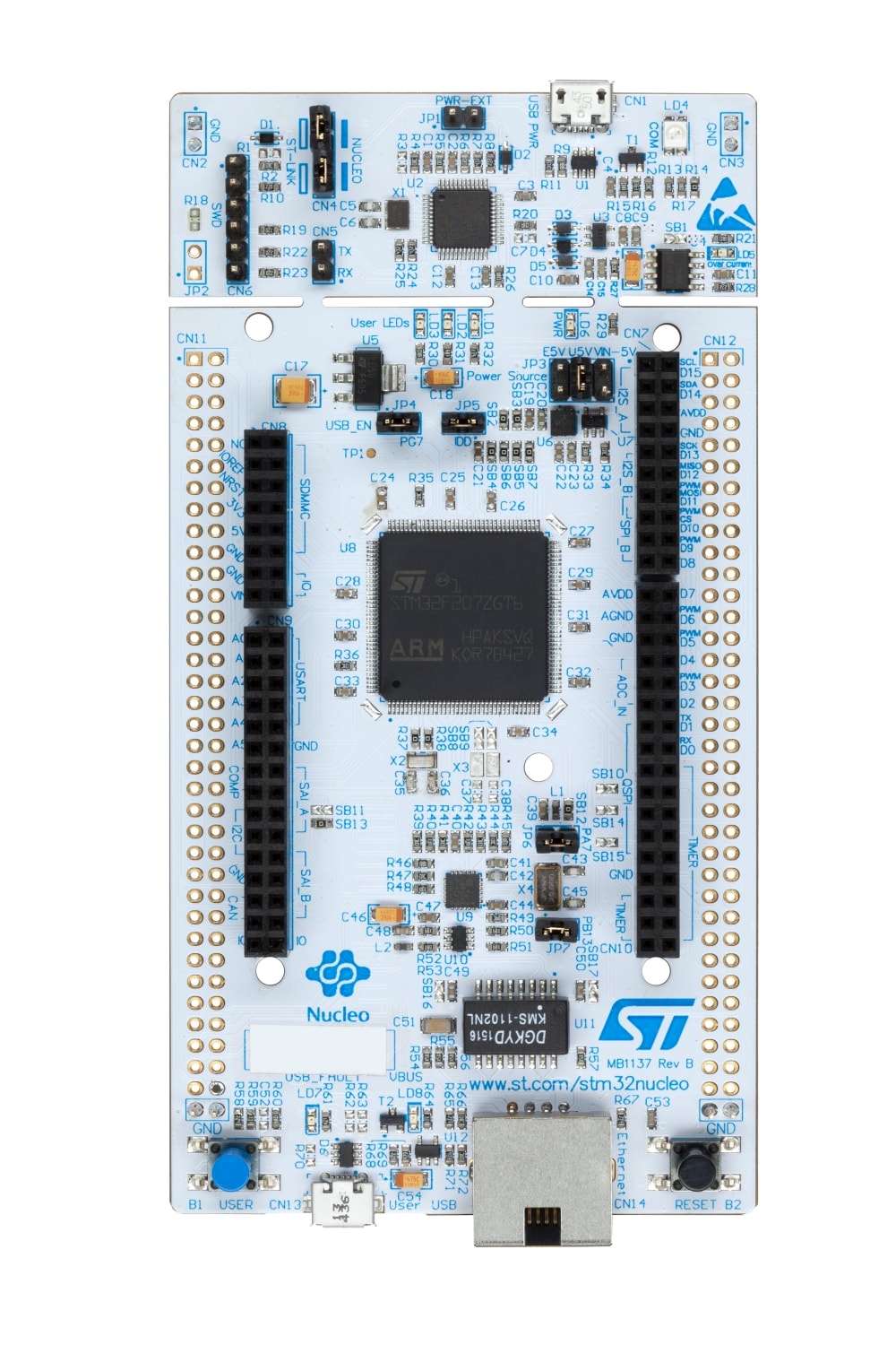
ST - NUCLEO-F429ZI
x 1
Or ST - NUCLEO-F722ZE
Eclipse - Paho MQTT
x 1
APP Inventor - MIT App inventor
x 1

node-red - Node-RED
x 1
WIZnet - WIZnet io Library
x 1
Introduction
A smart home is a hardware system that enables connection and communication between other devices on the home automation network. These devices include thermostats, light bulbs, wall outlets and switches, door locks, energy monitors, window coverings, appliances, motion sensors, etc. While these devices provide convenient functions to users, such convenience may come at a greater cost, such as the leakage of the user’s private information. With an intelligent hub, all of these smart devices can be controlled using a single app.
The smart home hub is a hardware device that acts as the central point of the smart home system and can sense, process data, and communicate wirelessly.
According to a recent study, on average, 10 smart-home devices were deployed in U.S. houses in 2020. By 2025, nearly 75 billion devices will be installed. The proliferation of smart-home devices is mainly due to the convenience that users can easily access the devices to monitor and control their homes via smartphones and Internet access. However, this convenience comes at a cost. Specifically, the wide use of smart-home devices risks the breach of user privacy. An adversary with information about the usages/states of smart-home devices could obtain sensitive and private information about the users and their activities. i.e., what sensors are triggered or when the sensors are used. These device states often contain the users’ activities in their homes which, in turn, the adversary can use to initiate further offenses, e.g., burglary, with the information. In fact, cybercriminals are increasingly targeting smart-home devices.
This project demonstrates the details of a smart home hub for user privacy and accessibility, enabling an adversary to infer smart home events and user activities by only sniffing encrypted network traffic to/from a target home. More importantly, my insight to design is that users’ activity can routinely trigger smart devices so that an adversary can identify and learn distinct patterns in the network traffic despite being encrypted. The adversary can infer users’ activities in the smart home by analyzing the event-triggered times and distinct patterns in the network traces.
Features of the System
This smart home hub enables you to monitor and control your smart home devices by maintaining security. The following are some important functionality of the project:
- Can monitor the voltage, current, power, energy, frequency, and power factor and alert the user in case of any abnormality.
- Can monitor the temperature, humidity, and air quality of the inside of the house.
- Users can monitor the inside of the house remotely by the connected camera through a smartphone application or web browser.
- Users can monitor the status of any appliance in the house.
- Users can control any connected appliance remotely from the smartphone app or from the web browser.
Watch the Project Demo
How I made it?
The project is open source and the following step-by-step instructions will give you all the required information to make it. Before getting started make sure that you have all the required components in your bucket.
To make the project the following components will be required:
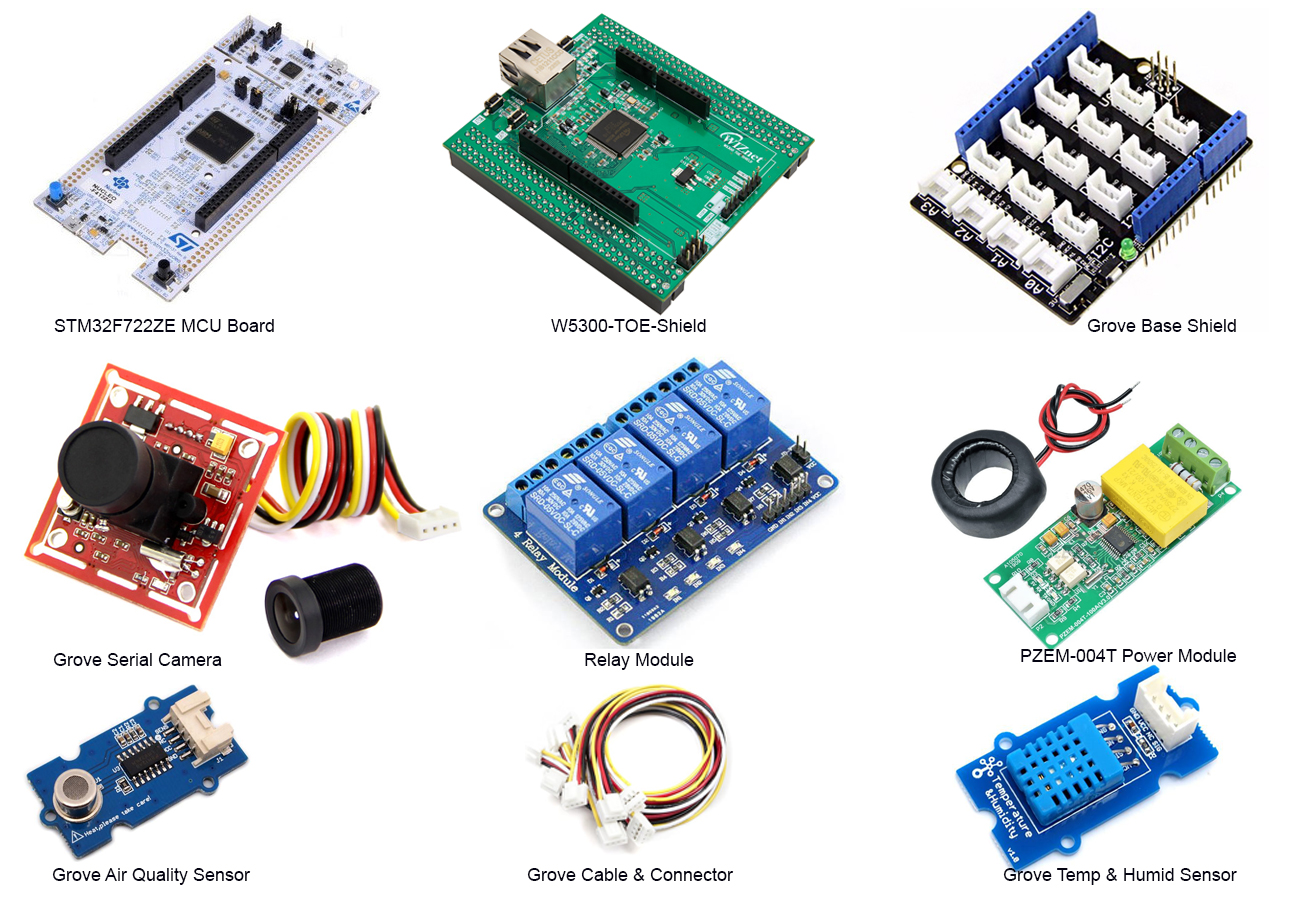
You also required some basic tools like soldering iron, wire cutter, male and female pin headers, jumper wires, and PCB perf board.
Hardware Making
Step 1: Soldering Pin Headers to STM32 Nucleo Board
Your STM32F722ZE Nucleo board may not come with the pre-soldered male pin headers. In that case, you need to solder double line male pin header to both sides of the Nucleo board. These pin headers will be used to connect the W5300-TOE-SHIELD with the Nucleo Board. I soldered the pin headers on both sides as shown in the following image.
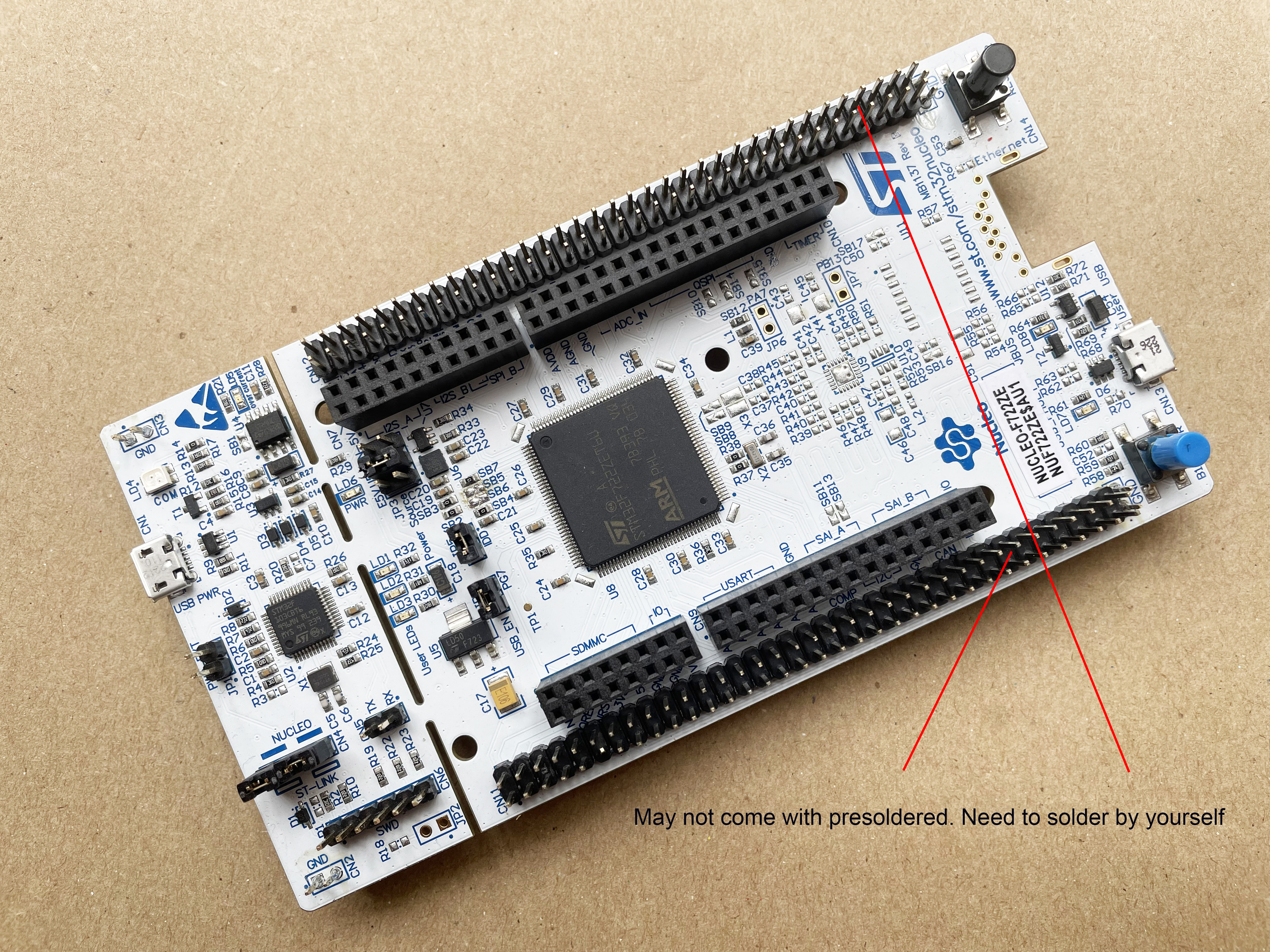
If you don't have a NUCLEO-F722ZE board the NUCLEO-F207ZG, NUCLEO-F429ZI, NUCLEO-F439ZI, NUCLEO-F756ZG, and NUCLEO-F767ZI should also work but I did not test it in those board.
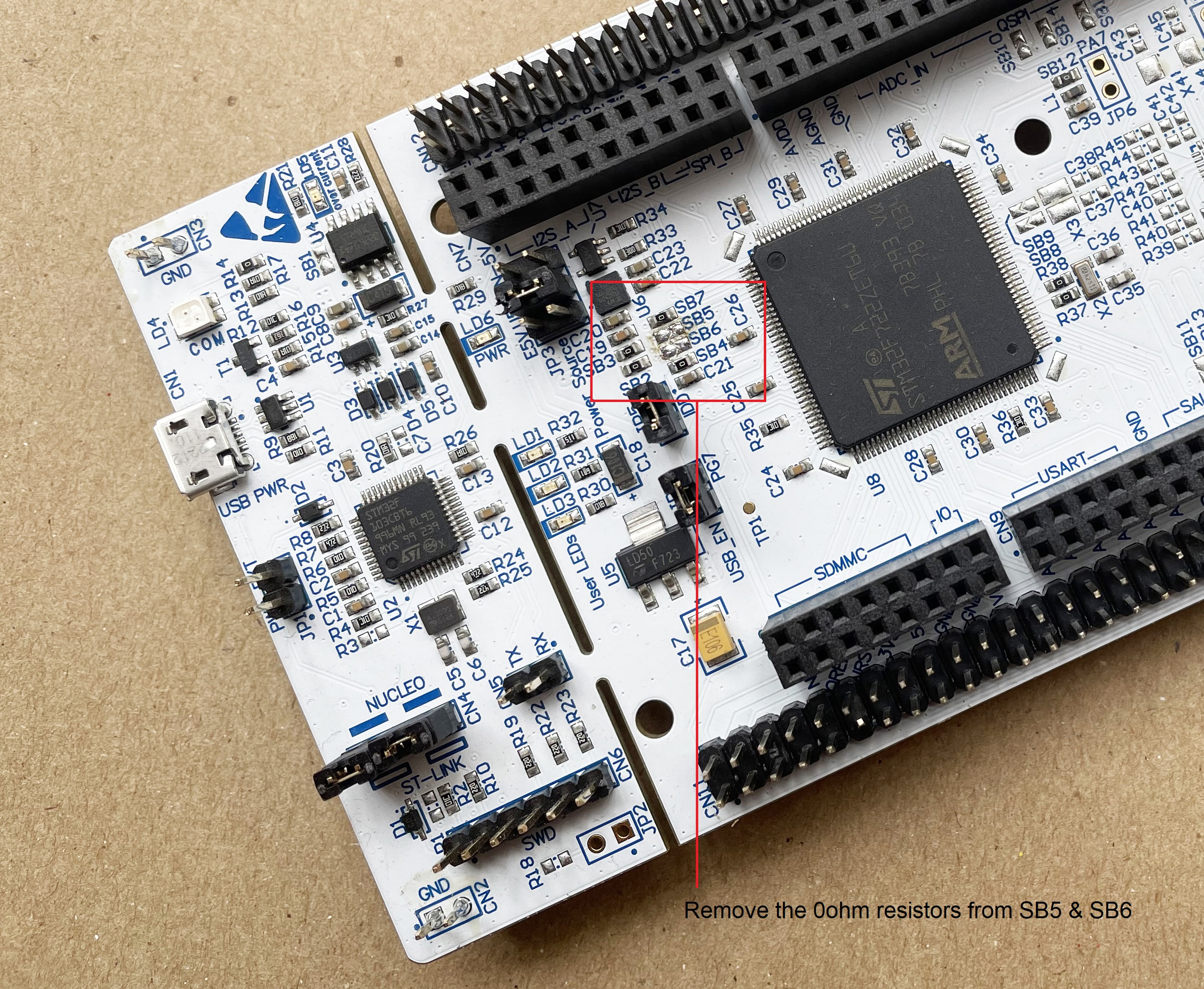
Step 2: Removing SB5 and SB6 resistors from the top of the STM32 Nucleo-144 board
The default ST-LINK pin is PD8 and PD9. But these pins will be used for the FMC(Flexible Memory controller) data pin to control the W5300 built in the W5300 TOE Shield and the ST-LINK pin of the STM32 Nucleo-144 board.
Therefore, in order to use the ST-LINK of the STM32 Nucleo-144 board, we will use PC10 and PC11 instead of PD8 and PD9. So, first we need to open PD8 and PD9 of the STM32F722ZE microcontroller for W5300 TOE Shield by removing the SB5 and SB6 resistors as shown in the following image.
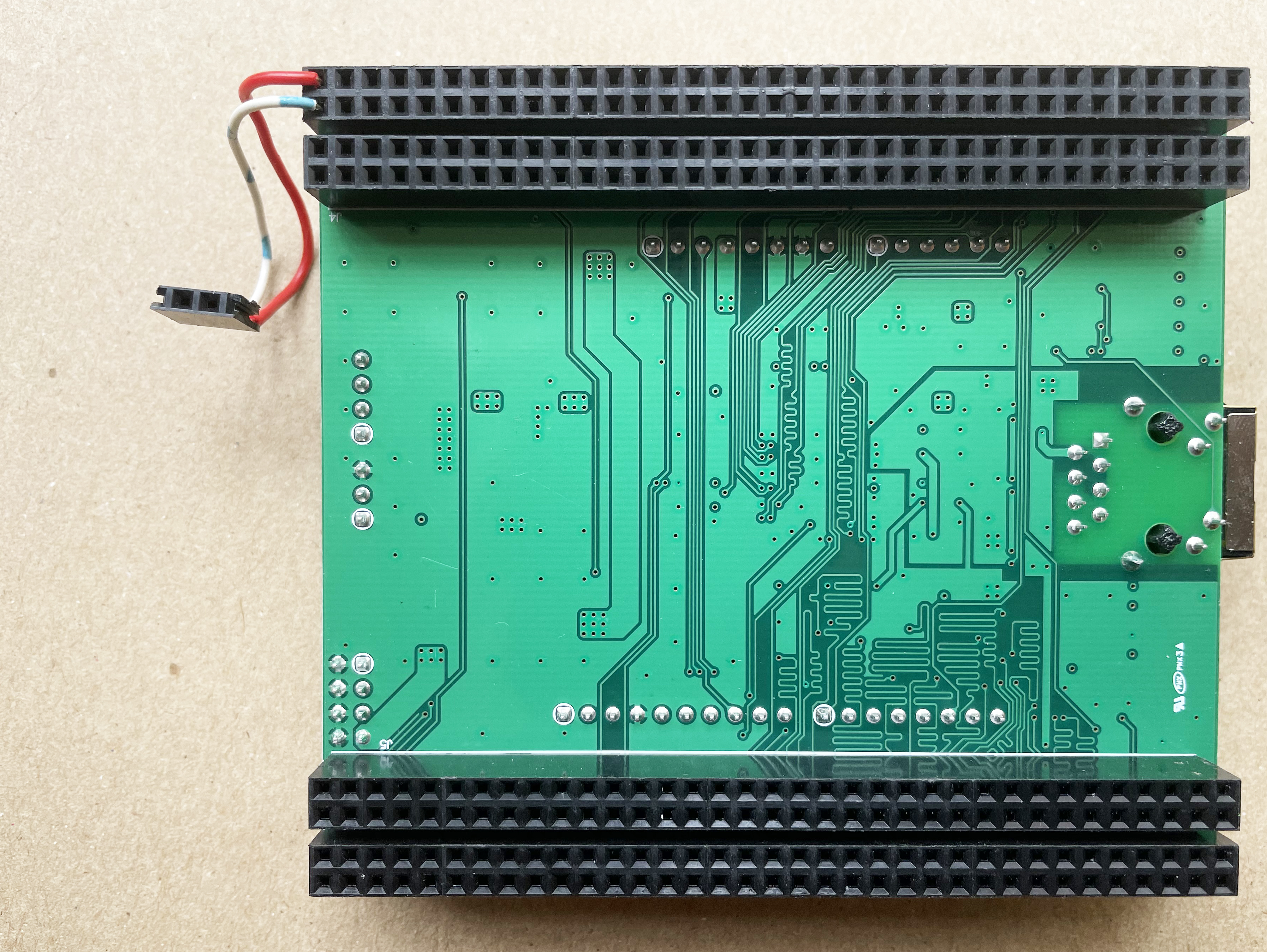
Step 3: Connecting TX, RX of Nucleo Board to W5300 TOE Shield
Now we need to connect PC10, and PC11 of the W5300 TOE Shield and CN5 TX, RX of the top of the STM32 Nucleo-144 board with jumper cables.
- W5300 TOE Shield : PC10 - STM32 Nucleo-144 board : RX
- W5300 TOE Shield : PC11 - STM32 Nucleo-144 board : TX
The following image shows my jumper connection with the female pin header.
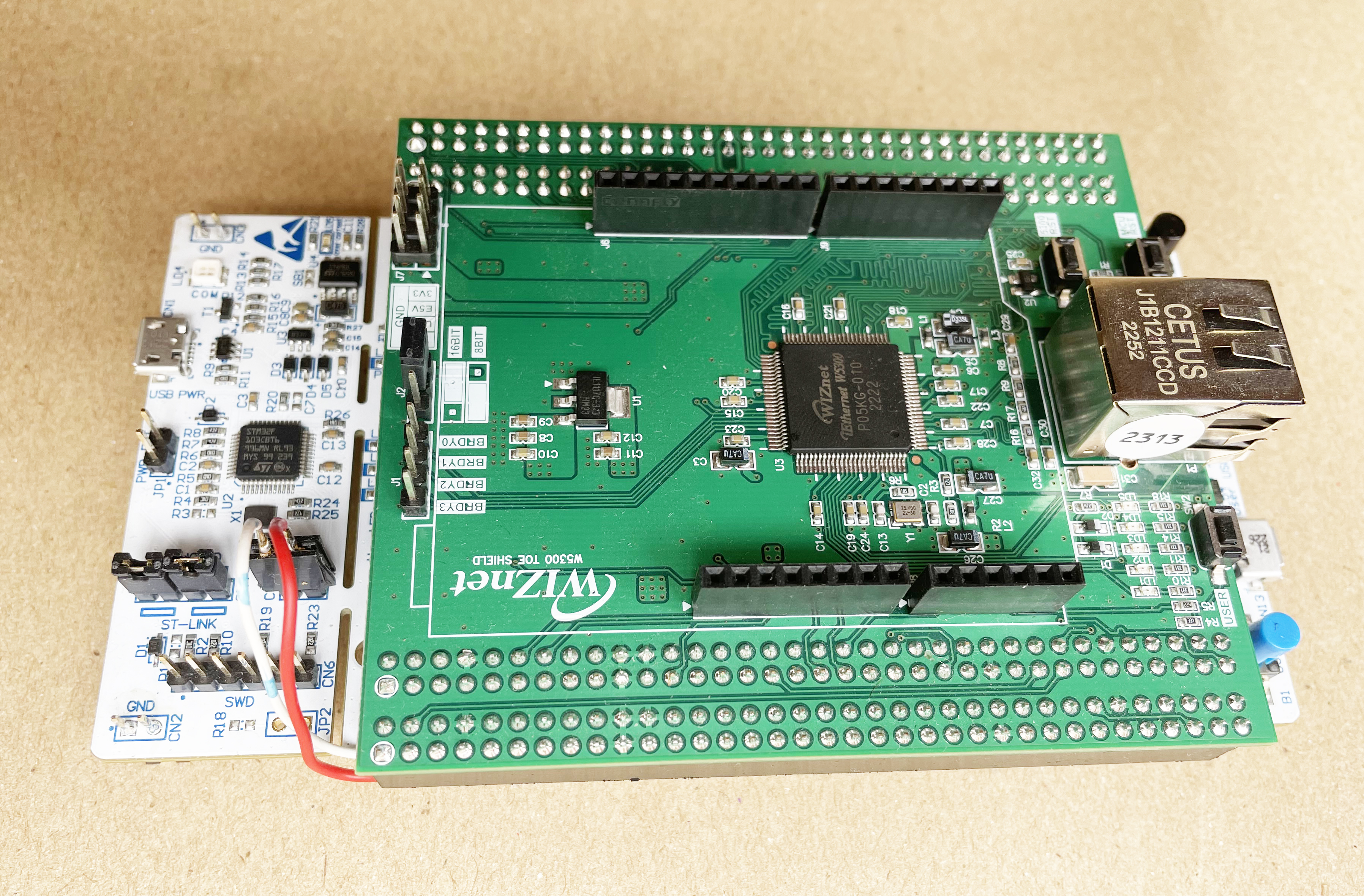
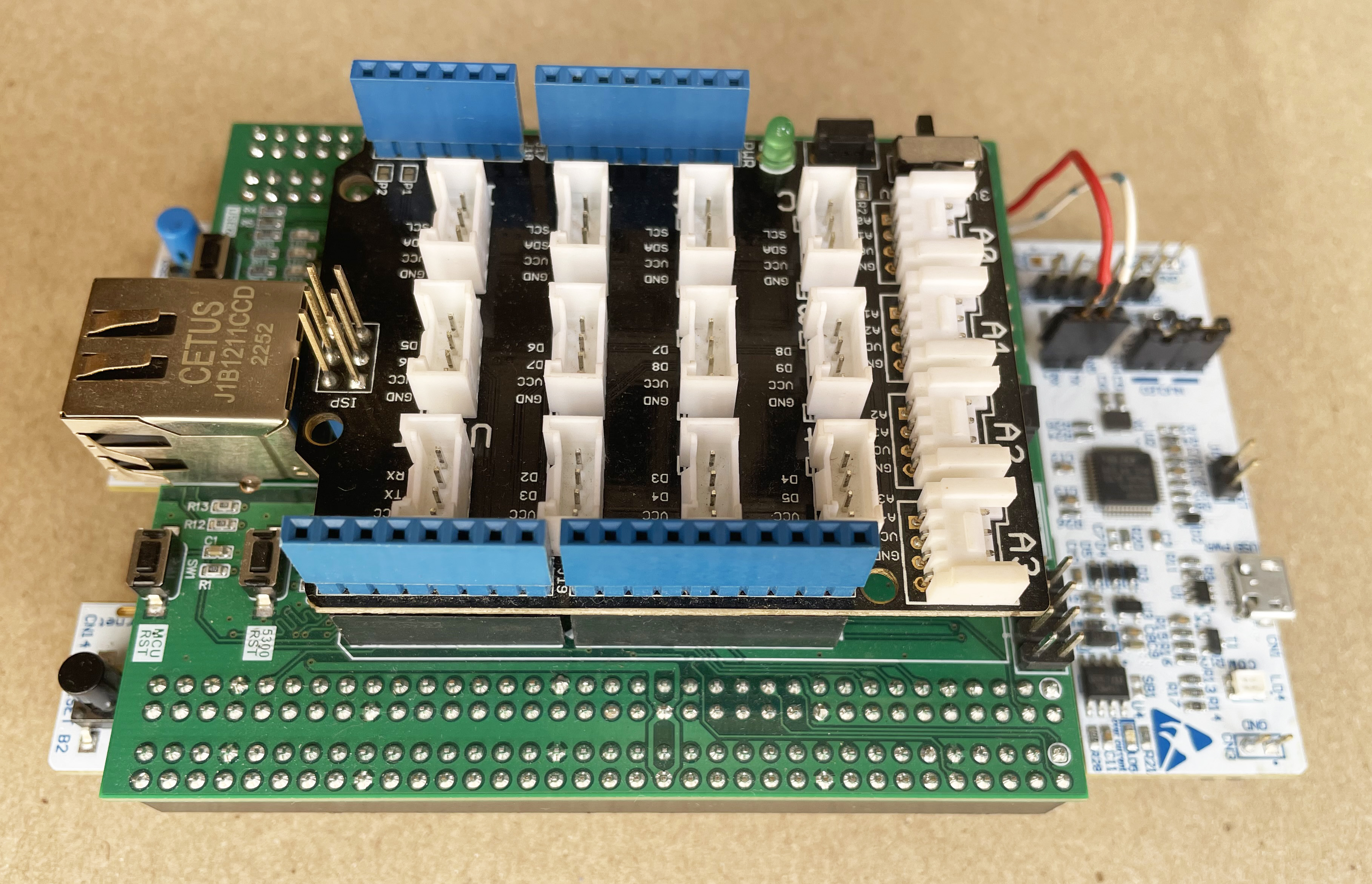
Step 4: Attaching W5300 TOE Shield with STM32 Nucleo Board
The following image shows the attached Nucleo board and TOE shield.
Step 5: Attaching Grove Base Shield
For connecting Grove sensors with the Nucleo board I am using Grove Arduino Base Shield. The base shield has several Grove connectors through which we can easily plug and play any Grove sensors or actuators. Fortunately, the W5300 TOE SHIELD has an Arduino compatible header to which we can attach any Arduino shield.
The following photo shows how I attached the Grove Base Shield with W5300 TOE SHIELD.
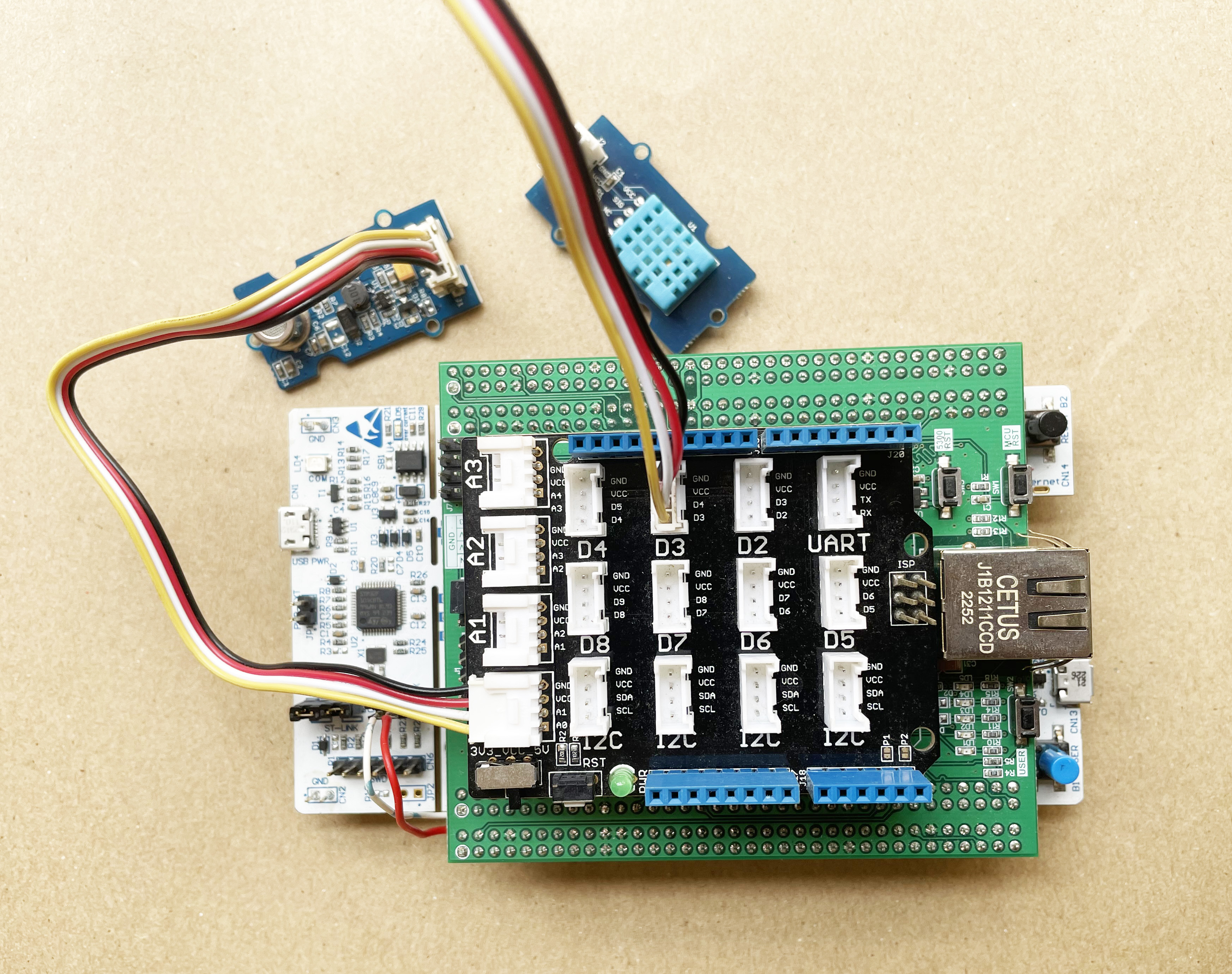
Step 6: Connecting Grove Sensors
Connecting Grove sensors with the base shield is very easy. I connected the DHT-11 temperature and humidity sensor to the D3 port and the Air Quality sensor to the A0 port of the base shield. You can use different ports but you need the adjust the program accordingly.
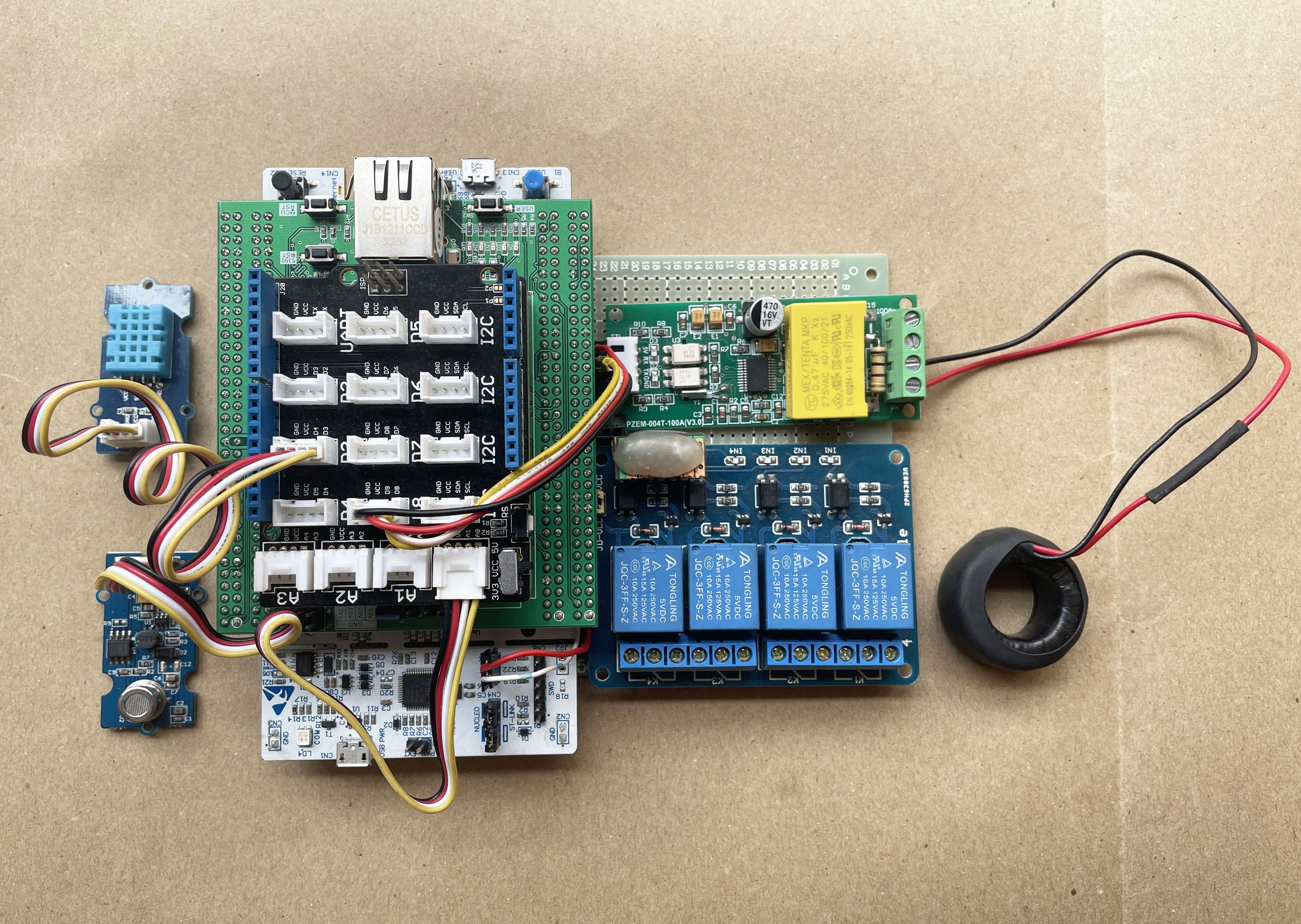
The following photo shows the connections of the sensors.
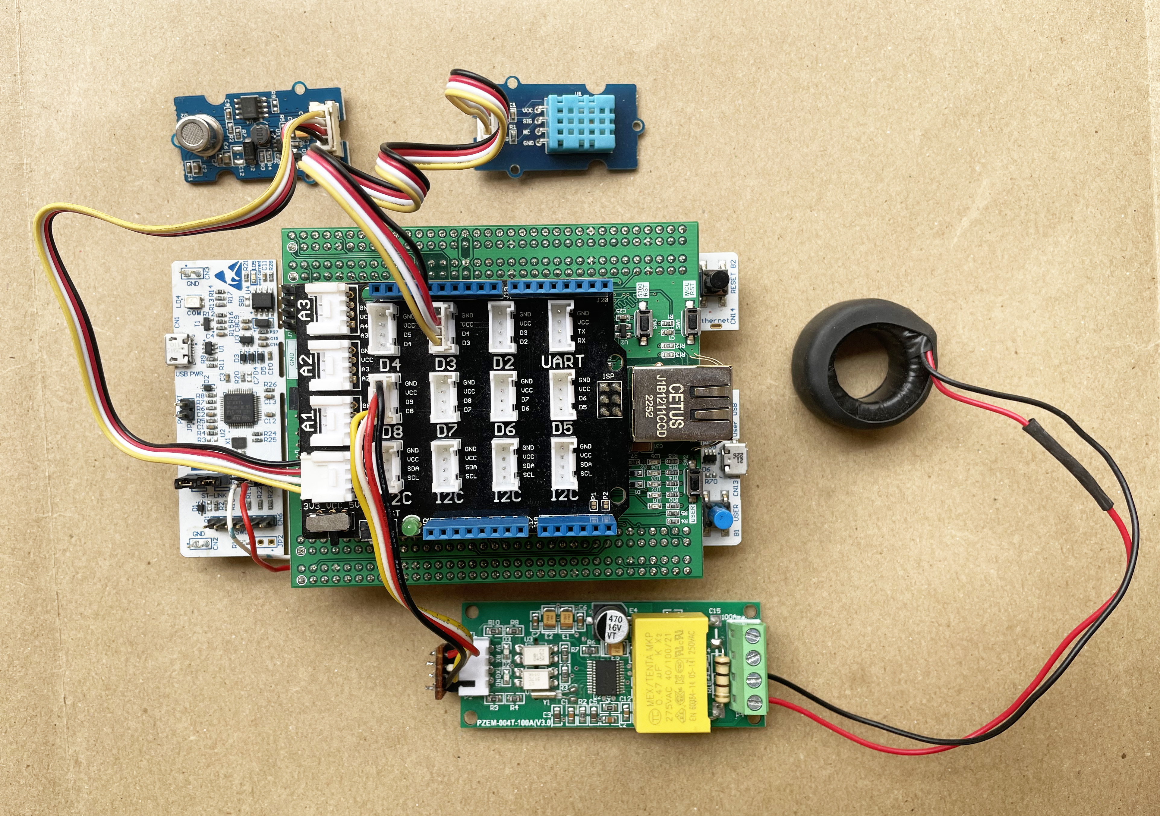
Step 7: Connecting PZEM-004T Power Module
The PZEM-004T module is used to measure Voltage, Current, Power, Energy, Power Factor, Frequency, and Energy consumption without any calculation. It takes the voltage and current readings from CT & PT and does all the calculations for you.
The connection of the module is a bit tricky. The module sense current and voltage from the load and provides the calculated data through the serial port. So, you need to connect the module to the microcontroller through the UART port.
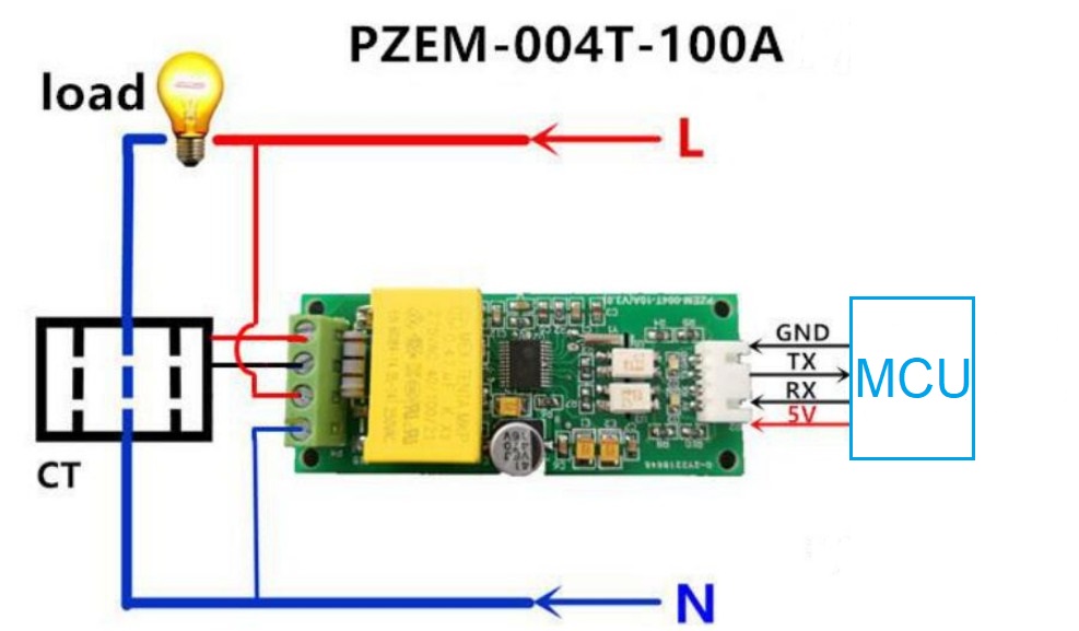
The load side should be connected with the load through CT for current sensing. The above image shows the connection with the load and the microcontroller.
The RX pin of the power module must be connected to the TX pin of the microcontroller and the TX pin of the power module must be connected to the RX pin of the microcontroller. I configured UART6 of the STM32F722ZE microcontroller for connecting the PZEM power module. The UART6 RX pin is PC7 which is the D8 pin of the Arduino header and UART6 TX pin is the PC6 pin which is the D9 of the Arduino header. I used the D8 port of the base shield for connecting the PZEM module.
The following image shows the connection of the PZEM module with the base shield.
Step 8: Connecting Relay Module
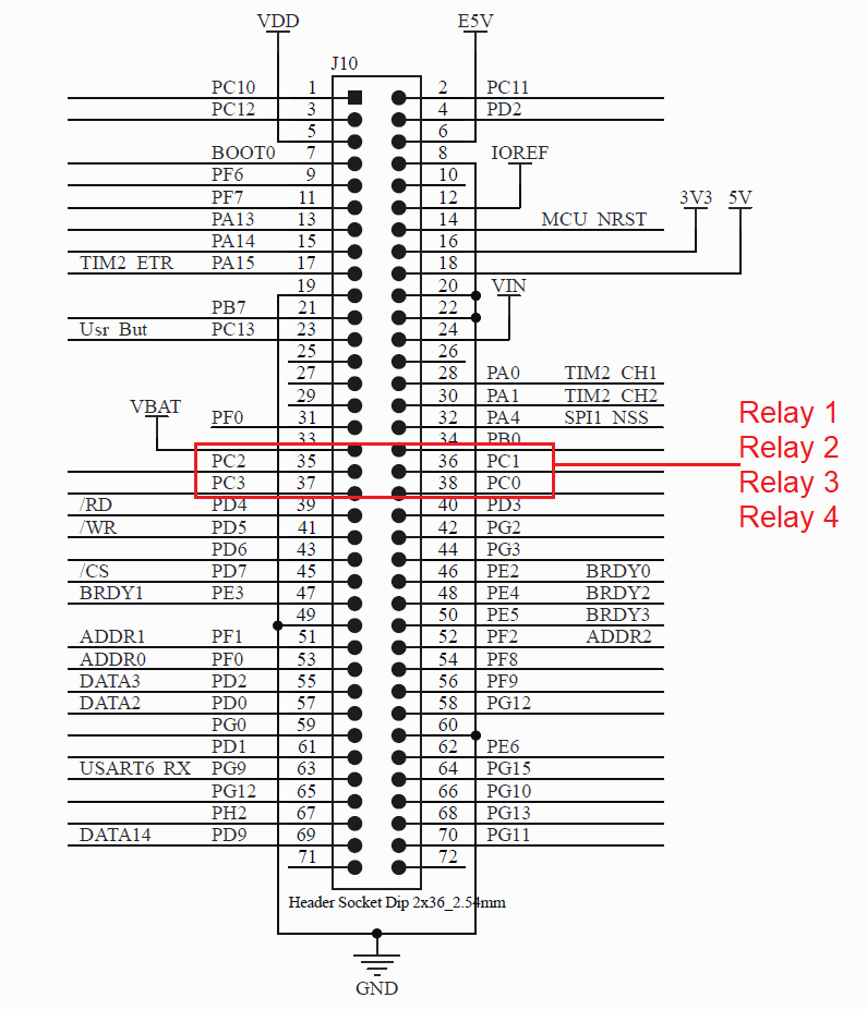
For controlling the home appliances I used 4 channel relay module in the project. Each relay will individually control one appliance. The 4 relay inputs are connected to PC0, PC1, PC2 and PC4 pins of the STM32 microcontroller. These 4 pins are available to J10 header of the W5300 TOE SHIELD. See the following image.
Step 9: Connecting Serial Camera
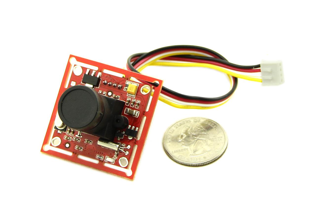
For remote watching inside the room, I attached Grove serial camera. Grove - Serial Camera Kit includes one control board and two interchangeable lenses, one is a standard lens and the other is a wide-angle lens.
The camera communicates with any microcontroller through the serial port. Both RS485 and RS232 are supported. I am using UART7 of the STM32 Nucleo board here for connecting the camera. UART7 is configured in the PF6 and PF7 pins of the microcontroller. These two pins are available at the J10 header connector of the W5300 TOE SHIELD.
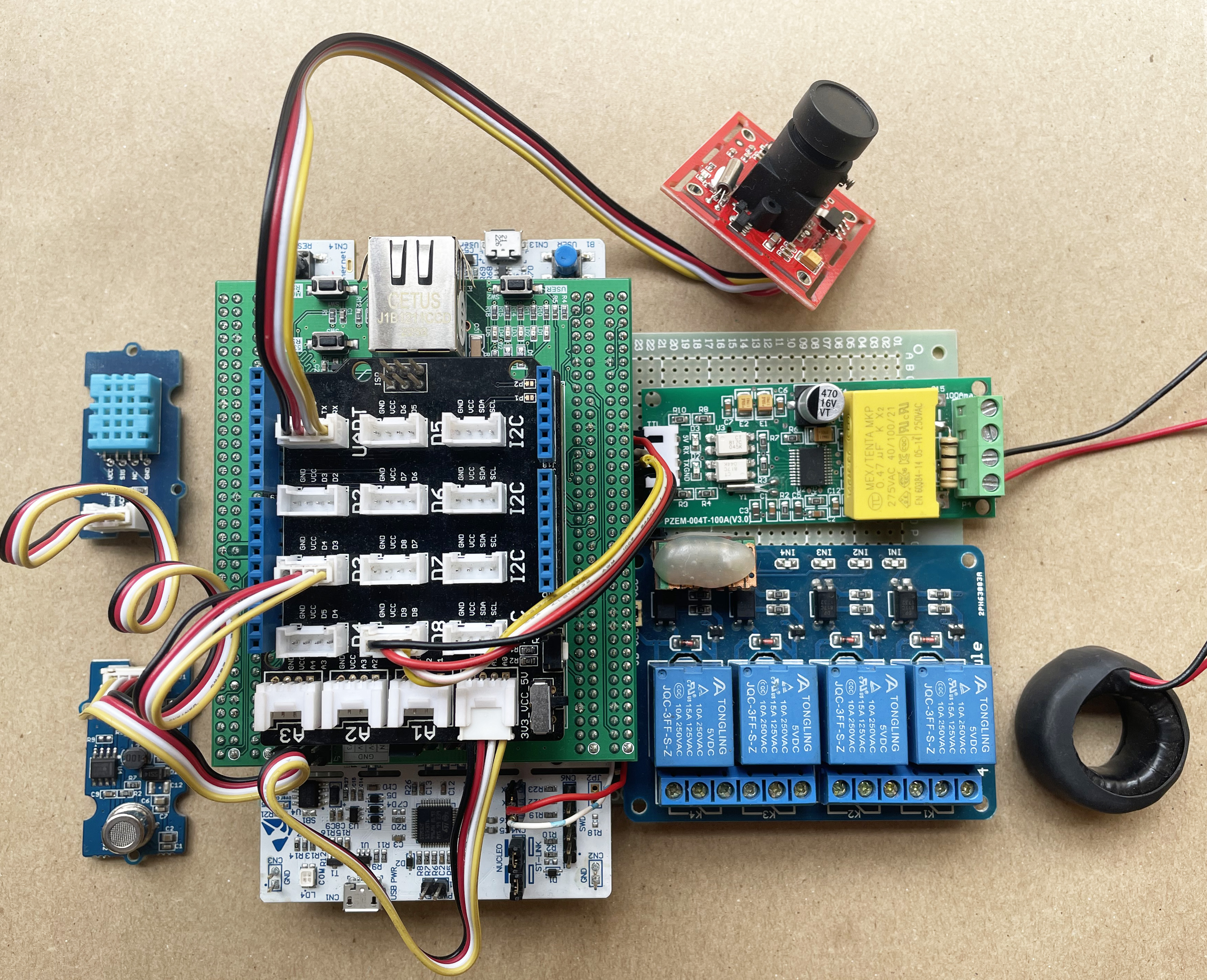
The above image shows the camera connection to the UART port of the base shield.
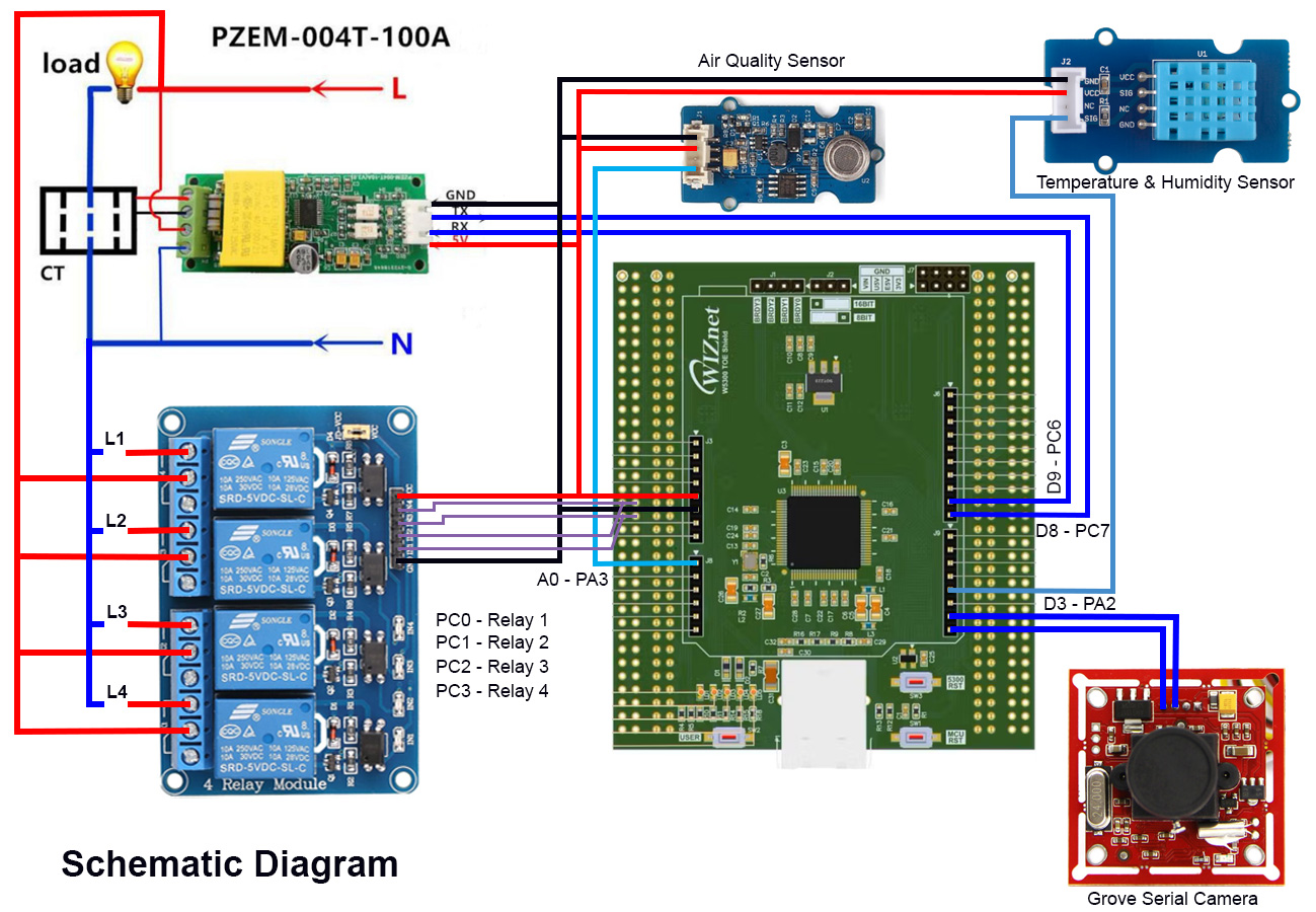
Schematic of the full project
The full schematic of the hardware is as follows:
Firmware Development
Before going to the coding let's discuss how the system works. The brain of the system is the STM32H7 microcontroller. All sensors, ethernet TOE shield, and the camera are directly connected to the STM32 microcontroller. Sensors provide the data to STM32 microcontroller, the microcontroller uses the WIZnet W5300 ethernet module to forward the data to a cloud server using the MQTT protocol. I developed an Android application through which the sensor data can be visualized remotely. Appliances connected with the STM32 microcontroller can also be controlled from the apps. As MQTT is not good for image transfer I have implemented an HTTP server to send image data from the device to the user. Thus users will be able to monitor the inside of the house or plant remotely from the app. If you are new in MQTT let's explain it in brief. A basic understanding of MQTT is required for developing and understanding the firmware program.
MQTT in Brief
MQTT stands for Message Queuing Telemetry Transport and is a simple lightweight messaging protocol created by IBM in 1999. It was primarily designed to create a reliable machine-to-machine (m2m) communication. Now, it becomes the most popular messaging protocol in IoT application for device-to-cloud and device-to-device communication. It is hugely adopted in most of the home automation systems. Nowadays almost all cloud service support MQTT.
We use "client and server" communication technique for serving internet content, where the browser act as a client and the content is on the server. Unlike client-server, MQTT is a "client and broker" communication technique. In MQTT the clients (more accurately the devices) don't send messages directly to each other but instead communicate through a MQTT broker. The device that sends the data is called the publisher and the receiving device is called the subscriber. If two devices want to communicate with each other they become connected to a common broker through a common channel called topic. The word topic refers to an alphanumeric string that the broker uses to filter messages for each connected client. The topic consists of one or more topic levels. Each topic level is separated by a forward slash (topic level separator). For example "myhome/kitchen/temp" is a valid MQTT topic. Messages are published by things using a topic. When a thing subscribes to a specific topic that device receives the message instantly if other devices publish a message in that topic. Any device can publish to one or more topics and at the same time, it can subscribe to one or more topics. So, it is a bidirectional multi-device communication protocol. MQTT broker takes care of the security, connectivity, authentication, message delivery, and message storage. For learning more about MQTT protocol visit hivemq.com/mqtt-protocol.
The above section explained the basics of MQTT but as a maker you may ask, how do we actually use it in a device? Every MQTT broker has an address (e.g. test.mosquitto.org) and a port number (e.g. 1883). We use an address and a port number of a broker to set them on the IoT device to connect to that specific broker. For a secure connection, you may also need to use a username and password. For publishing a message you then create and use a topic in the program. The device that wants to receive that message must subscribe to this specific topic.
For example, in this project, I am subscribing "taifur/home/data" topic from the Android application to receive the sensor data from the hardware device. At the same time, I am publishing some messages to the device from the Android apps to control the appliances at "taifur/home/command" topic. From the device, I am subscribed to that topic.
Transferring image
As MQTT is a lightweight protocol it is not a good choice for publishing images. So, I implemented an HTTP server for showing images of the house to the user remotely. HTTP is a client-server communication technique where the Android app sends a GET request to the HTTP server for the image on a button press. The server returns back the image to the client.
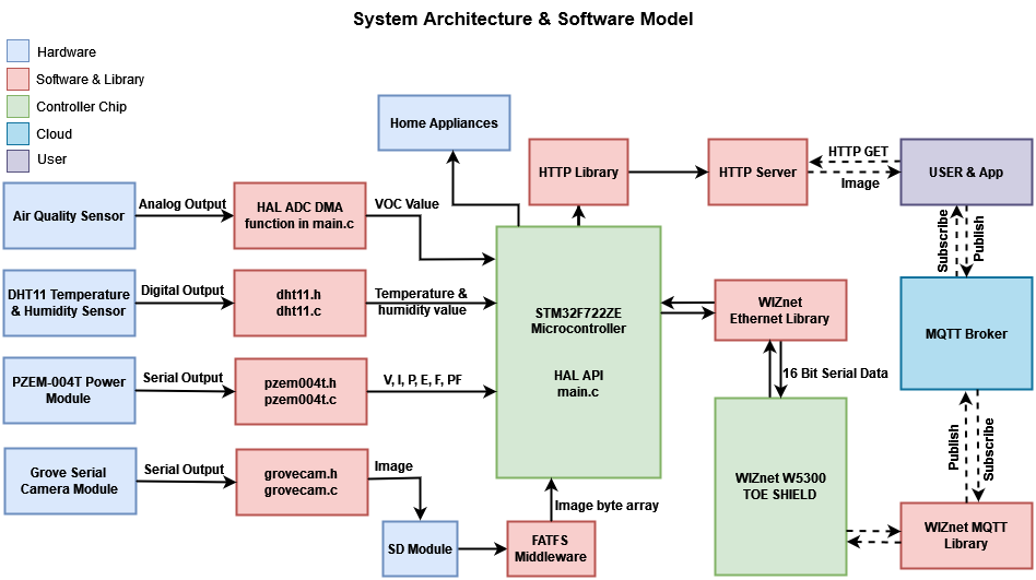
The Software Model
From the above image, you will observe that I have shown the related source file and library separately for every hardware for better understanding. I tried to make the source file of a specific sensor independent of other sensors or hardware so that you can reuse the source files for your other project.
For example, dht11.h and dht11.c are exclusively related to the reading of the temperature and humidity value from the DHT11 sensor. These two source files are completely independent of other sources. You can directly use these two source files for any of your STM32 projects for interfacing a DHT11 sensor. The same is true for PZEM-004T and Grove Serial Camera Module.
Storing images captured from the camera required an SD card. For SD interfacing I am using FATFS middleware. For giving Internet connectivity in the project Wiznet W5300 TOE Shield is used. This module requires communication to the microcontroller and WIZnet provided Ethernet library was used for this purpose. For MQTT communication I modified and used WIZnet provided MQTT library. I did the same for implementing the HTTP server.
Enough talk. Now let's show how I actually developed the firmware. I choose the STM32CubeIDE for the firmware development. And I get started with the code provided by the WIZnet in the GitHub link: https://github.com/Wiznet/W5300-TOE-C/.
Step 1: Downloading & Installing STM32CubeIDE
I downloaded the STM32CubeIDE from the link:https://www.st.com/en/development-tools/stm32cubeide.html and installed it on my Windows PC. Installing is very straightforward.
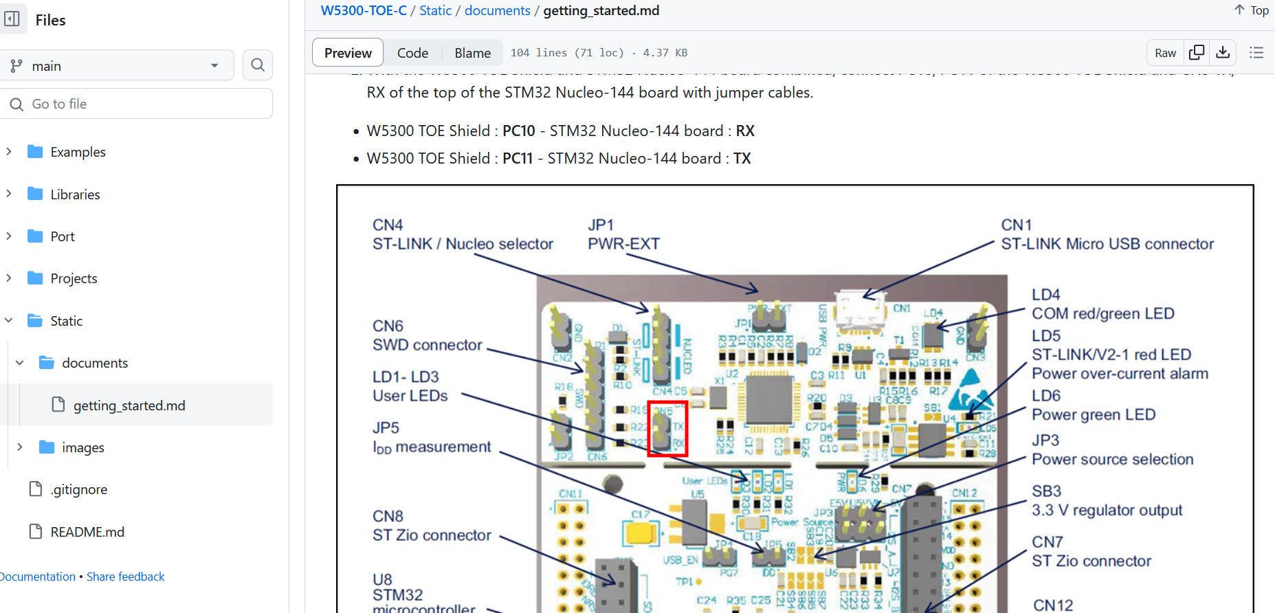
Step 2: Downloading necessary library and code sample
I downloaded the GitHub repository provided by the WIZnet from the link: https://github.com/Wiznet/W5300-TOE-C/. This repository contains all the required libraries for the W5300 TOE SHIELD, datasheet, schematic, getting started guide, and example project. The following image shows a screenshot of the GitHub getting started guide.
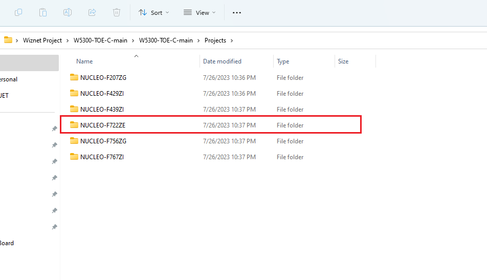
Step 3: Creating the first project
I started my project by opening the example project from GitHub for my specific board. Choose the right one based on your STM32 Nucleo board.
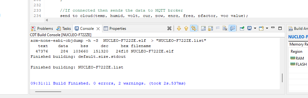
Step 4: Building the project
After importing and opening the project I recommend building the project before starting any modification so that we can get sure that everything is working.
Step 5: Adding the required libraries to the project
For working with the W5300 TOE SHIELD we need to include a few libraries in our project.
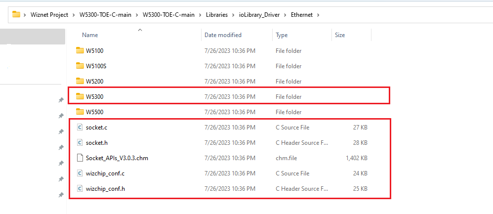
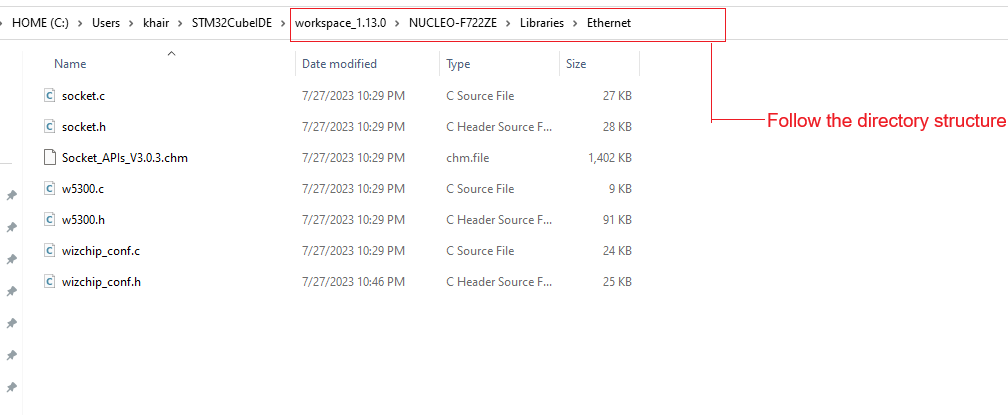
Step 5.1: Adding Ethernet library
The ethernet library is provided in the Github repositories. I copied the W5300 folder and other files as shown in the screenshot (1st) below and pasted those in my project workspace folder shown in the 2nd screenshot.
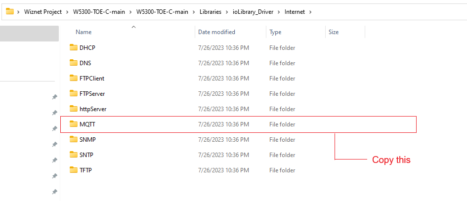
Step 5.2: Adding MQTT library
From the Github repository folder, I copied the MQTT directory as shown in the screenshot (1st) and pasted it to my project workspace shown in the screenshot (2nd) below.
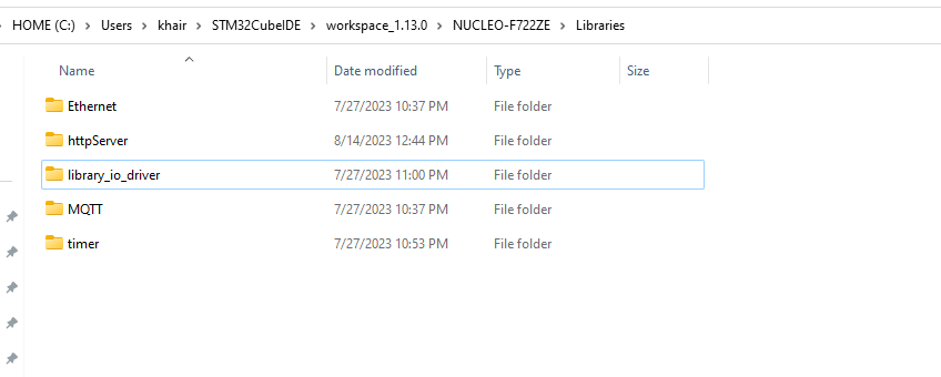
Step 5.3: Adding others
Using the same procedure I also added httpServer, timer, and library_io_driver to my project directory as illustrated in the above screenshot.
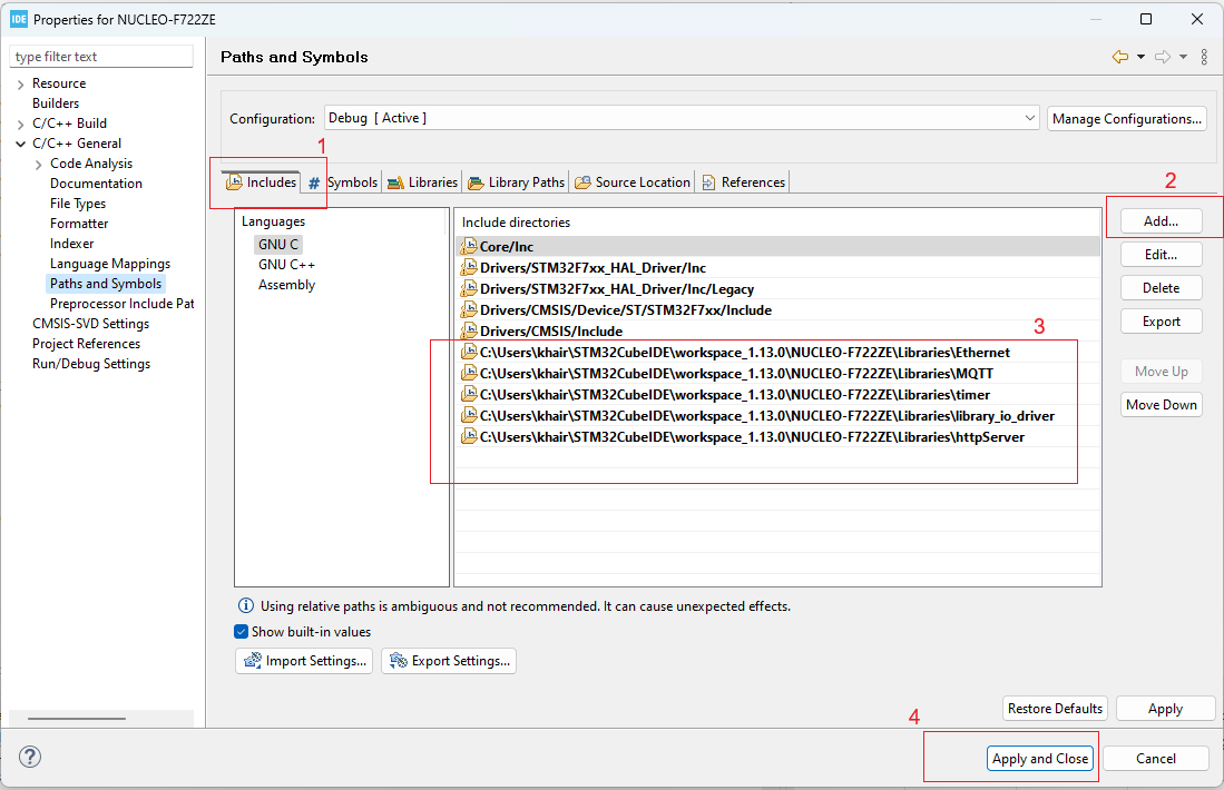
Step 6: Adding the path of the library
Now we need to add the path of all the added libraries so that the build system can recognize the files we added. To do that I open the project properties window and added the path of all the directories I added in my project workspace from the Includes tab as shown in the following screenshot.
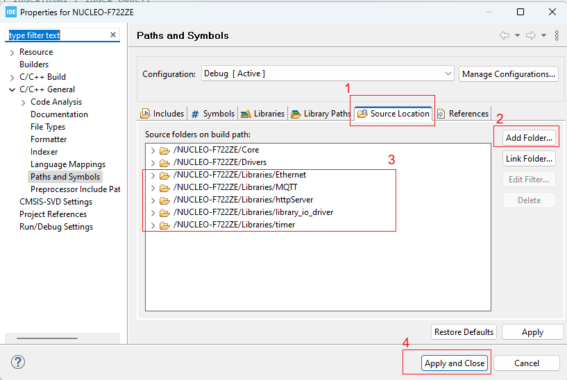
In the same way, you need to add the source location as shown in the screenshot below.
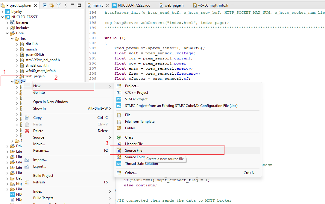
Step 7: Adding new source file to the project
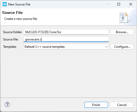
For a custom library or custom source, you need to add a new source to your project by creating an empty source file. Just right-click on the Src folder from Project Explorer window, and from the New dropdown click on Source File submenu as shown in the image below.
A new window will be open. Give a unique name of the new source file and click on Finish.
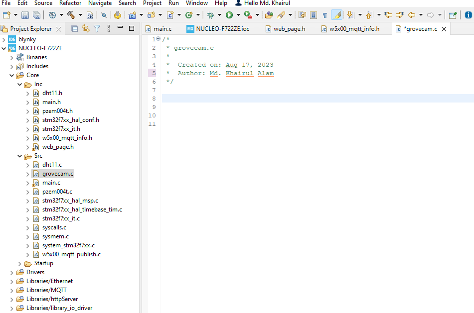
A new source file will be created and opened automatically. Write or add your own code here.
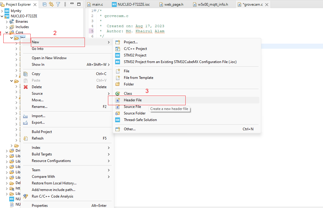
For adding a new header file right-click on the Inc folder and from the New dropdown choose Header File. A new window will be opened.
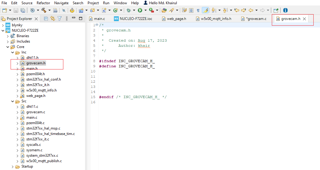
Give a name of the header file and click on Finish. The new header file will be created and opened. Add your own code here.
Following the above procedure I created dht11.h and dht11.c for temperature and humidity sensor, pzem004t.h and pzem004t.c for power module, grovecam.h and grovecam.c for the grove camera.
Step 8: Copying source file to the project directory
In a previous step, I showed how I added MQTT library from the Wiznet GitHub repository to my project directory. But for MQTT communication just a library is not enough. I need custom code for publishing and subscribing MQTT messages to MQTT broker. For this purpose, I added MQTT example code from the same GitHub project to my project.
From W5300-TOE-C-main -> Example -> mqtt I copied the source from the publish directory and pasted it to my project Core -> Src folder.
From:
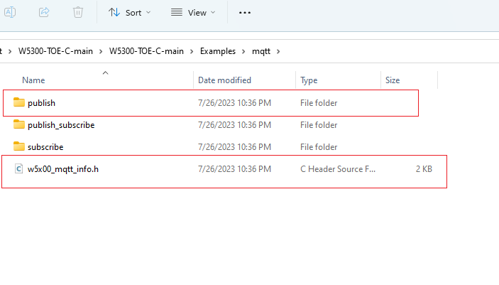
To:
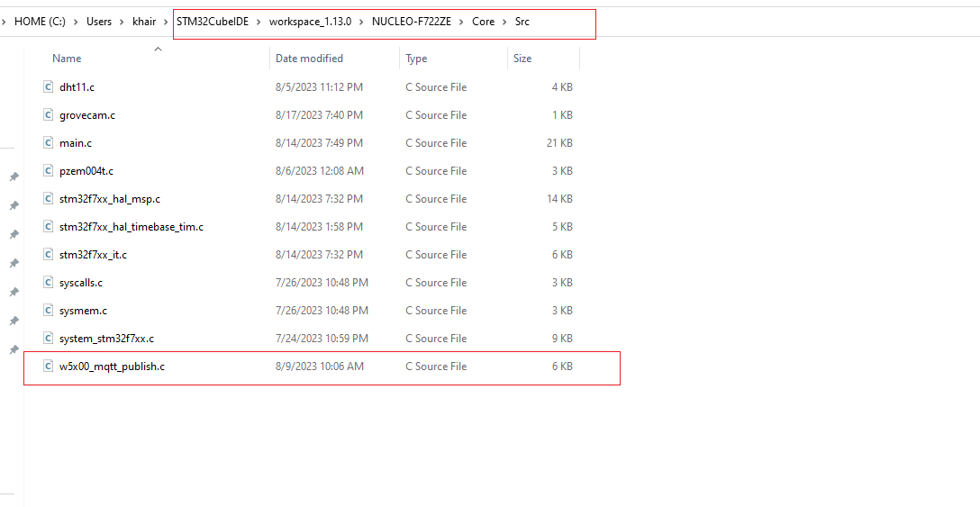
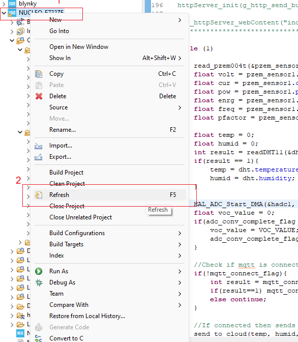
Similarly, I copied w5x00_mqtt_info.h to the Core -> Inc folder. Now will find and access the files from your CubeIDE. If you don't see the files just click on Refresh.
Now, you are ready to modify the files according to your requirement. For example, I modified the source file as follows.
/**
 * Copyright (c) 2023 WIZnet Co.,Ltd
 *
 * SPDX-License-Identifier: BSD-3-Clause
 */

/*
 * ----------------------------------------------------------------------------------------------------
 * Includes
 * ----------------------------------------------------------------------------------------------------
 */
#include "main.h"
#include <stdio.h>
#include <string.h>

#include "wizchip_conf.h"
#include "w5x00_network.h"
#include "w5x00_timer.h"
#include "w5x00_mqtt_info.h"

#include "mqtt_interface.h"
#include "MQTTClient.h"

/*
 * ----------------------------------------------------------------------------------------------------
 * Macros
 * ----------------------------------------------------------------------------------------------------
 */

/*
 * ----------------------------------------------------------------------------------------------------
 * Variables
 * ----------------------------------------------------------------------------------------------------
 */
static uint8_t g_mqtt_send_buf[ETHERNET_BUF_MAX_SIZE] = {
    0,
};
static uint8_t g_mqtt_recv_buf[ETHERNET_BUF_MAX_SIZE] = {
    0,
};
static uint8_t g_mqtt_broker_ip[4] = {91, 121, 93, 94};  //public ip of eclipse broker.emqx.org
static Network g_mqtt_network;
static MQTTClient g_mqtt_client;
static MQTTPacket_connectData g_mqtt_packet_connect_data = MQTTPacket_connectData_initializer;
static MQTTMessage g_mqtt_message;

/**
 * ----------------------------------------------------------------------------------------------------
 * Functions
 * ----------------------------------------------------------------------------------------------------
 */

static void repeating_timer_callback(void)
{
  MilliTimer_Handler();
}


static void message_arrived(MessageData *msg_data)
{
  MQTTMessage *message = msg_data->message;

  printf("%.*s receive\n", (uint32_t)message->payloadlen, (uint8_t *)message->payload);

  char *command = message->payload;

  if(strcmp(command, "R1ON") == 0){
	 printf("relay 1 on\n");
	 HAL_GPIO_WritePin(RELAY_1_GPIO_Port, RELAY_1_Pin, GPIO_PIN_SET);
	 return;
  }

  if(strcmp(command, "R1OF") == 0){
	 printf("relay 1 off\n");
  	 HAL_GPIO_WritePin(RELAY_1_GPIO_Port, RELAY_1_Pin, GPIO_PIN_RESET);
	 return;
  }

  if(strcmp(command, "R2ON") == 0){
	 printf("relay 2 on\n");
  	 HAL_GPIO_WritePin(RELAY_2_GPIO_Port, RELAY_2_Pin, GPIO_PIN_SET);
	 return;
  }

  if(strcmp(command, "R2OF") == 0){
	 printf("relay 2 off\n");
     HAL_GPIO_WritePin(RELAY_2_GPIO_Port, RELAY_2_Pin, GPIO_PIN_RESET);
	 return;
  }

  if(strcmp(message->payload, "R3ON") == 0){
	 printf("relay 3 on\n");
  	 HAL_GPIO_WritePin(RELAY_3_GPIO_Port, RELAY_3_Pin, GPIO_PIN_SET);
  	 return;
  }

  if(strcmp(message->payload, "R3OF") == 0){
	 printf("relay 3 off\n");
     HAL_GPIO_WritePin(RELAY_3_GPIO_Port, RELAY_3_Pin, GPIO_PIN_RESET);
     return;
  }

  if(strcmp(message->payload, "R4ON") == 0){
	 printf("relay 4 on\n");
  	 HAL_GPIO_WritePin(RELAY_4_GPIO_Port, RELAY_4_Pin, GPIO_PIN_SET);
  	 return;
  }

  if(strcmp(message->payload, "R4OF") == 0){
	 printf("relay 4 off\n");
     HAL_GPIO_WritePin(RELAY_4_GPIO_Port, RELAY_4_Pin, GPIO_PIN_RESET);
     return;
  }

  if(strcmp(message->payload, "RAON") == 0){
	 printf("relay all on\n");
  	 HAL_GPIO_WritePin(RELAY_1_GPIO_Port, RELAY_1_Pin, GPIO_PIN_SET);
  	 HAL_GPIO_WritePin(RELAY_2_GPIO_Port, RELAY_2_Pin, GPIO_PIN_SET);
  	 HAL_GPIO_WritePin(RELAY_3_GPIO_Port, RELAY_3_Pin, GPIO_PIN_SET);
  	 HAL_GPIO_WritePin(RELAY_4_GPIO_Port, RELAY_4_Pin, GPIO_PIN_SET);
  	 return;
  }

  if(strcmp(message->payload, "RAOF") == 0){
	 printf("relay all off\n");
     HAL_GPIO_WritePin(RELAY_1_GPIO_Port, RELAY_1_Pin, GPIO_PIN_RESET);
     HAL_GPIO_WritePin(RELAY_2_GPIO_Port, RELAY_2_Pin, GPIO_PIN_RESET);
     HAL_GPIO_WritePin(RELAY_3_GPIO_Port, RELAY_3_Pin, GPIO_PIN_RESET);
     HAL_GPIO_WritePin(RELAY_4_GPIO_Port, RELAY_4_Pin, GPIO_PIN_RESET);
  }

}


uint8_t mqtt_connect(wiz_NetInfo *net_info)
{
  int retval = 0;

  wizchip_network_initialize(net_info);
  wizchip_network_information(net_info);

  NewNetwork(&g_mqtt_network, SOCKET_MQTT);

  retval = ConnectNetwork(&g_mqtt_network, g_mqtt_broker_ip, PORT_MQTT);

  if (retval != 1)
  {
    printf(" Network connect failed\n");

  }

  MQTTClientInit(&g_mqtt_client, &g_mqtt_network, MQTT_TIMEOUT, g_mqtt_send_buf, ETHERNET_BUF_MAX_SIZE, g_mqtt_recv_buf, ETHERNET_BUF_MAX_SIZE);

  g_mqtt_packet_connect_data.MQTTVersion = 3;
  g_mqtt_packet_connect_data.cleansession = 1;
  g_mqtt_packet_connect_data.willFlag = 0;
  g_mqtt_packet_connect_data.keepAliveInterval = MQTT_KEEP_ALIVE;
  g_mqtt_packet_connect_data.clientID.cstring = MQTT_CLIENT_ID;
  g_mqtt_packet_connect_data.username.cstring = MQTT_USERNAME;
  g_mqtt_packet_connect_data.password.cstring = MQTT_PASSWORD;

  retval = MQTTConnect(&g_mqtt_client, &g_mqtt_packet_connect_data);

  if (retval < 0)
  {
    printf(" MQTT connect failed : %d\n", retval);
    return 0;

  }

  printf(" MQTT connected\n");
  return 1;

}


void mqtt_publish(char *new_message)
{
  int retval = 0;

  g_mqtt_message.qos = QOS0;
  g_mqtt_message.retained = 0;
  g_mqtt_message.dup = 0;
  //g_mqtt_message.payload = MQTT_PUBLISH_PAYLOAD;
  g_mqtt_message.payload = new_message;
  g_mqtt_message.payloadlen = strlen(g_mqtt_message.payload);


  if ((retval = MQTTYield(&g_mqtt_client, g_mqtt_packet_connect_data.keepAliveInterval)) < 0)
  {
     printf(" Yield error : %d\n", retval);
  }

  retval = MQTTPublish(&g_mqtt_client, MQTT_PUBLISH_TOPIC, &g_mqtt_message);

  if (retval < 0)
  {
     printf(" Publish failed : %d\n", retval);
  }

  printf(" Published\n");
}


void mqtt_subscribe(wiz_NetInfo *net_info)
{
  int retval = 0;

  wizchip_1msec_timer_initialize(repeating_timer_callback);

  retval = MQTTSubscribe(&g_mqtt_client, MQTT_SUBSCRIBE_TOPIC, QOS0, message_arrived);

  if (retval < 0)
  {
    printf(" Subscribe failed : %d\n", retval);
  }

  printf(" Subscribed\n");

}
Step 9: Adding SD card support to my project
As I am using a camera for my project I need an SD card for storing images. And for reading and writing images in SD card a file system library is required. I am using FATFS middleware in my project. In this step, I will show you how I added and configured the FATFS middleware in my project.
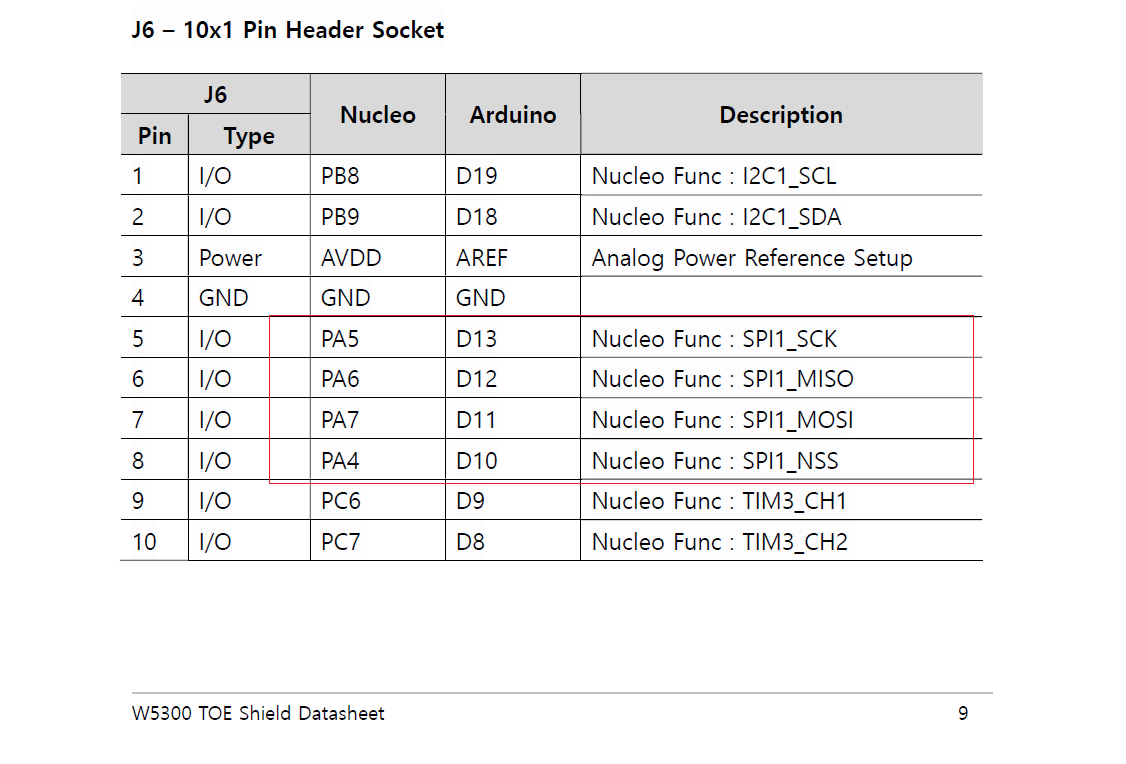
I have an Arduino SD card shield and for this reason, my intention was to use the Arduino header of the TOE shield for SD card interfacing. The SD card shield uses SPI protocol for communication with microcontroller. So, I was looking at which SPI port Wiznet W5300 TOE SHIELD utilizes. I looked in the TOE Shield datasheet and on page 9 I found the following table. From the table, I understand that the Arduino header uses SPI1.
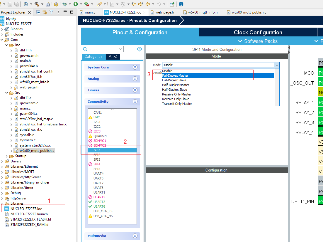
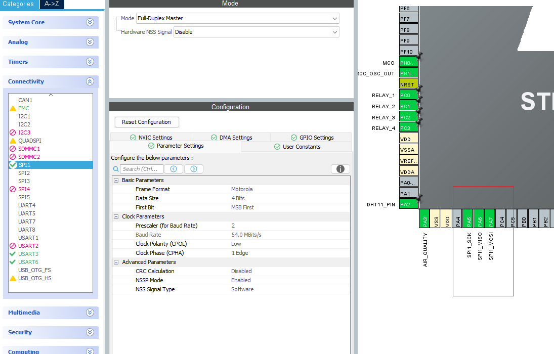
I kept the SPI configuration as default.
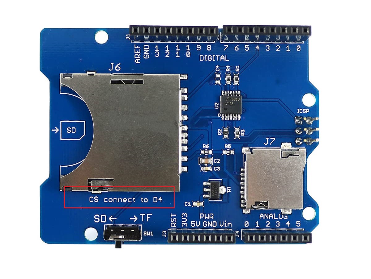
As the SD card shield uses D4 as CS, I looked at that datasheet again for finding the D4 connected pin for the microcontroller.
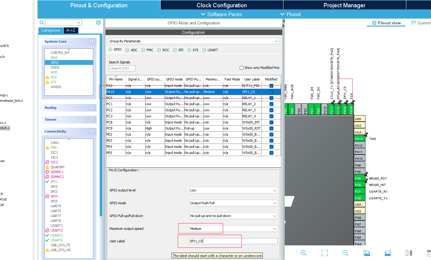
From page 6 of the datasheet, I found that D4 is actually the PA15 pin of the STM32 Nucleo board.
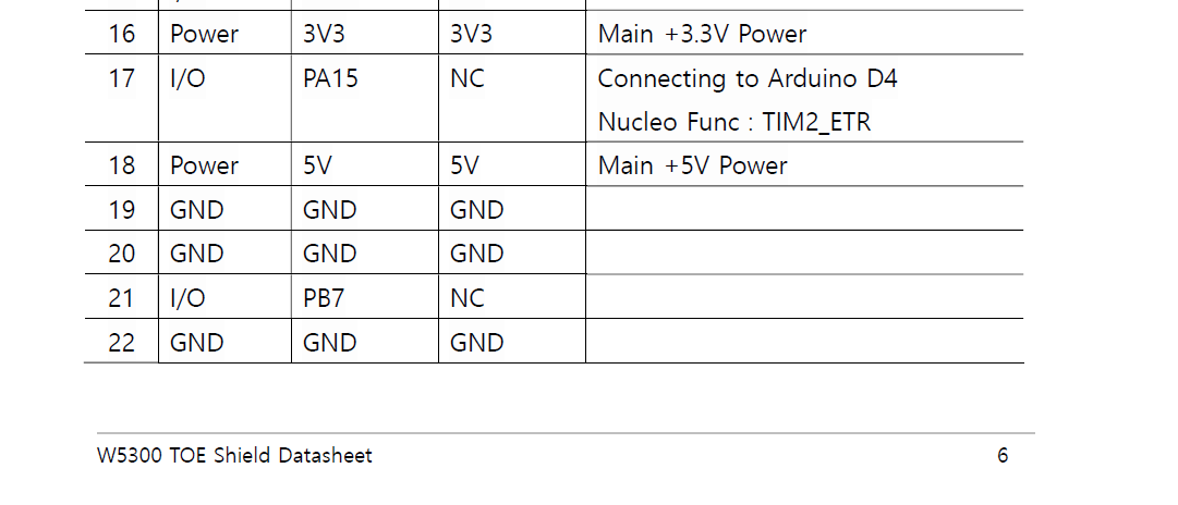
So, I configured the PA15 pin as output and renamed it as SPI1_CS.
Then I enabled the FATFS middleware as User-defined mode with two configuration changes as shown in the following image.
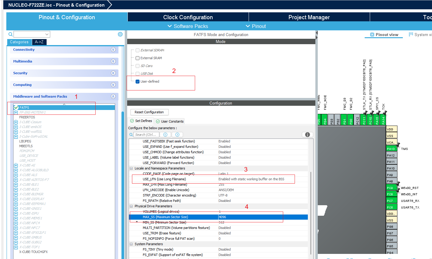
Finally, I saved the configuration and allow it to generate the code.
For completing this part I strongly recommend to watch this youtube video:
And follow this Github: https://github.com/eziya/STM32_SPI_SDCARD/tree/master.
This is the configuration of the fatfs_sd.h for my case:
extern SPI_HandleTypeDef 	hspi1;
#define HSPI_SDCARD		 	&hspi1
#define	SD_CS_PORT			GPIOA
#define SD_CS_PIN			GPIO_PIN_15
The final project structure is shown in the screenshot below.
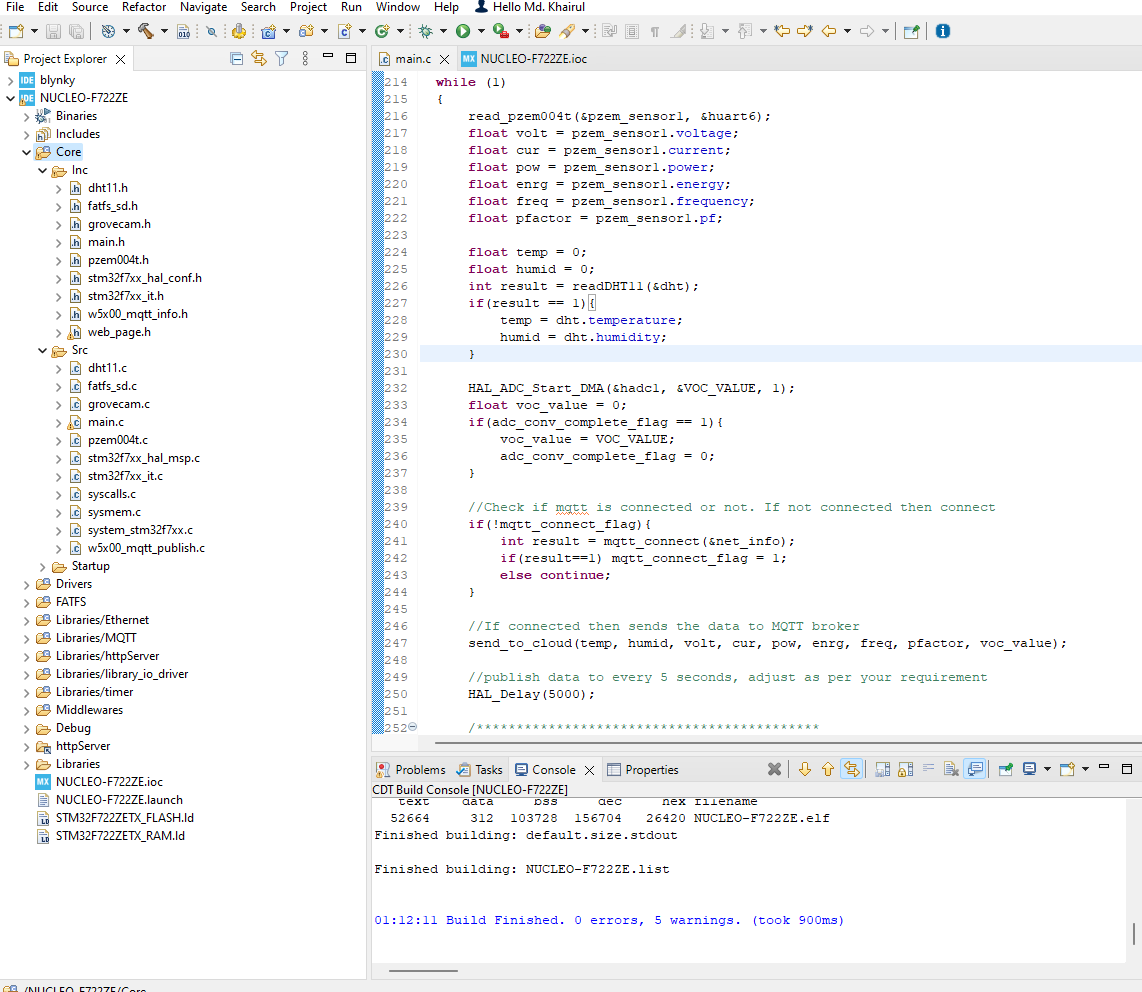
The full source code is provided in GitHub: https://github.com/taifur20/smart_home_hub
You can directly download the repository and open it with STM32CubeIDE. After opening you can build the project and run it in your STM32F722ZE Nucleo board.
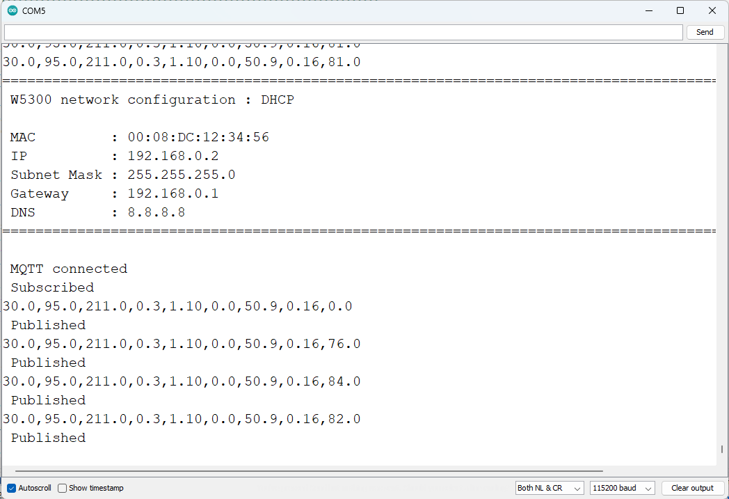
You can check the response in the serial terminal after connecting all the sensors. After a successful connection with Inetrnet & MQTT server, I got the following response in the serial terminal. I used the Arduino serial terminal. You can use any serial terminal you like.
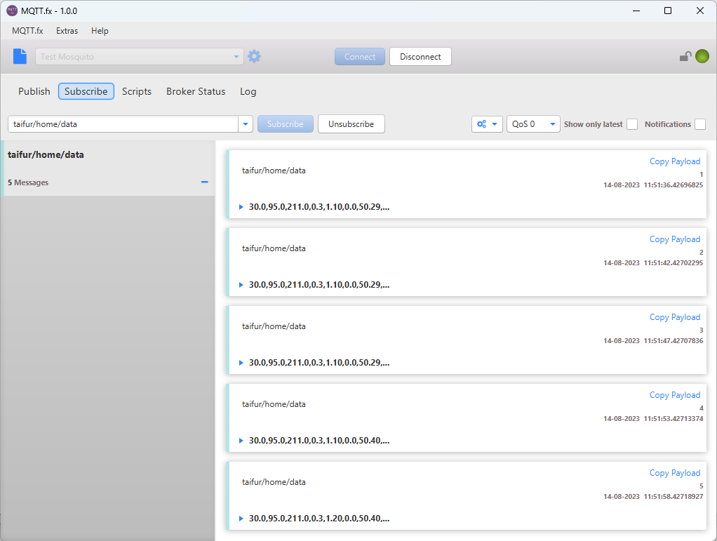
For testing MQTT message is publishing and receiving successfully you can use MQTT.fx tool. Here is the response I got.
Reusing the Code
I have tried to keep the code of one hardware or sensor independent from other hardware. For this reason, I made separate source files for every sensor and hardware. That will help you to easily copy the related source file for a specific sensor or hardware from this project to any other project you like to make using that specific hardware module. The schematic is also very simple and you can easily implement a part of it for other projects.
Android Application Development
I developed an Android application for remote monitoring and control of my home. Through the apps, the status of each appliance with the details power profile can be observed. For developing the Android application I used kodular.io online platform. This is a platform like MIT App Inventor and by using this platform you can develop an Android application with a single line of code. I added the source code for the application in the attachment section. You can modify it by opening it either in kodular.io or appinventor.mit.edu.
The following image shows the development phase of the app in kodular.
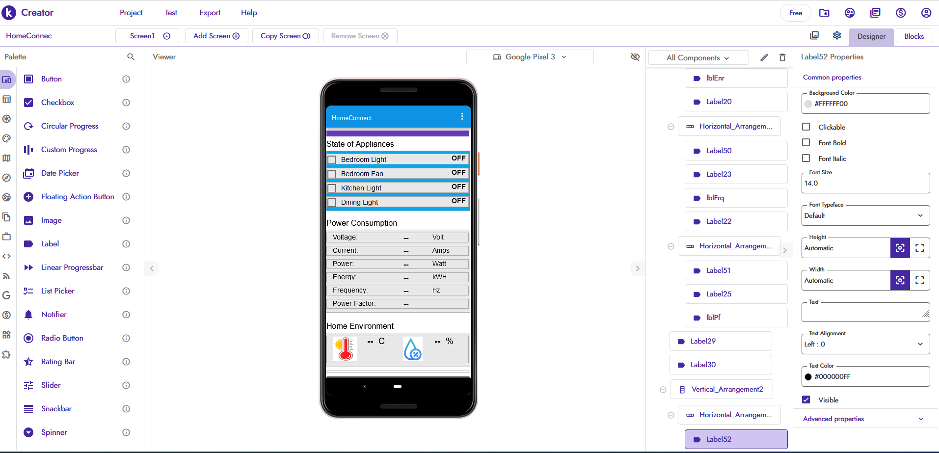
App inventor or kodular uses a graphical user interface (GUI) very similar to the programming languages Scratch and StarLogo, which allows users to drag and drop visual objects (called blocks) to create an application that can be tested on Android and iOS devices. Both of these use a companion mobile app that allows for instant live testing and debugging.
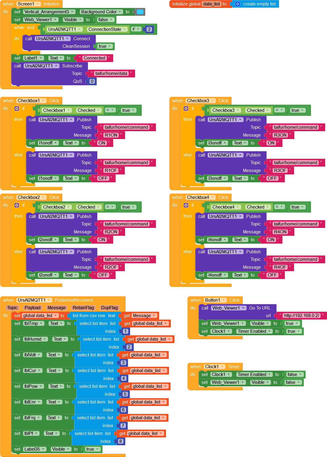
The complete block of my design is given below.
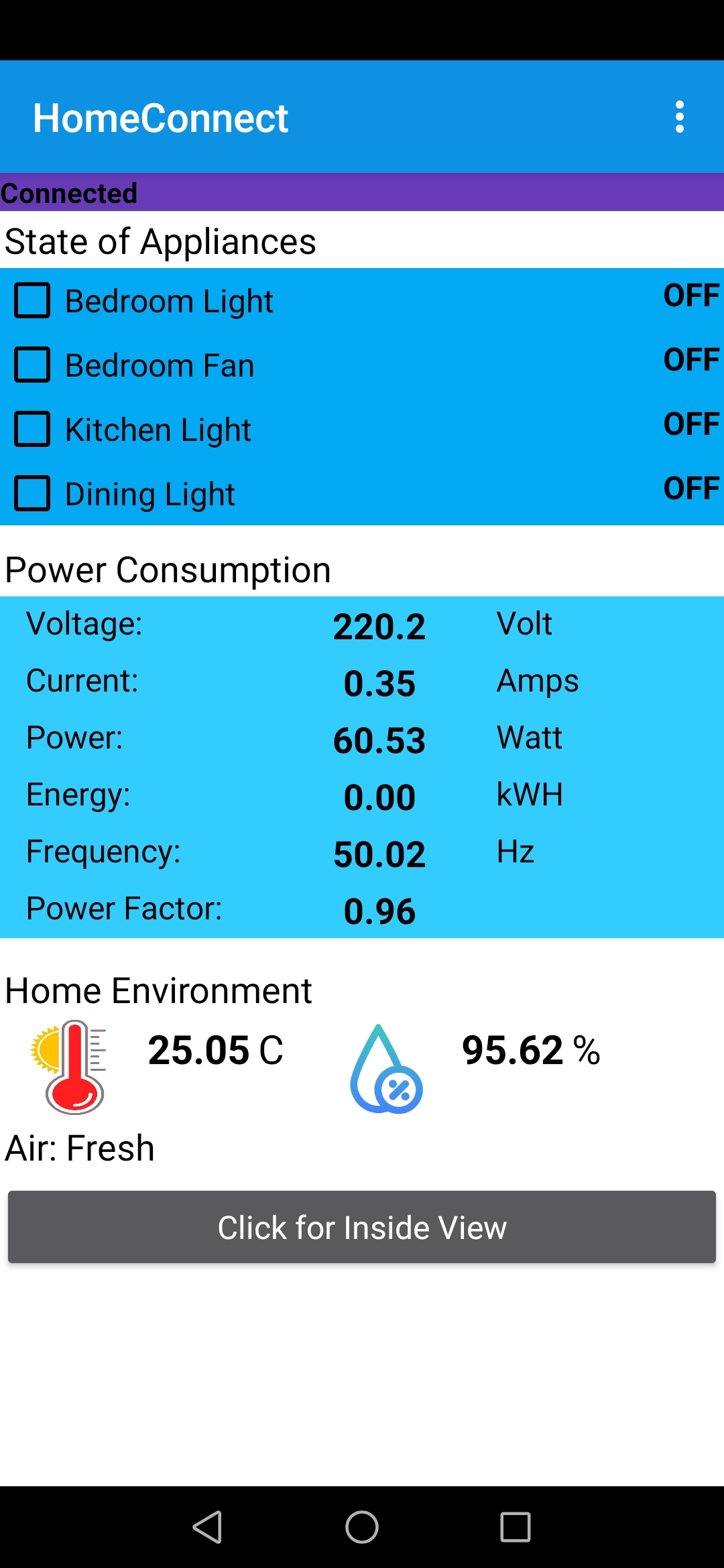
The following image is a screenshot of the application.
Making a Web Dashboard to Visualize the Data
Visualization is an important part of any IoT application. It is always advantageous to watch data remotely and IoT made it easy for us. In this section, I will explain how we can visualize the data using Node-RED.
A Brief about Node-RED
Node-RED is a free and open-source graphical programming tool primarily designed for the Internet of Things that allows programmers of any level to interconnect physical things, cloud-based systems, databases, and APIs to build applications using a web interface and it requires very little, if any, programming knowledge.
With Node-RED we can easily design our own IoT system(s) through which sensors data flow. As the data flows through the system of connected nodes it triggers and performs actions defined by nodes. One can compare Node-RED to a typical water system. A water system may have various types of nodes such as valves, power generators, water heaters, pumps, fountains etc. so as the water flows it activates those nodes to change the water flow as well as water itself or to make some external actions out of the system.
So does Node-RED with the data. As the data flows through the system of connected nodes, it passes data in a sequence from one node to another. Each node acts on the data and performs some actions and passes it further. There are many types of nodes available which allow data to be: filtered; visualised on custom dashboards; stored in database/filesystem, sent as notifications such as email, Twitter etc. it literally gives us endless possibilities of what we can do to integrate the data flow with other software and internet services. Big advantage is we can set this system up in our local network without relying on the internet service providers.
Node-RED allows developers to connect predefined code blocks known as 'nodes' together to perform a task. The connected nodes usually a combination of input nodes, processing nodes, and output nodes when wired together, make up an application program called 'flow'. There are lots of nodes available to perform simple and complex tasks, including web access, Twitter, E-mail, HTTP, UDP, MQTT, controlling GPIO ports, making graphical dashboards, etc. With lots of built-in node you can also install third-party nodes, just like we install third-party libraries in Arduino. Besides visual capability, Node-RED also allows you a lot of functional control (similar to custom functions in a text language) through JavaScript. JavaScript is the programming language that is underlying Node-RED.
Before working with Node-RED first we need to install the Node-RED and it is easy to install Node-RED in a Raspberry Pi.
You can find the most up-to-date official instructions how to install Node-RED on RPi here: https://nodered.org/docs/getting-started/raspberrypi
You can install Node-RED by running the following command in the terminal. This command will download and run a script provided by Node-RED authority to install Node.js, npm and Node-RED onto a Raspberry Pi.
bash <(curl -sL https://raw.githubusercontent.com/node-red/linux-installers/master/deb/update-nodejs-and-nodered)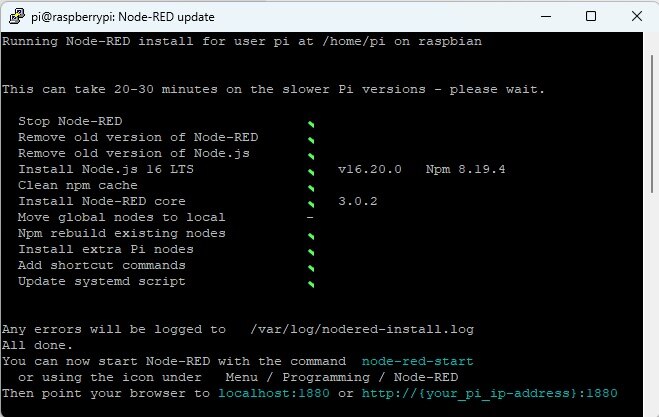
After installing the Node-RED you need to start it. There are different ways to start the Node-RED but the easiest is to run the following command:
node-red-startBelow is the terminal response after running the above command.
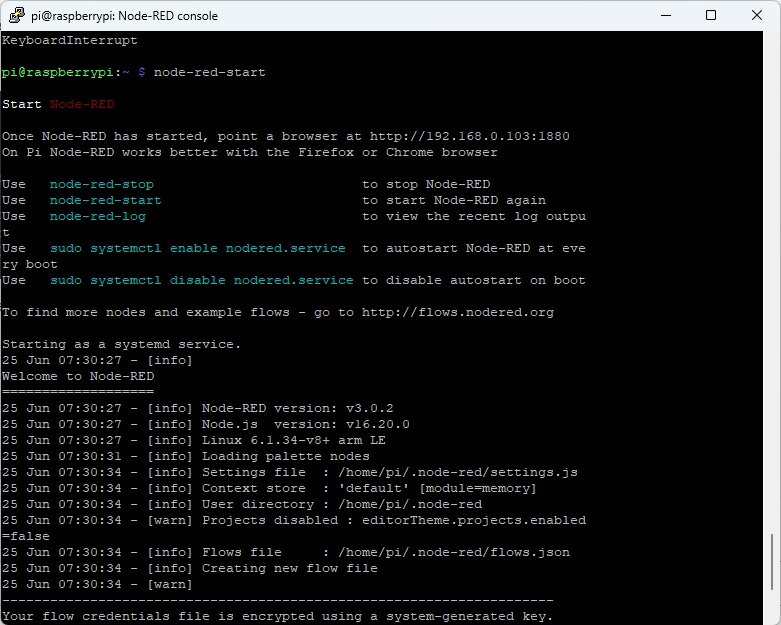
Now, you can open the Node-RED web editor by going to the following URL in your favorite web browser from any computer/phone connected to same network as the Pi.
http://{your_pi_ip-address}:1880
In order to get the ip of your RPi use this command:
hostname -I
If everything works correctly, you should now be greeted by the screen shown in below:
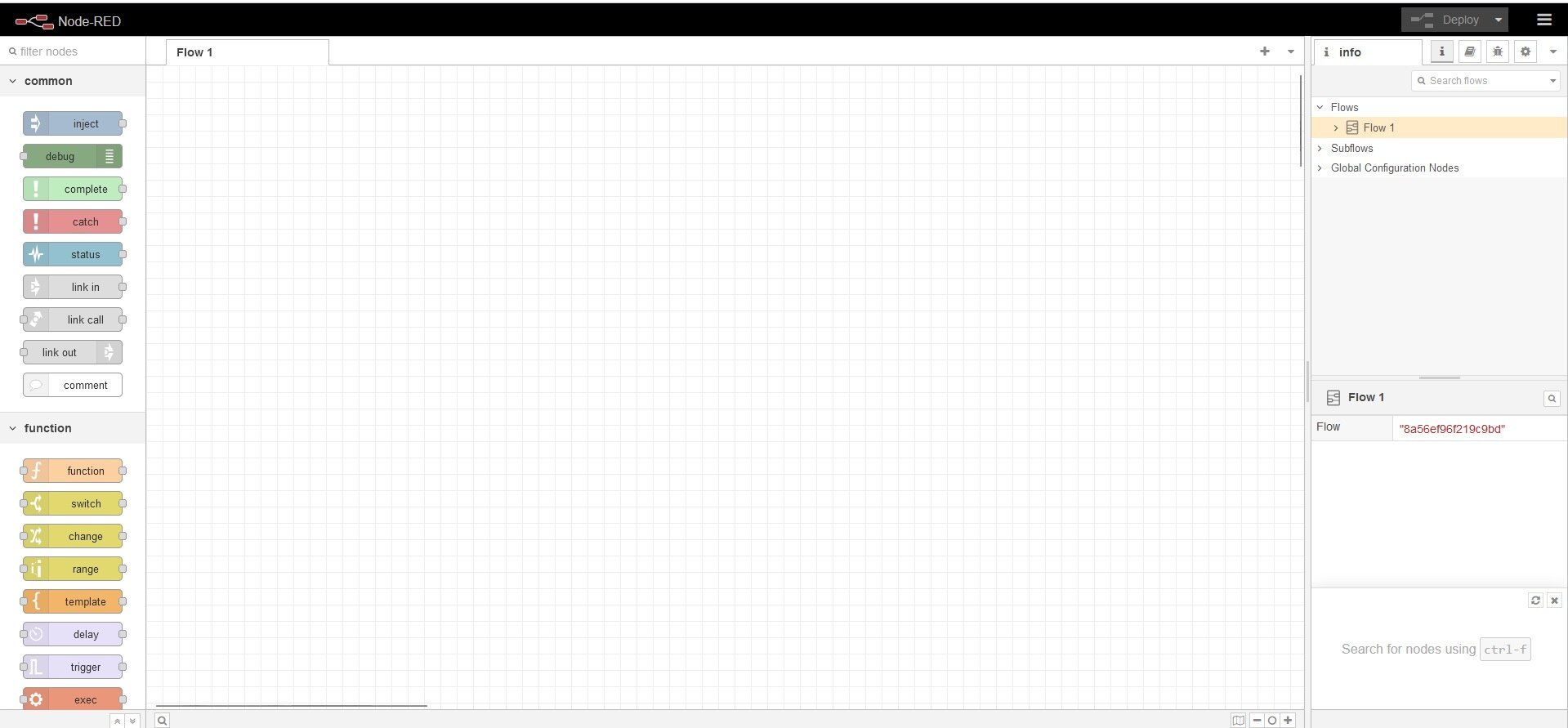
Getting started with Node-RED
Great we have got the Node-RED up and running. Now let's get start with a very simple example before going to our main project. As we already discussed, the program we create using Node-RED is called flow and we wire multiple nodes together to create a flow. There are three main types of nodes:
- Input Nodes (e.g. inject)
- Processing Nodes (e.g. function)
- Output Nodes (e.g. debug)
Three example nodes are shown below:
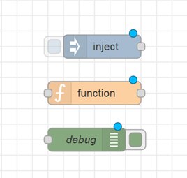
Input nodes allow you to input data into a Node-RED program or flow. They have at least one output endpoint represented by small grey square on their right side. Output nodes are used to send data outside and have a single endpoint on their right side. Processing nodes allow us to process data. They have an input endpoint and one or more output endpoints. In a Node-RED flow messages pass between nodes, moving from input nodes through processing nodes to output nodes.
Let's build a 'Hello World' flow and you will see how simple it is to use the Node-RED UI to build and deploy a flow. We will use an inject node to input some information into the flow, wired to a debug node to see the output from the flow as a debug message.
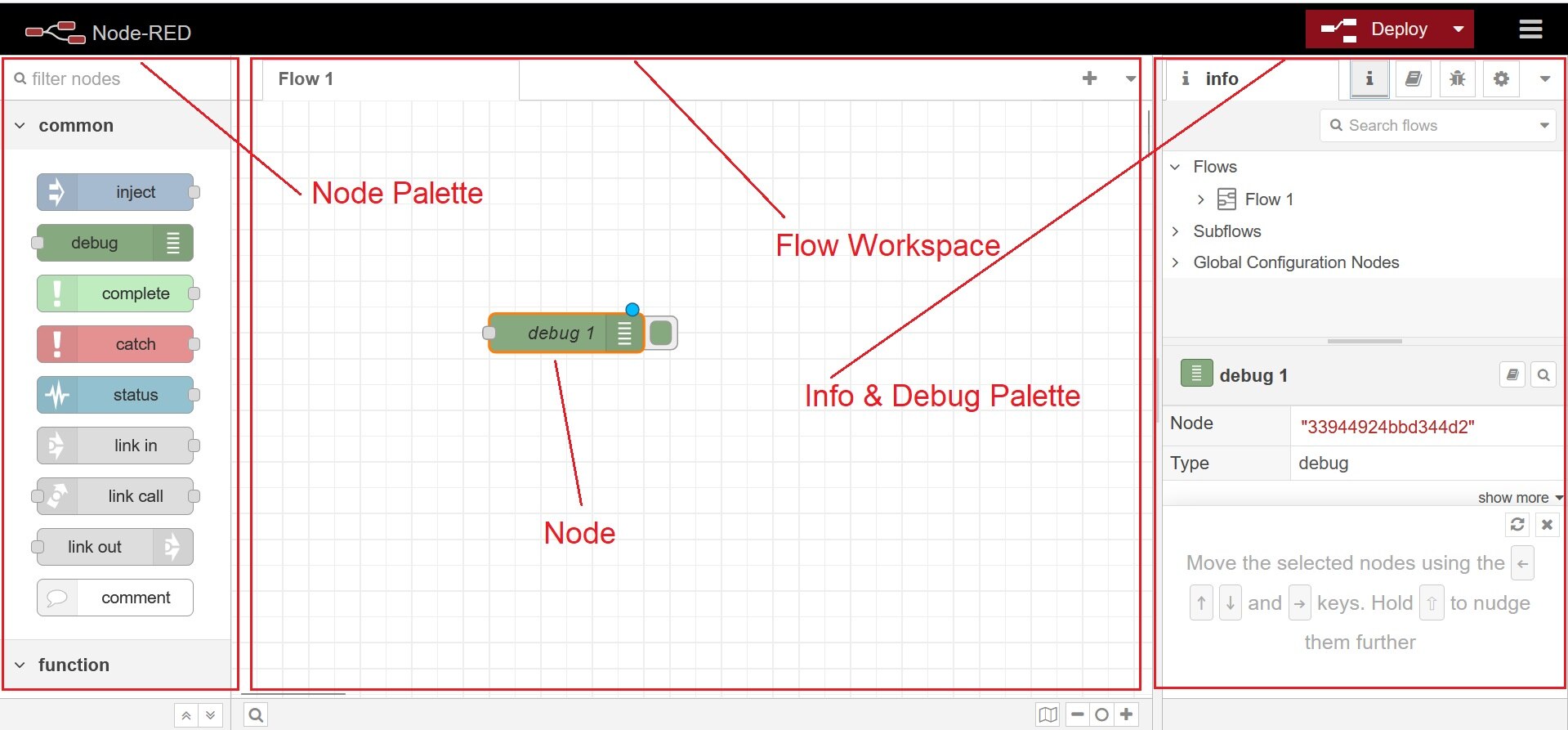
Since this is the first time we are going to build a flow, let's start slowly and explain each step with a screen-shot. Our first node will be the inject node. The inject node is used to generate input into a flow and is one of the first node in the node palette under input. Drag and drop an inject node into the flow workspace, and look at the info tab from the right, you will see the documentation for the node. Figure below shows the node palatte, workspace with added inject node and debug palatte. In the workspace inject node will be seen as timestamp as by default it inject a timestamp - the current time in milliseconds since January 1, 1970.
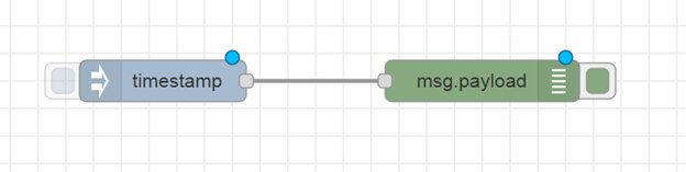
You will see a grey square right where we will attach wires that route output message to next node in the flow. To get sense the output from the inject node let's add a debug node by dragging from node palette to workspace. There are two nodes in the workspace and we need to wire these together. To do that, click on the grey output point for the inject node, holding the mouse button down, drag towards the debug node. An orange wire appears, which you can then attach to the grey input point on the debug node. The complete flow will look like figure below.
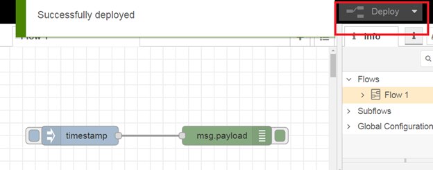
After completing the Hello World flow now we need to deploy the flow to see the output. Click the deploy button from the top right and you will see a pop-up saying the flow has been successfully deployed (see below).
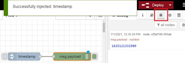
Now click on the left tab on the inject node and you will see the timestamp in the debug pane which is on the right side (see figure below).
Congratulation, you created and deployed your first flow. We are ready to move on to the next step.
Our goal is to receive multimeter reading from Raspberry Pi using MQTT communication protocol and display the data to a graphical web dashboard. Node-RED will be used to receive MQTT data, make a graphical dashboard to display the result in real-time. So, let's start step by step.
Receiving MQTT message in Node-RED
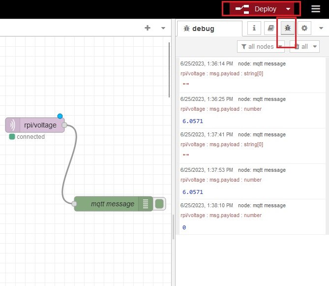
To receive the mqtt message first, drag and drop an 'mqtt in' node and configure it for the mqtt broker. To configure double click on the node after dropping it into the workspace. Enter your topic in the topic field (e.g./# - for receiving all the messages, (taifur/home/data- for voltage). I set the topic to receive the voltage here as shown below to observe the MQTT data sent from W5300 TOE Shield.
To watch the received message from the mqtt broker we need a 'debug' node. So, add a debug node and wire it with the 'mqtt in node'. Deploy the flow. You will receive all the mqtt messages in every publish as shown in image below.
Creating the Dashboard
It would be nice to have a nice UI instead of raw print out, wouldn't it? The good news is Node-RED allows to build a decent UI and we will use it to build a basic dashboard for our device to plot temperature data and show the battery status.
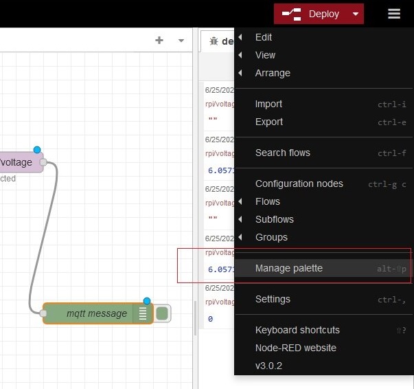
However, there is one extra component called 'node-red-dashboard', which we have to install to Node-RED. In order to do that, click on the account icon from top right and select 'Manage palette' as shown in the figure below.
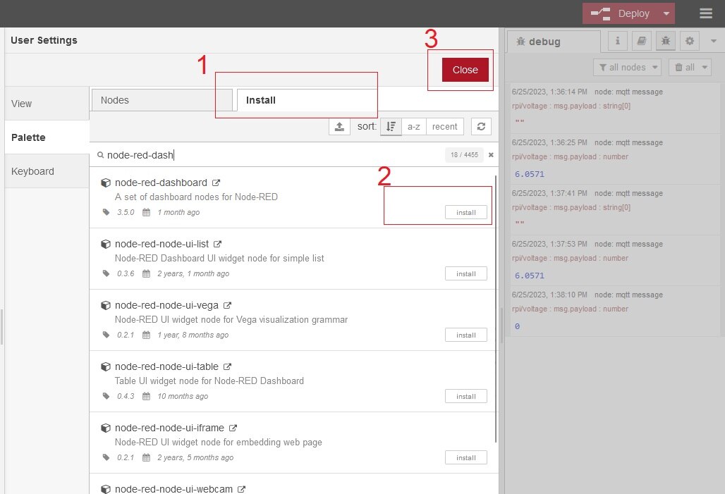
Go to the install tab, type for the 'node-red-dashboard' and click the install button as shown in the figure below. Close the window when done.
Now we are ready to create a dashboard. We already know our device and the exact topics it is sending out. We can precisely set topics for data we are interested in. We already added 'mqtt in' node and asign with the above topic.
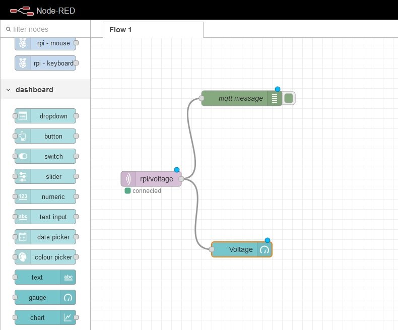
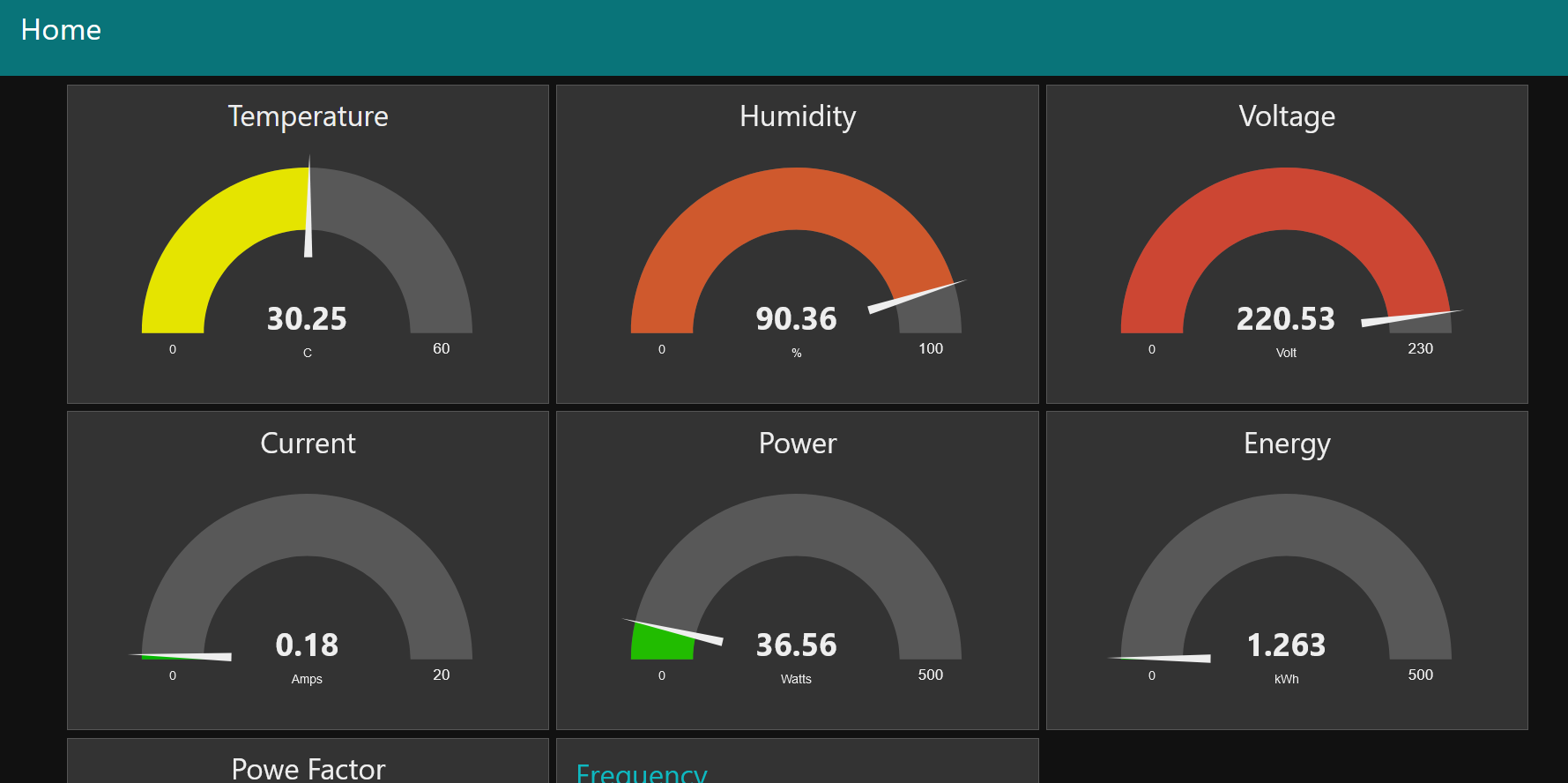
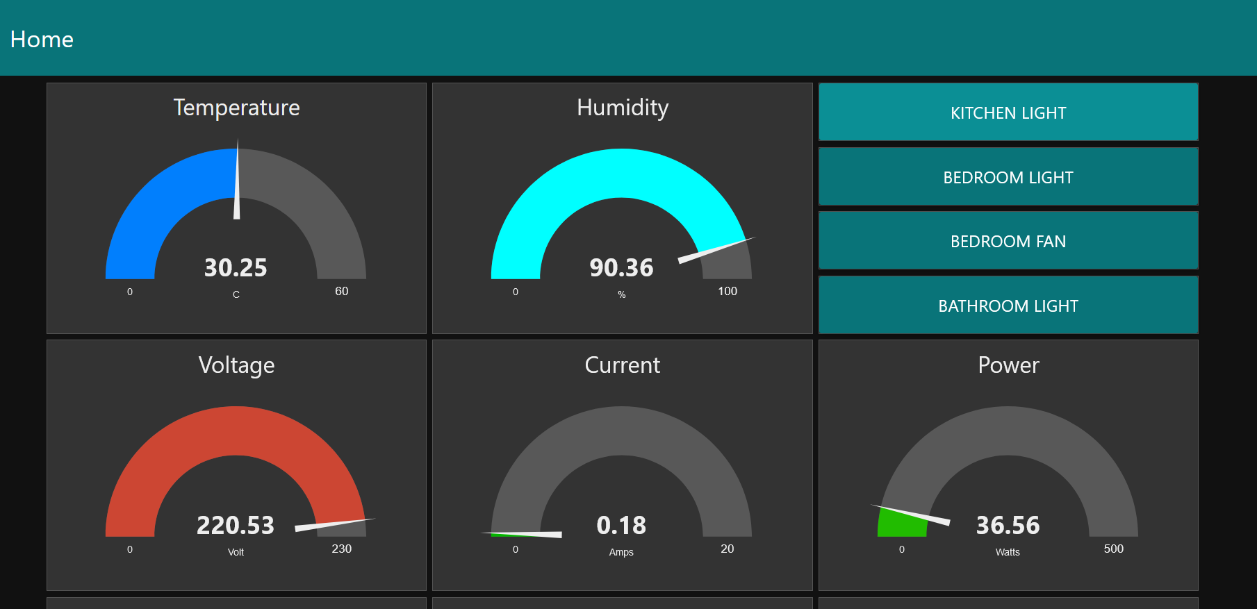
Now let's add a 'gauge' node (for battery) from the dashboard palette and connect it with the mqtt input. You need to assign a group for the gauge node. Double-click on the nodes and assign 'Home' group with 'Dashboard' Tab for the node.
Now we are ready to deploy and open our dashboard by using the same link address as we used to open Node-RED editor. We only need to add '/ui' suffix at the end of the address. In our case the link looks as follows: http://192.168.1.103:1880/ui. After going to the address you will find a nice dashboard.
The Dashboard I made for observing the data is as follows:
The project is in Hackster.io: https://www.hackster.io/taifur/w5300-powered-smart-home-hub-c66fee
The project is also available on Instructables.com: https://www.instructables.com/W5300-STM32-Based-Smart-Home-Hub/
-
Source Code in GitHub
The code was developed in STM32CubeIDE

-
Connection Diagram
Made by Photoshop

-
W5300 TOE SHIELD Schematic
Provided by WIZnet
-
Android App Source Code
Developed in kodular.io and can be modified in both kodular and app inventor.
-
Hardware architecture & software model
-
Read it in Hackster
-
Read it in Instructables