
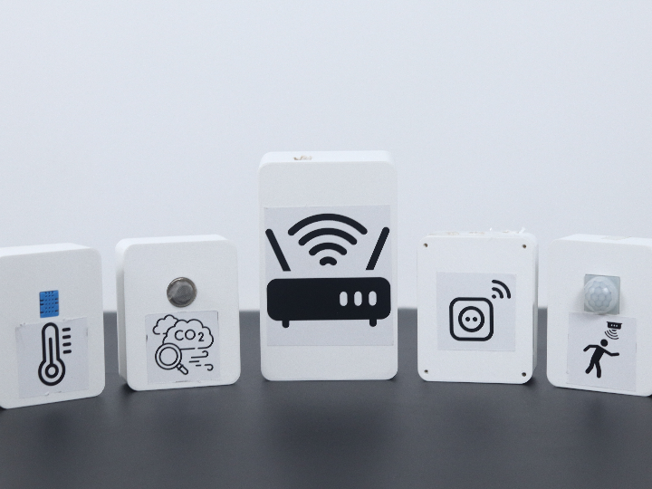
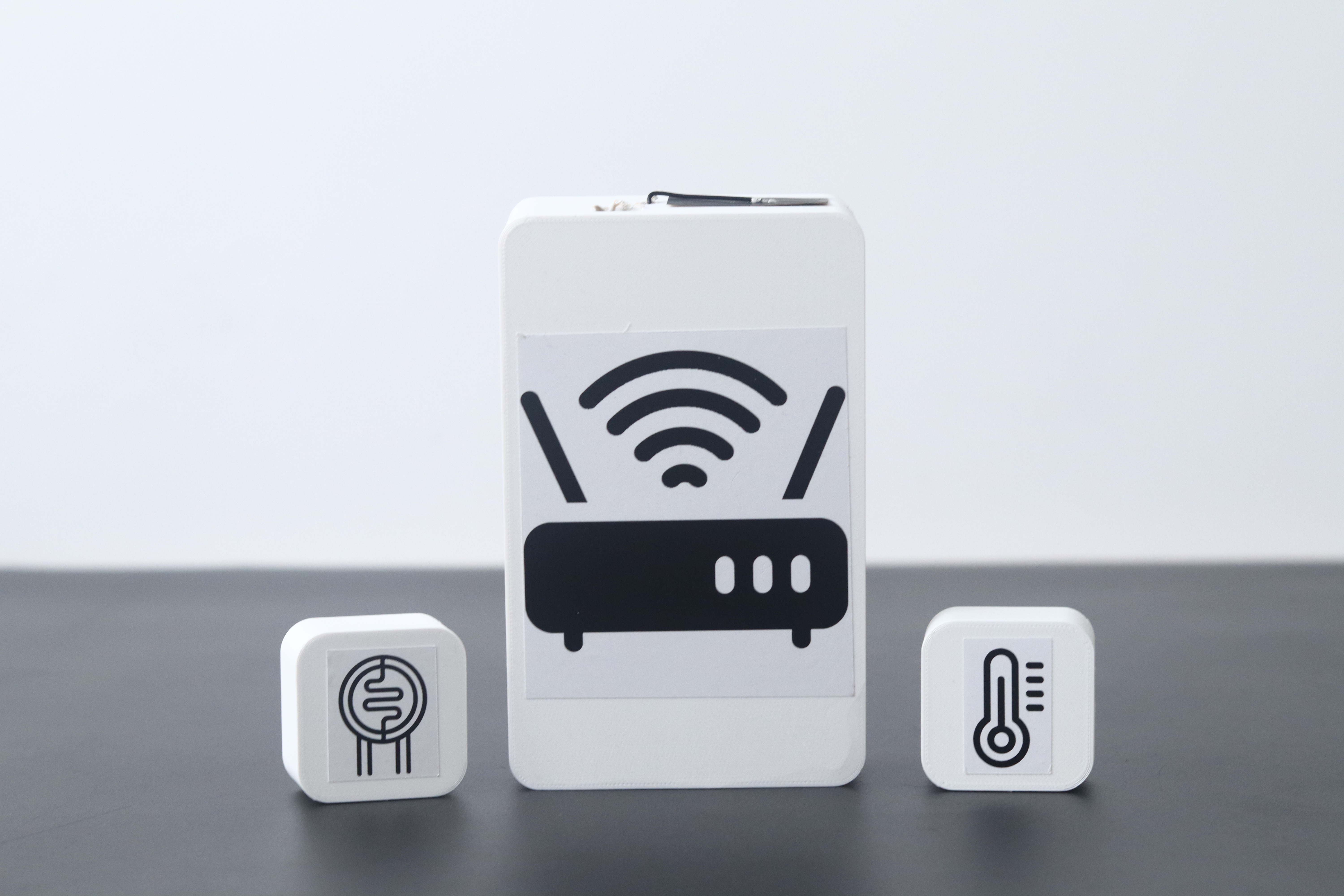
Modular IoT Kit
No Code, No Limits: Effortless Setup, Endless Possibilities With Modular IoT
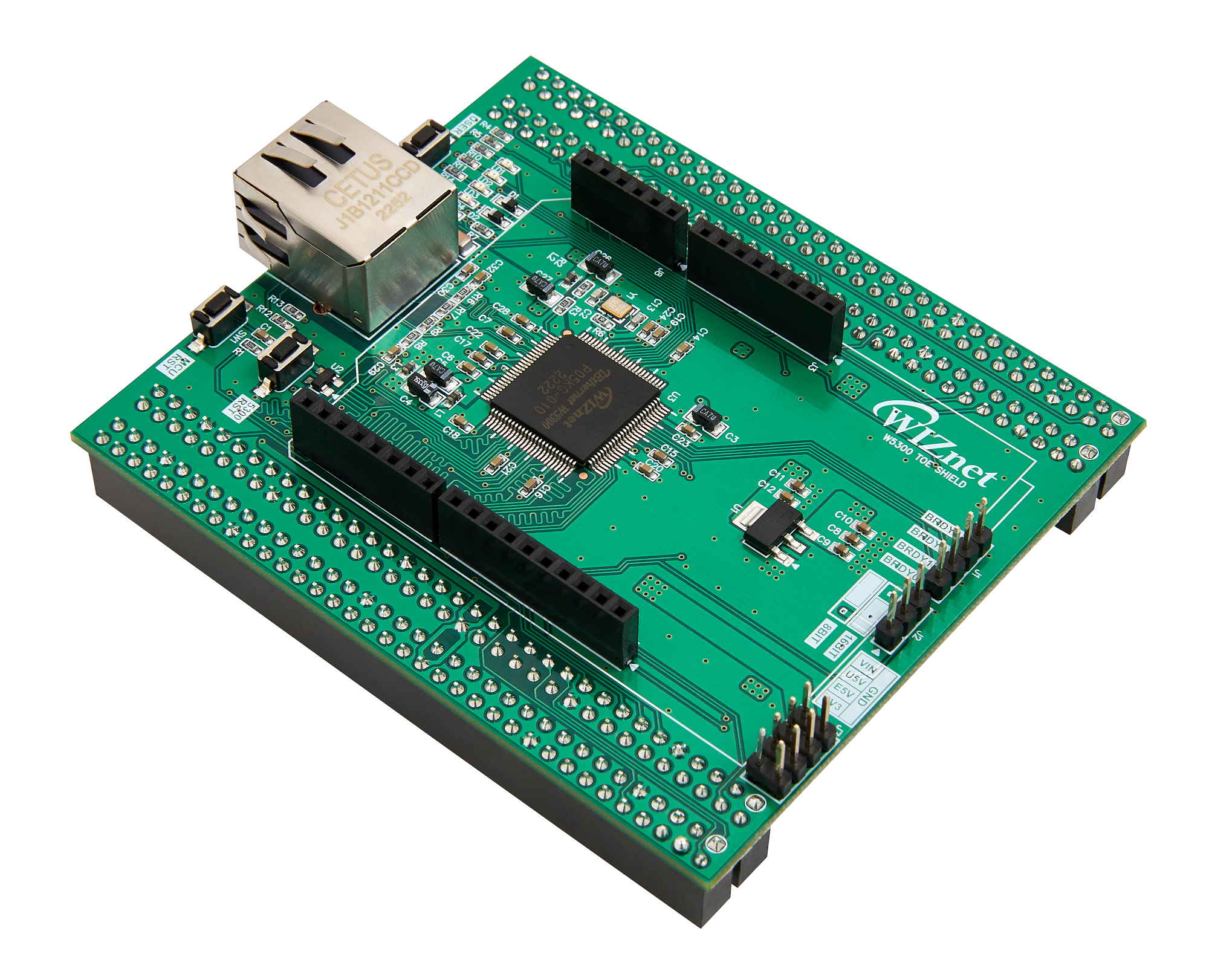
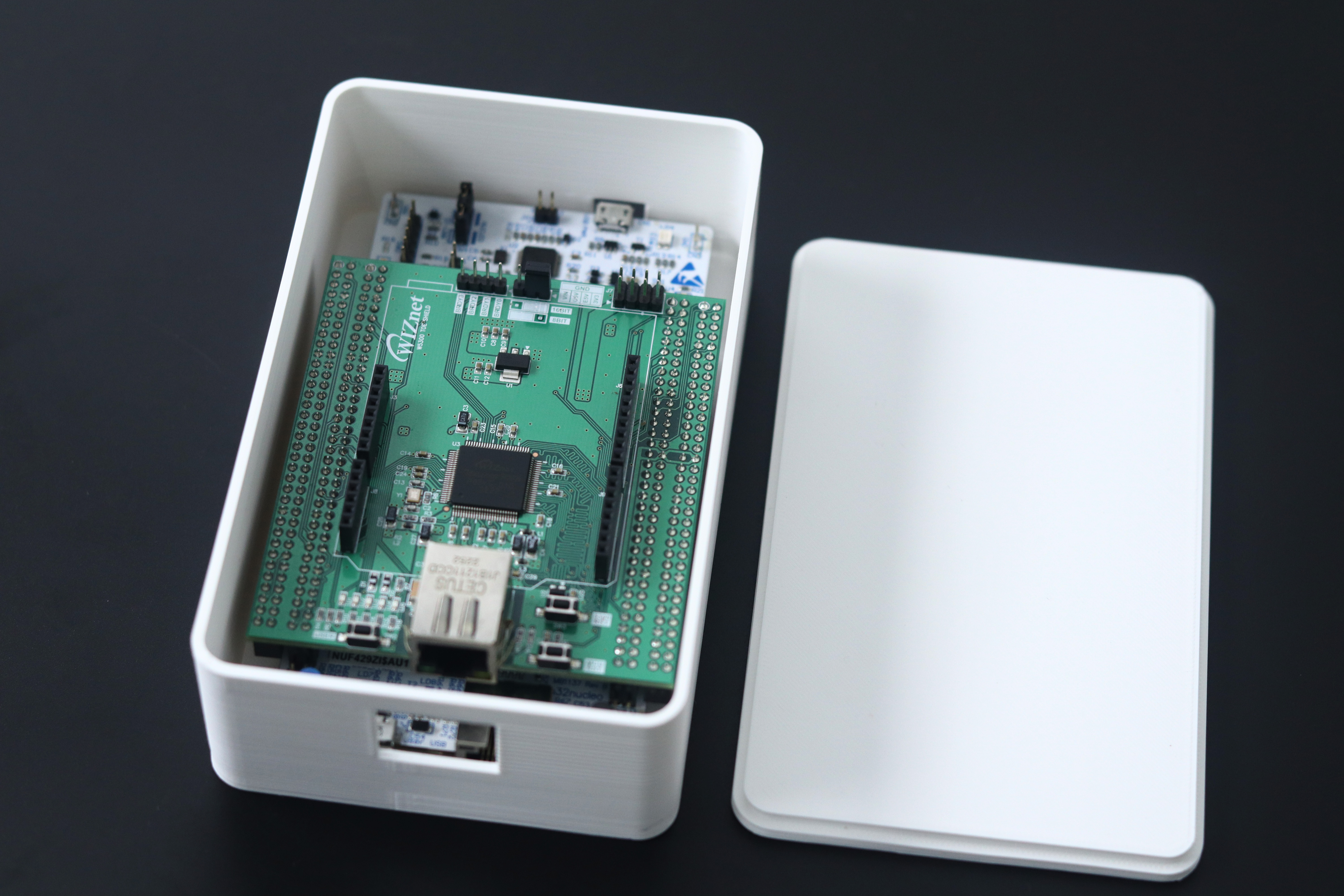
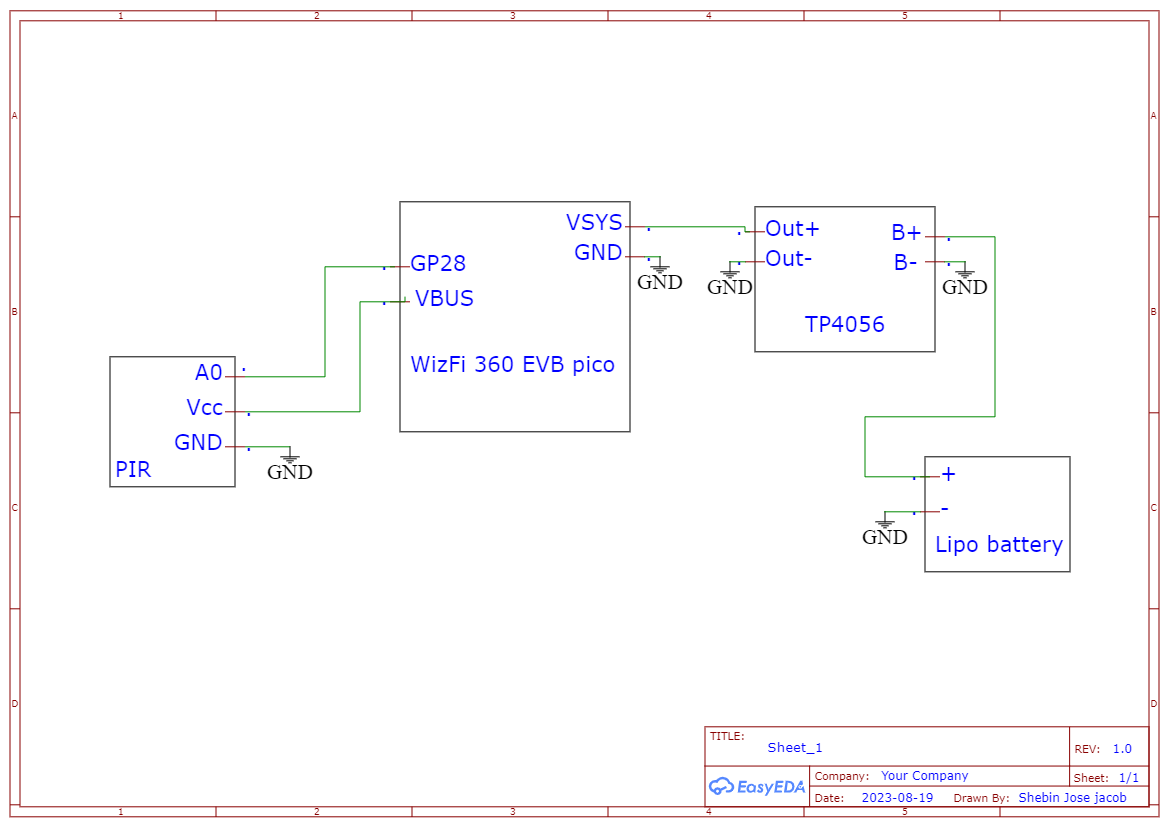
WIZnet - W5300-TOE-Shield
x 1
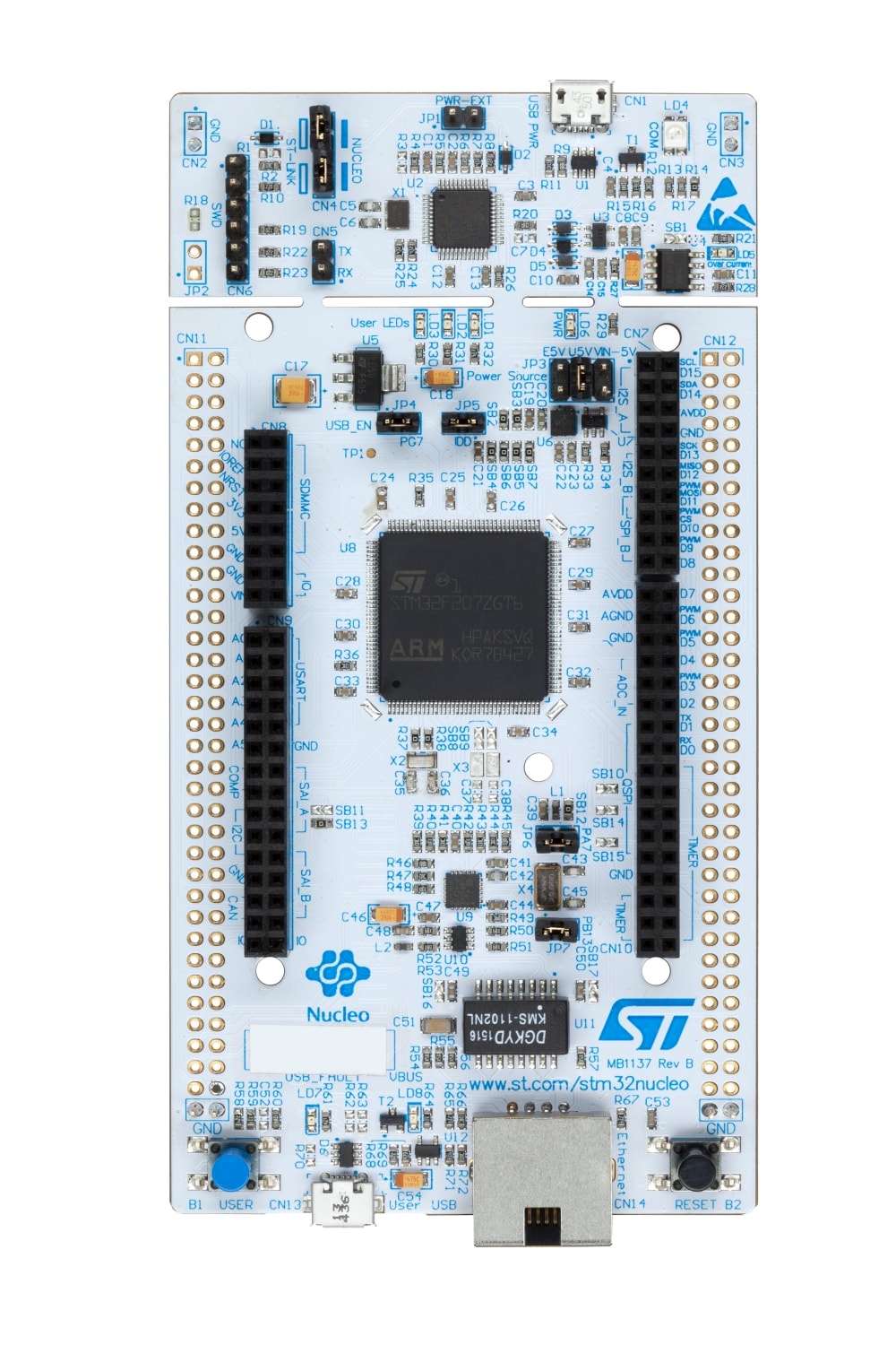
ST - NUCLEO-F429ZI
x 1
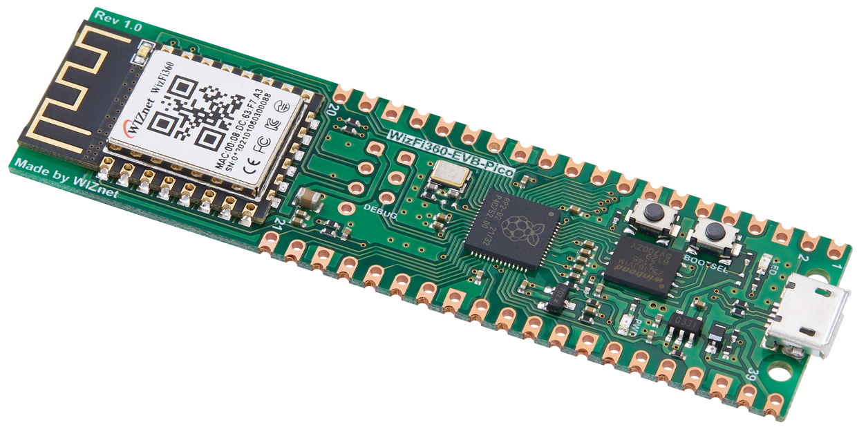
WIZnet - WizFi360-EVB-Pico
x 1

Arduino - Arduino IDE
x 1
microsoft - VS Code
x 1

Autodesk - Fusion 360
x 1
Features Of Modular IoT Kit
- Seamless Setup with Zero Coding: Just unbox and create your IoT network
- Open Source; all of the assets are open-sourced, and developers are welcome to contribute
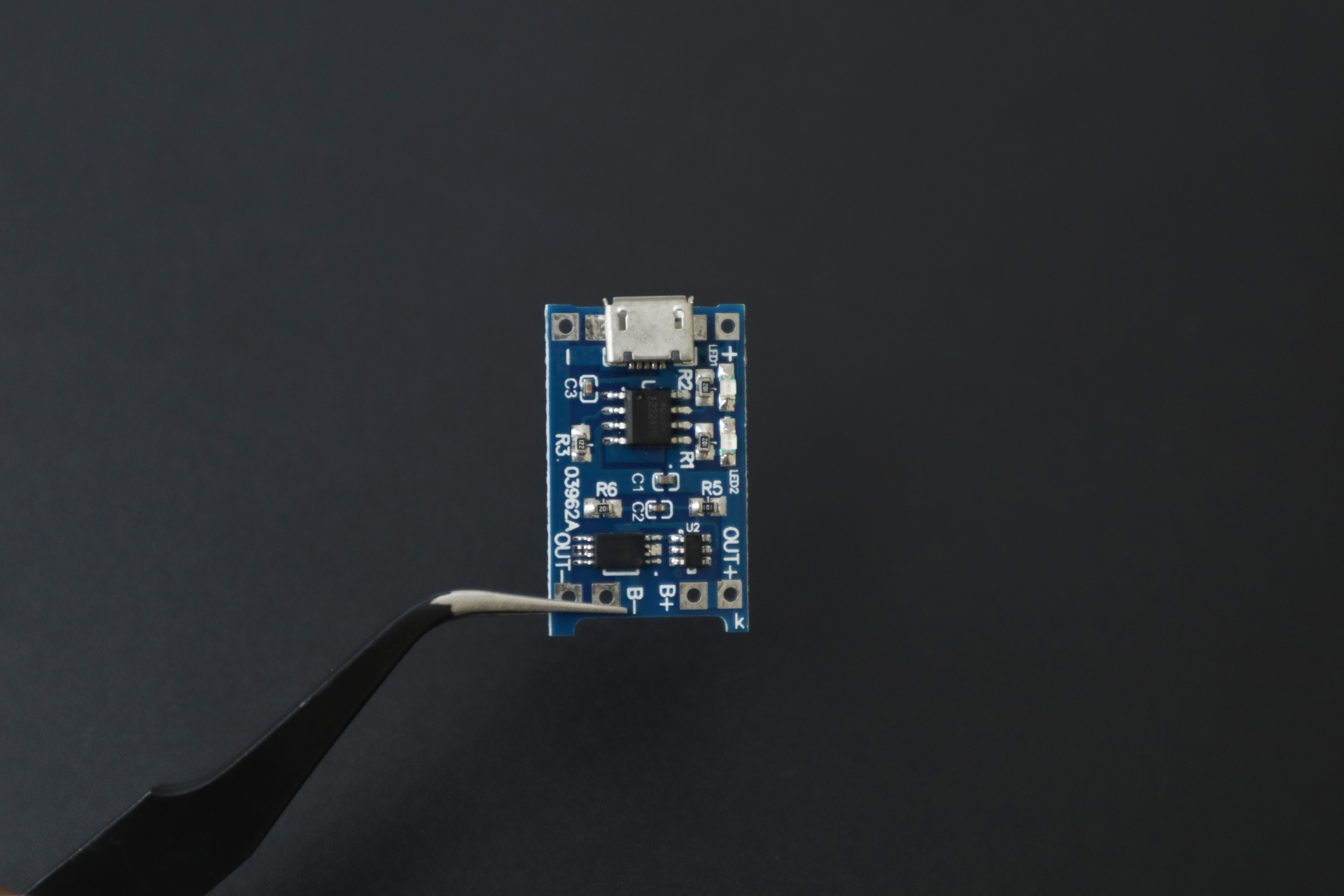
- Rechargeable Battery Powered Nodes; with self-sustaining battery power experience the freedom of placing nodes anywhere
- IoT for everyone: The kit is designed in such a way to use it for all different purposes from Smart Home to Smart Industries.
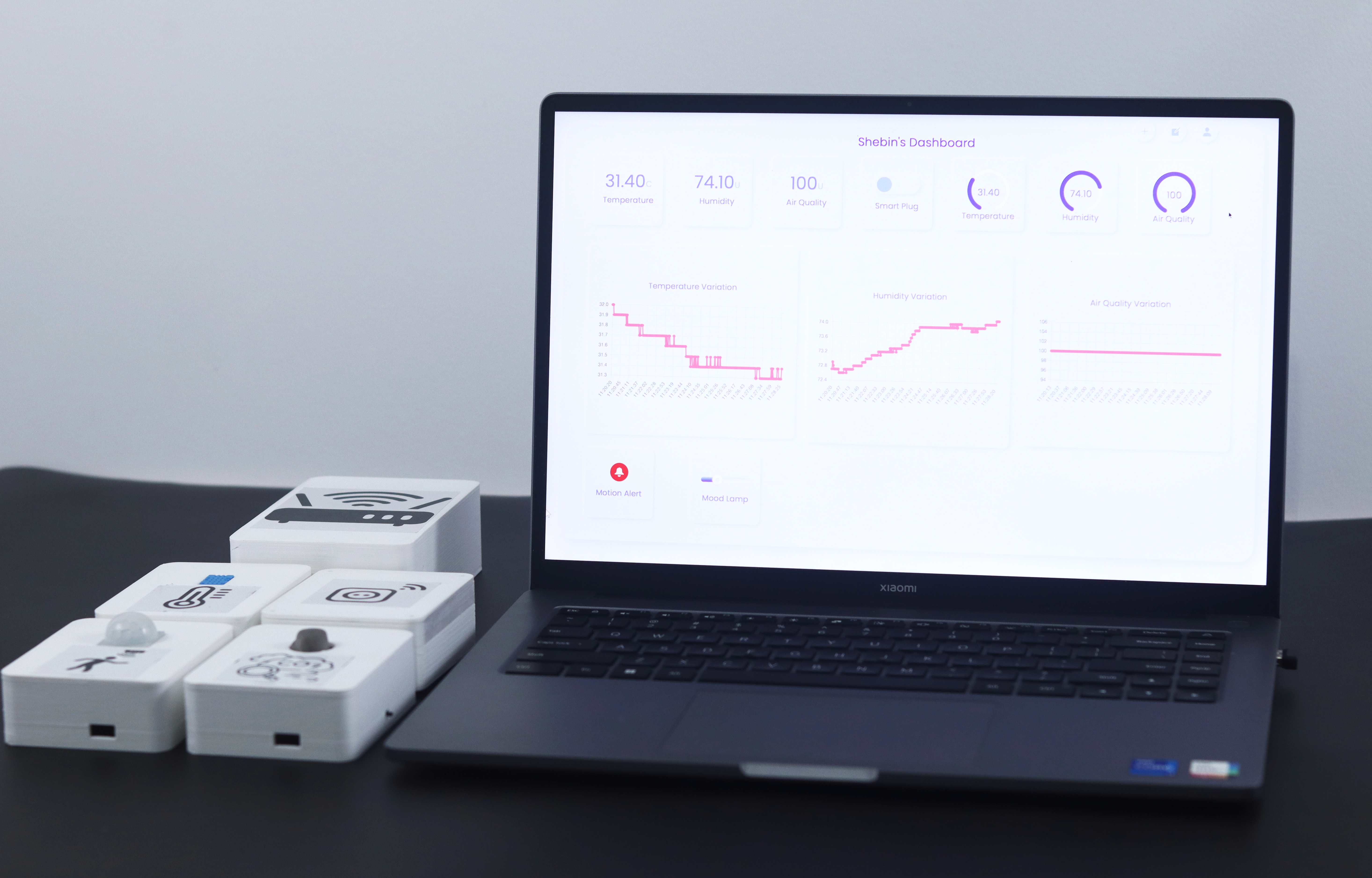
Setting Up IoT Network With Modular IoT Kit: Users' Guide
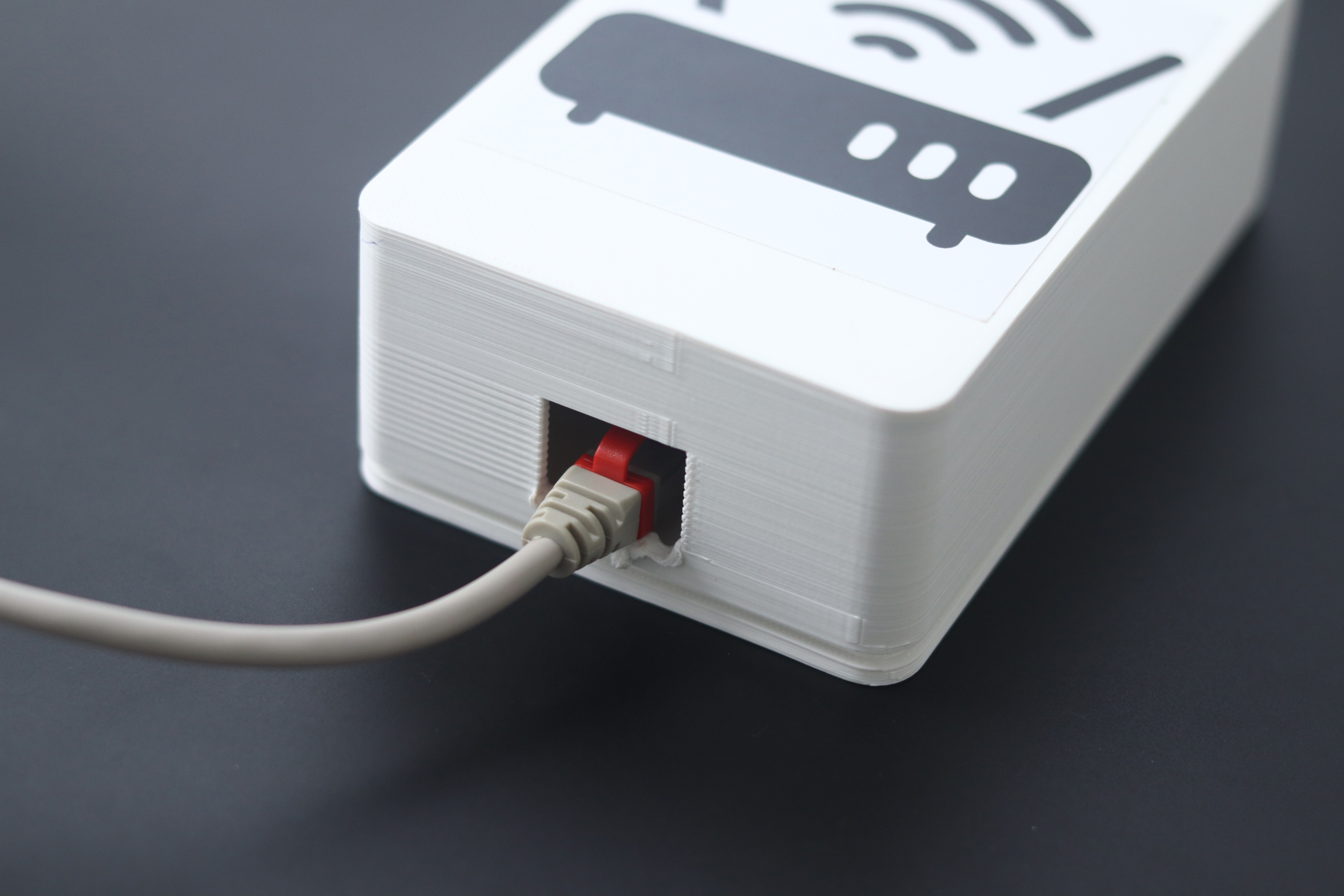
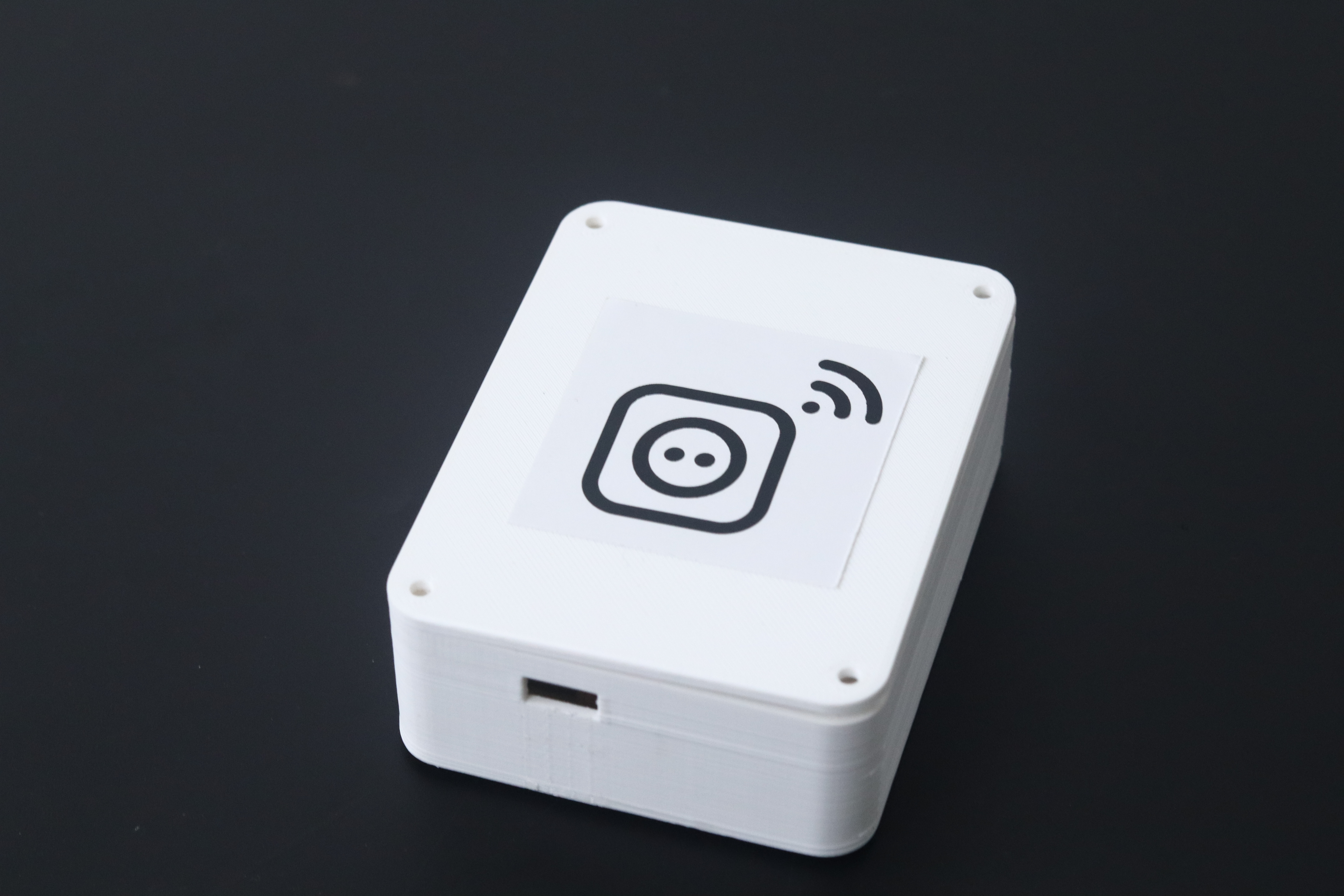
Setting Up The Gateway
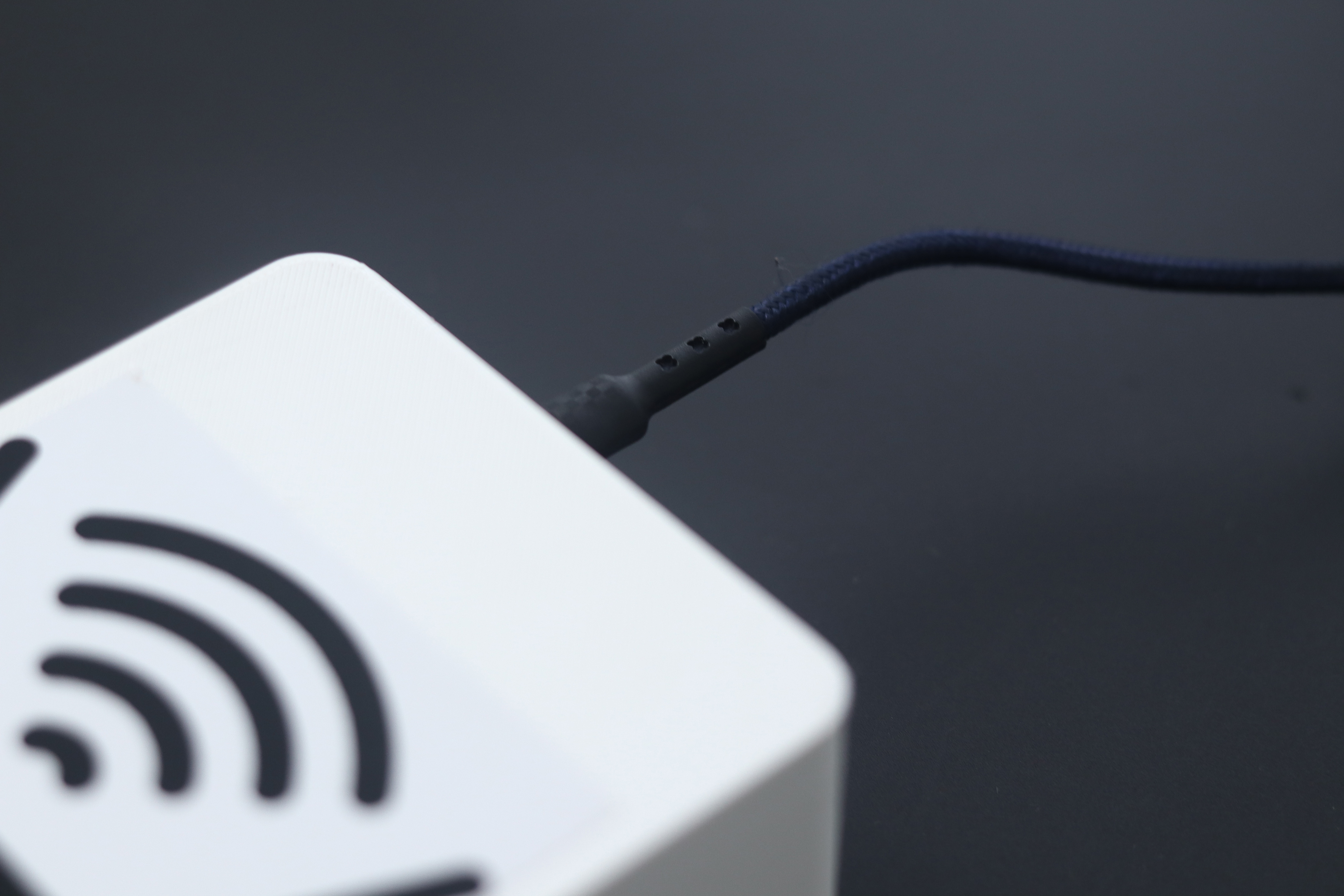
- Unboxing and Initial Setup: Begin by unboxing the Modular IoT Kit and locating the gateway. Power the gateway by connecting it to a power source using the provided USB cable.
- Connecting to the Internet: Use the included Ethernet cable to connect the gateway to your Wi-Fi router. This step establishes internet connectivity for the gateway, allowing it to communicate with other devices and the online dashboard.
Setting Up The Nodes
- Node Activation: Each node in the kit features an integrated battery and an on/off switch. Activate the node by turning on the switch, initiating the provisioning process.
- Connecting to the Node's Access Point: Once the node is powered on, it will create an Access Point (AP) named "wiznet". Connect your smartphone to this AP.
- Accessing the Configuration Page: Open a web browser on your smartphone and navigate to "http://192.168.2.100" This will direct you to a configuration webpage for the node.
- Configuring Wi-Fi Settings: On the configuration webpage, provide the SSID and Password of your Wi-Fi network. Submit the information to complete the provisioning process for the node.
- Repeating the Process: Repeat the above steps for each node in the kit, ensuring that all nodes are connected to the designated network.
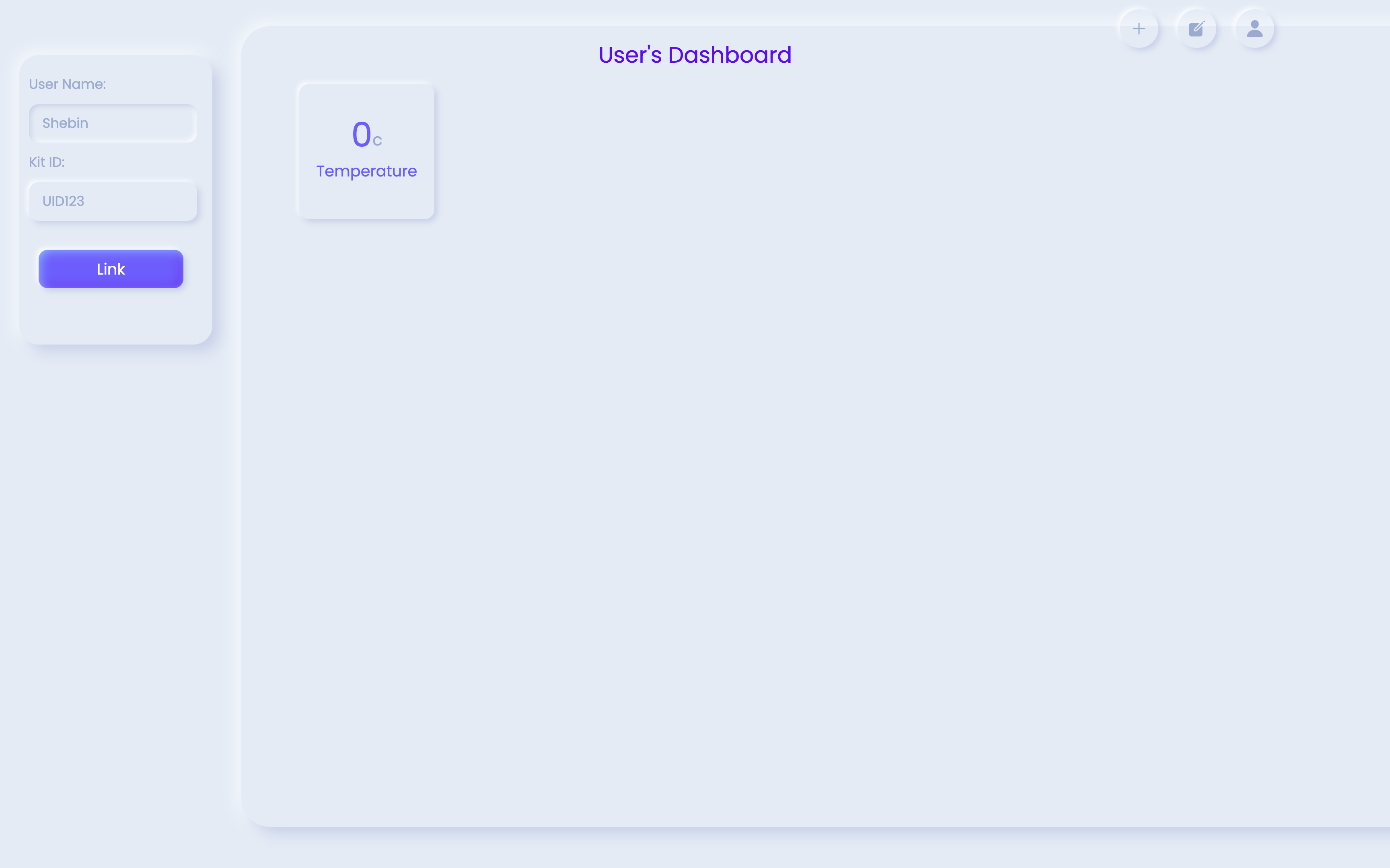
Setting Up The Dashboard
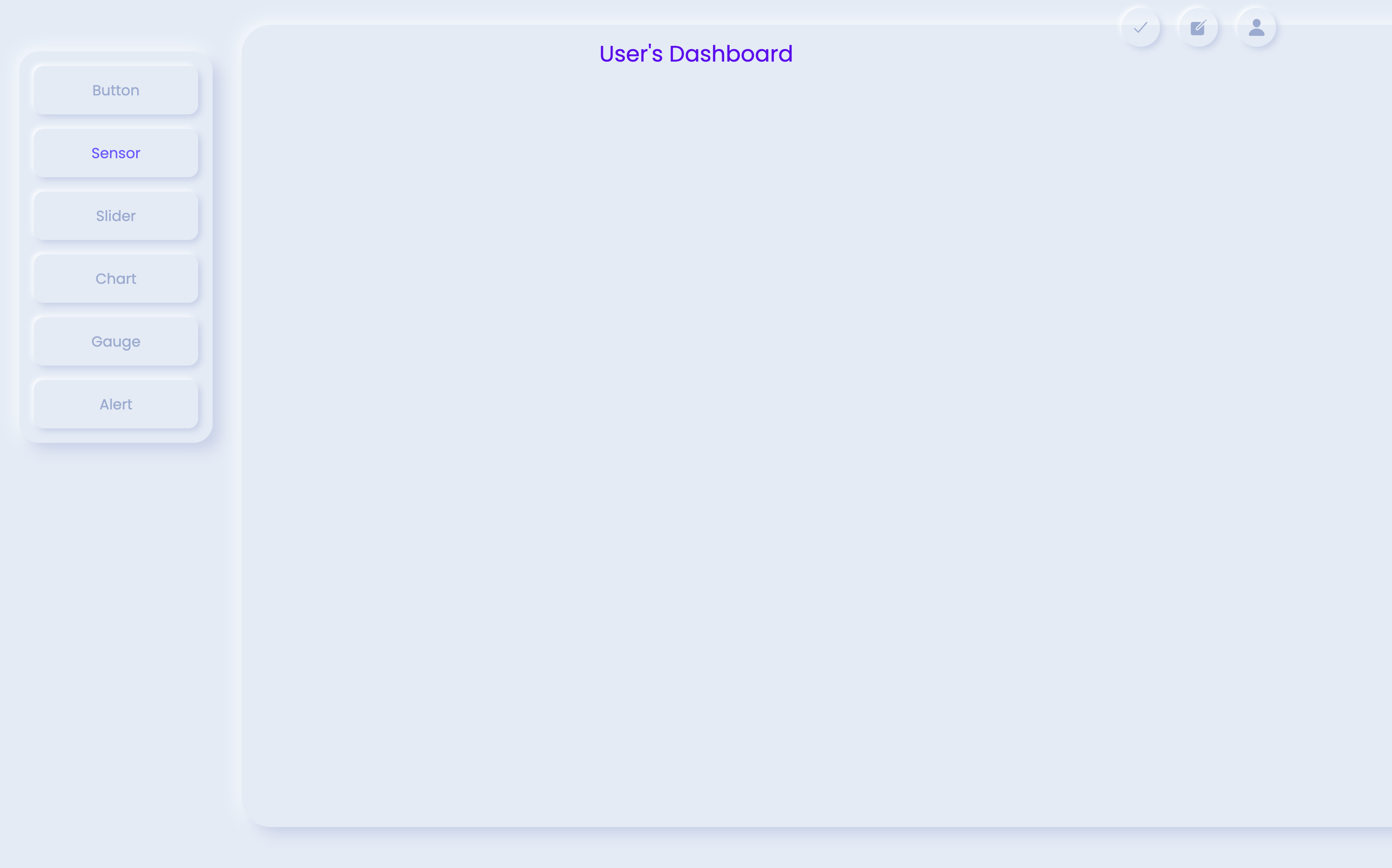
- Accessing the Modular IoT Dashboard: Open a web browser and navigate to the Modular IoT Dashboard. Upon arrival, you will see a blank dashboard interface.

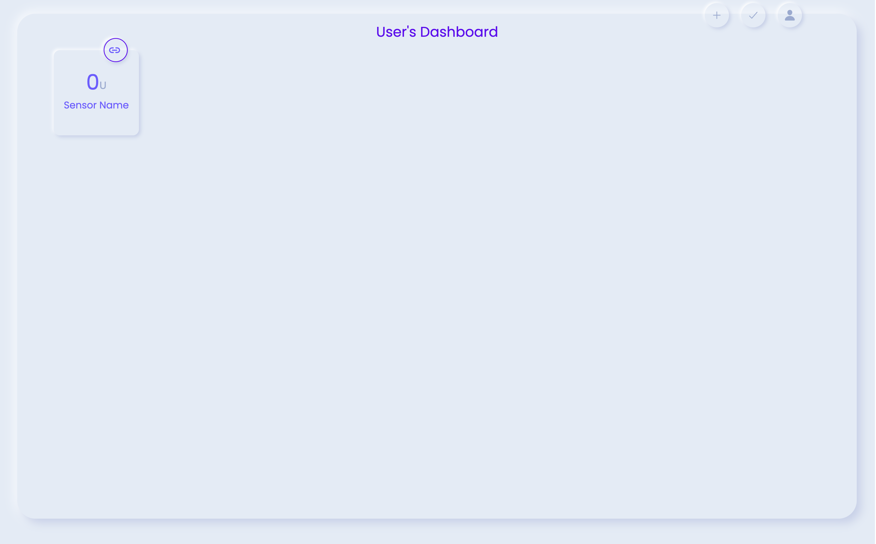
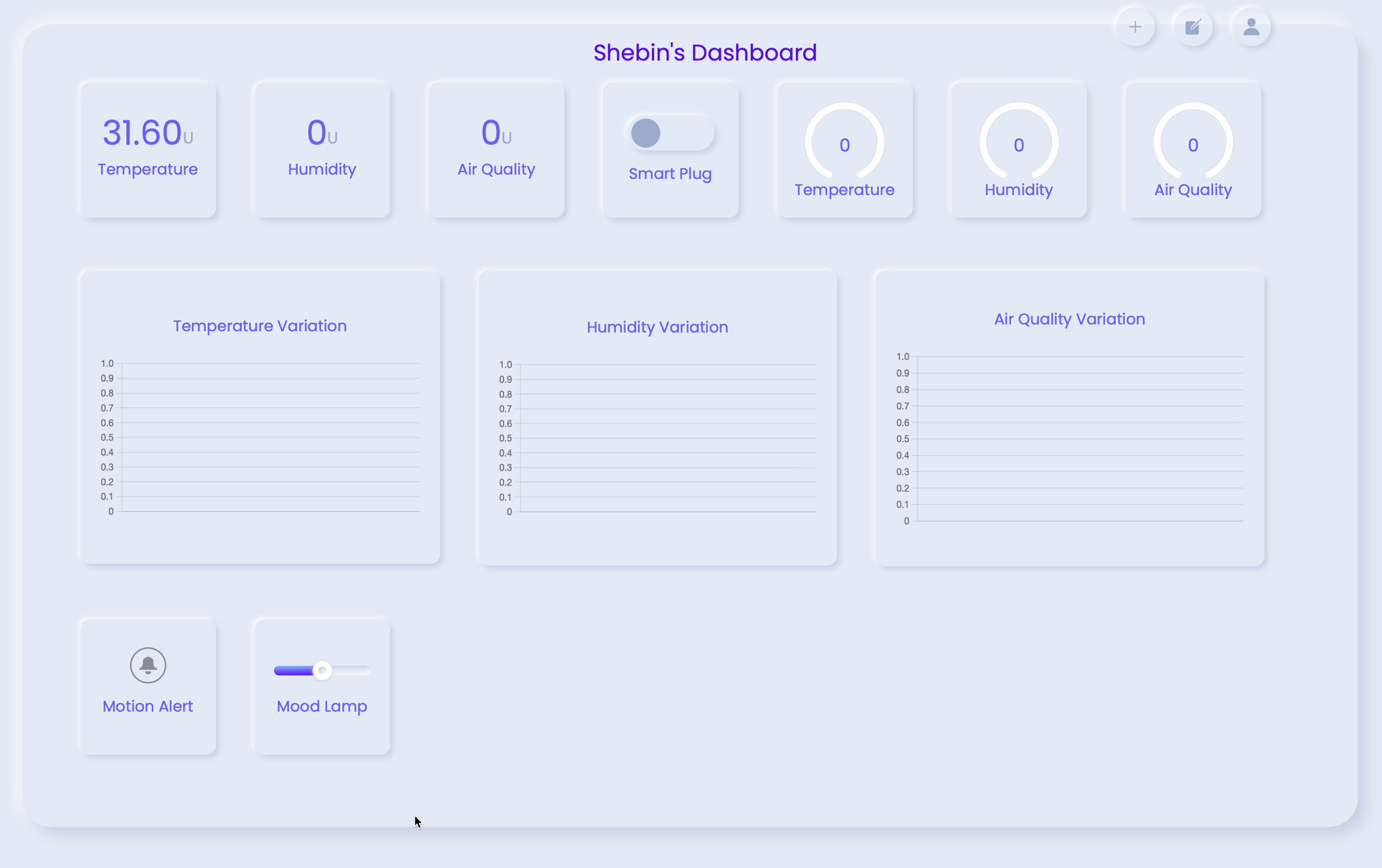
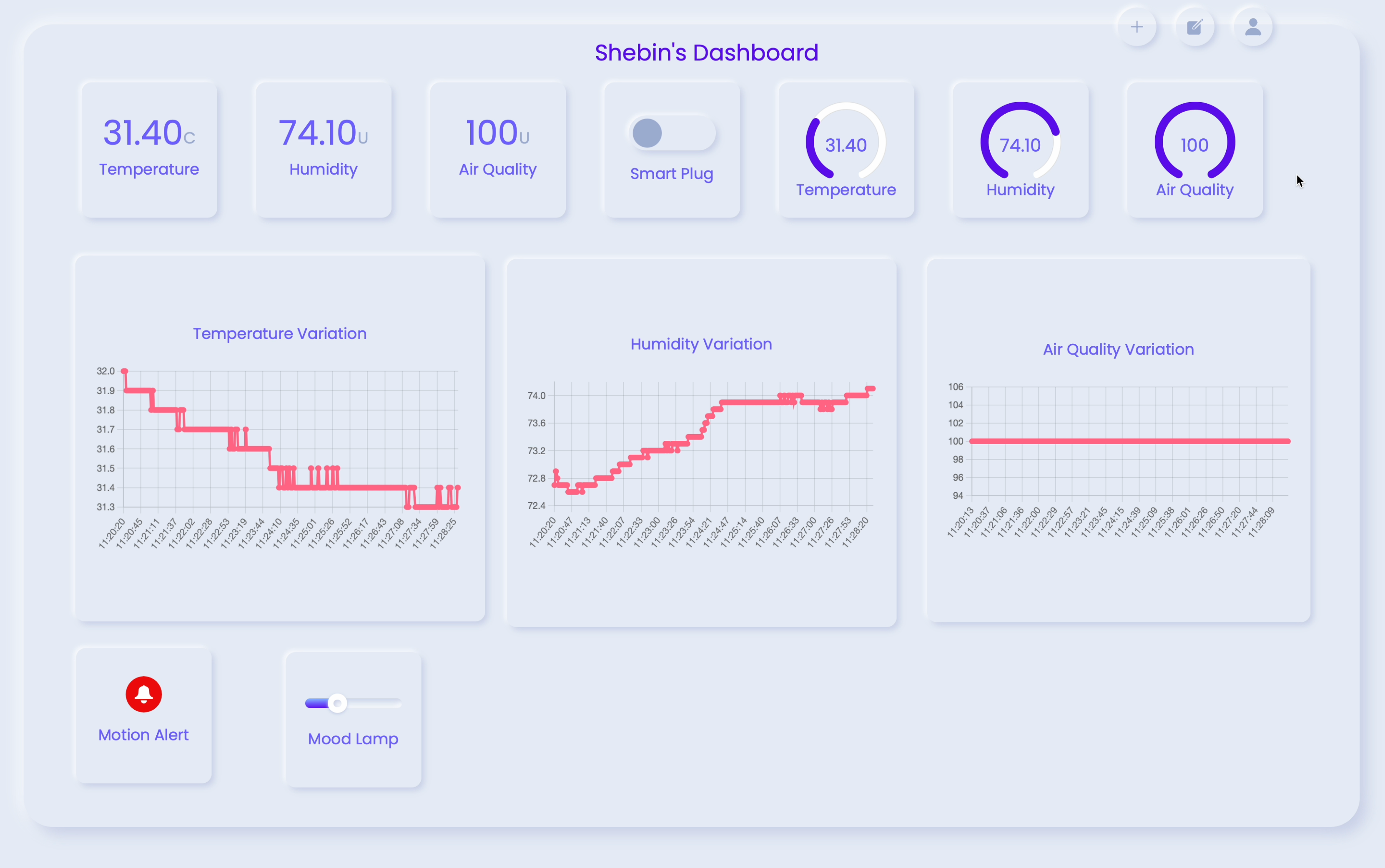
- Adding Widgets to the Dashboard: Utilize the '+' icon on the landing page to add widgets to your dashboard. Widgets are graphical elements that display data from the connected nodes.

- Customizing Widgets: The dashboard widgets are resizable and draggable, offering versatility in design. Click the edit icon to link widgets to specific nodes and configure their appearance.

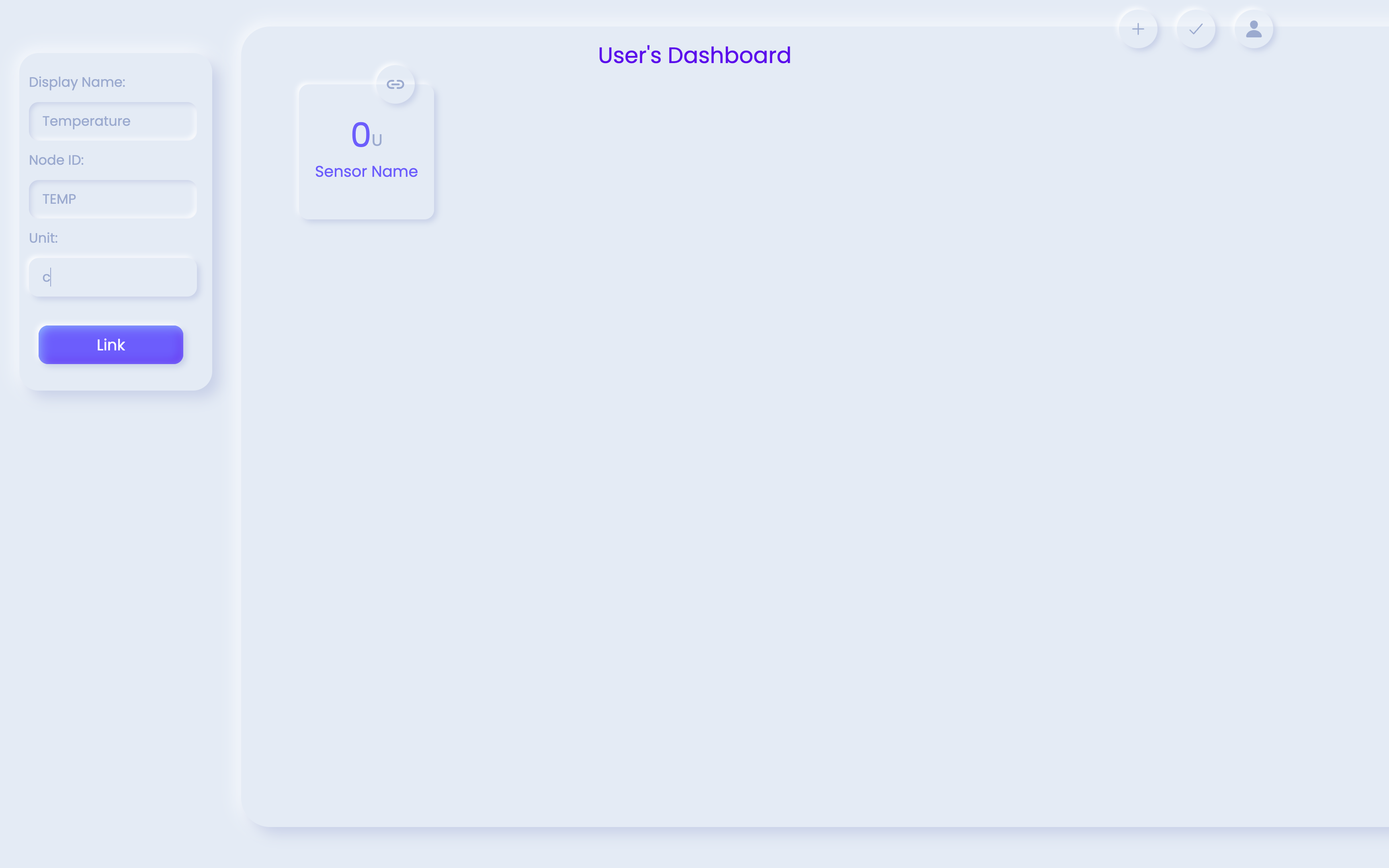
- Linking Widgets to Nodes: In the edit mode, you'll find a link icon. Click on this icon to open a form. Enter the display name and the unique Node ID for the respective node. Repeat this process for each widget, linking them to the appropriate nodes.
- Associating the Dashboard with the Kit: Click on the user icon on the dashboard to access a form. Enter your name and the unique 'Kit ID' associated with your kit. This step links your dashboard to your Modular IoT Kit.
Build Your Modular IoT Kit: Developer's Guide
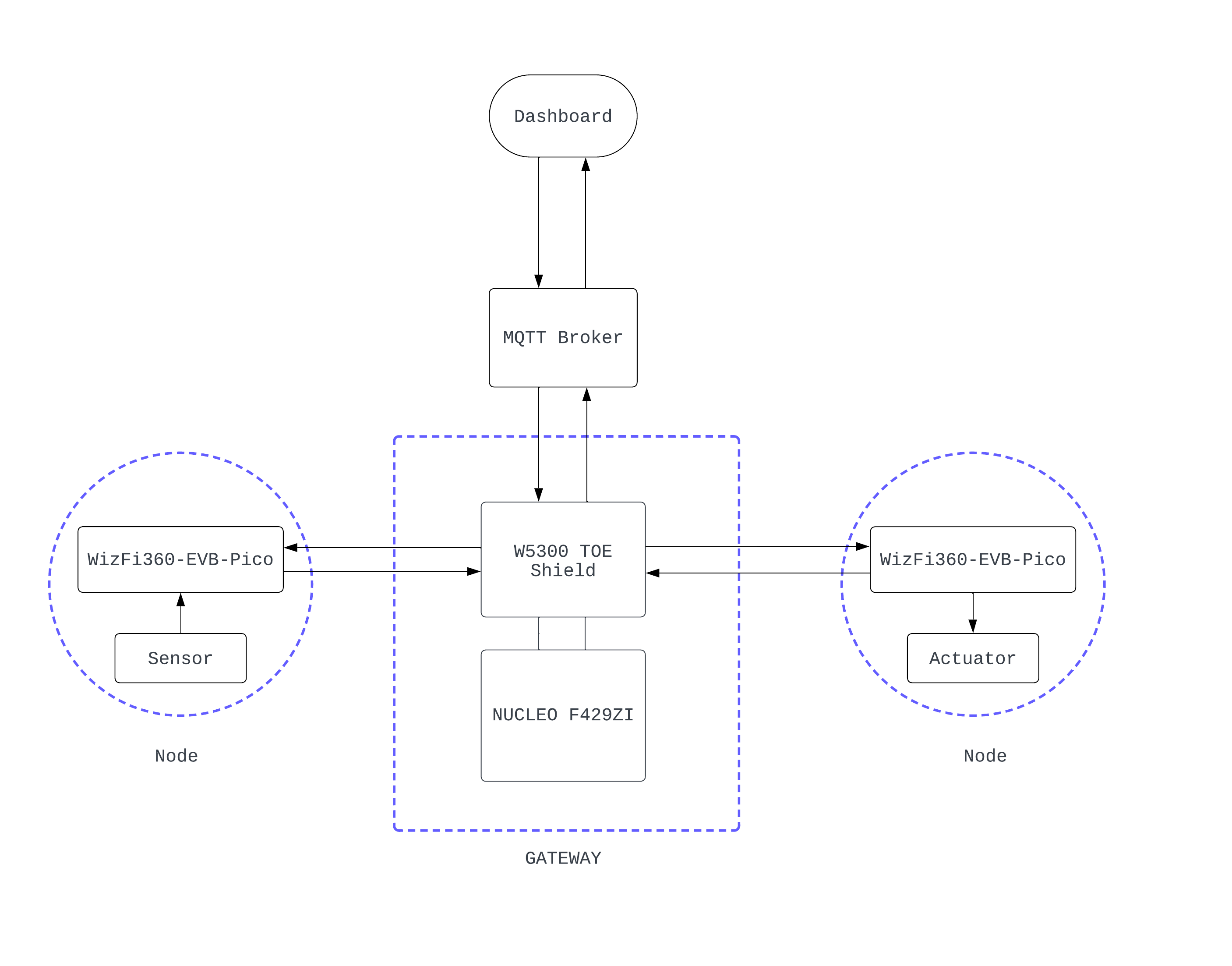
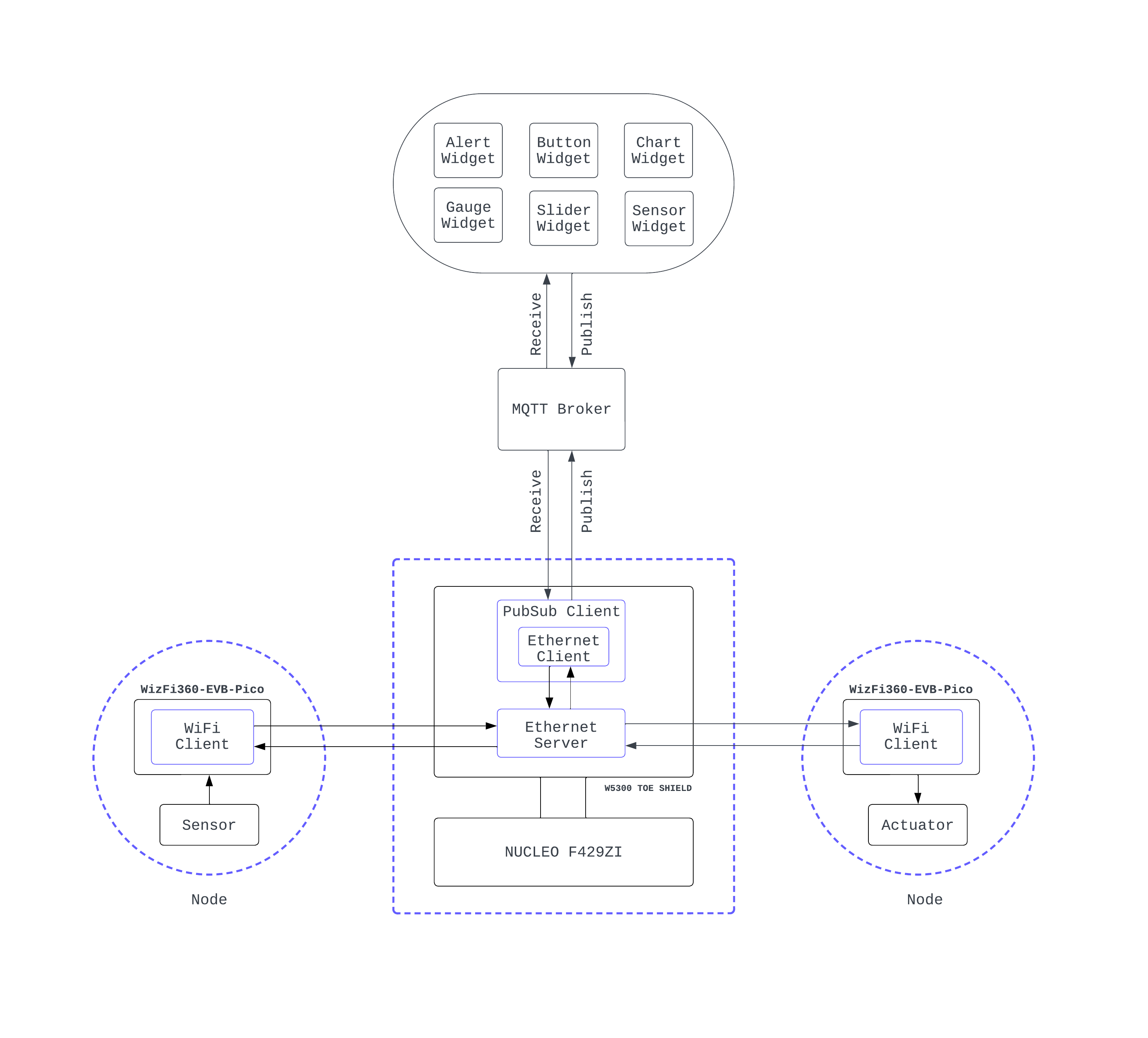
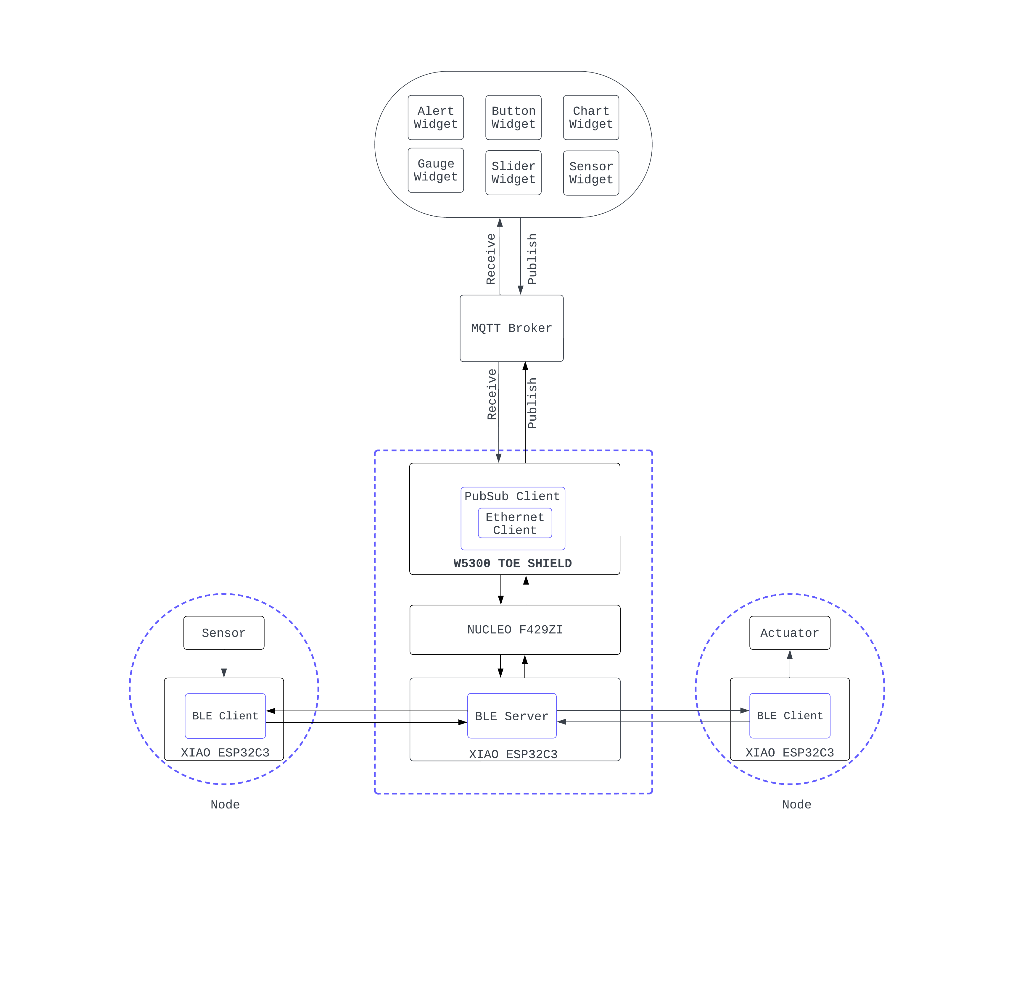
1. General Overview Of The System
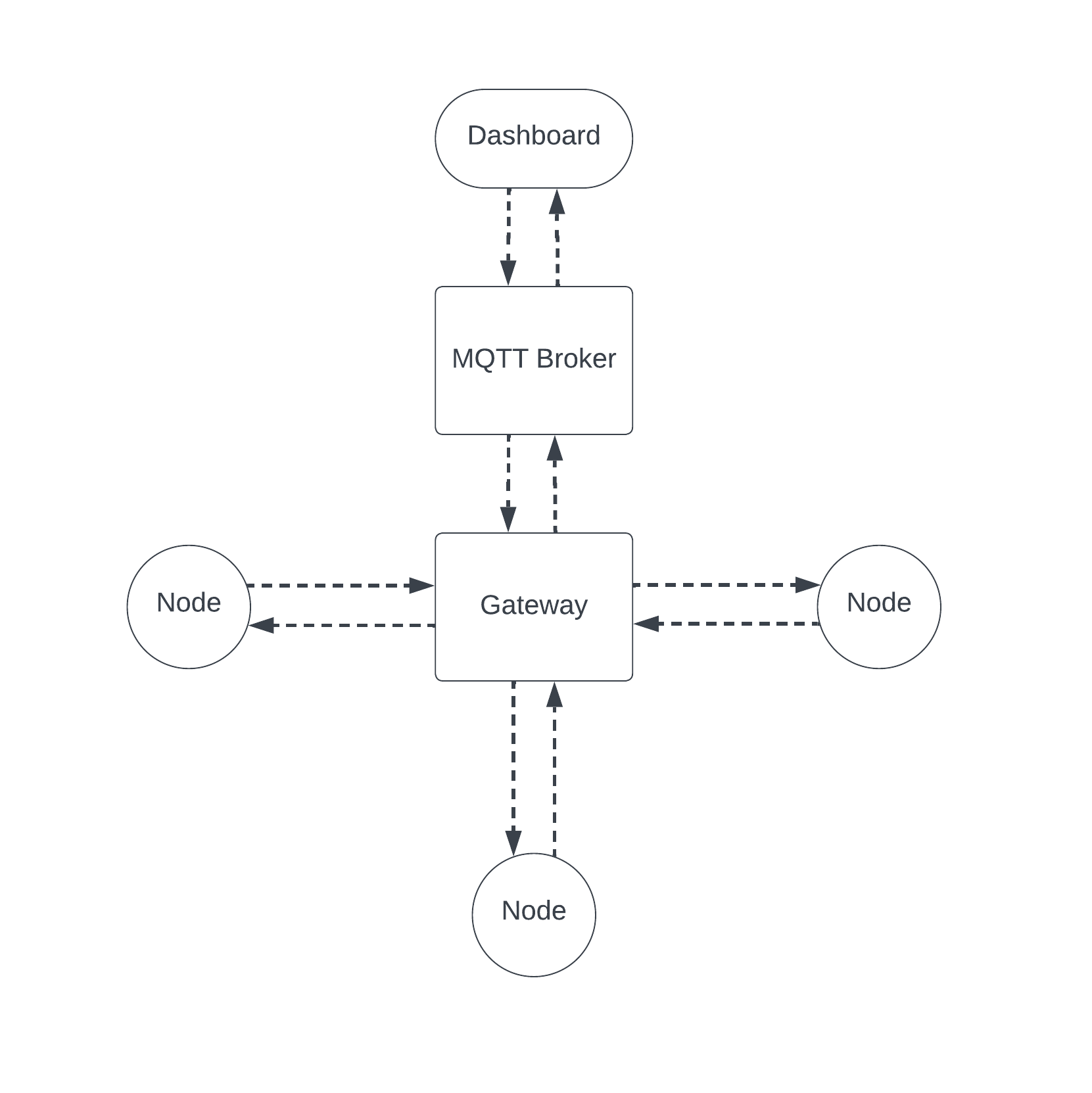
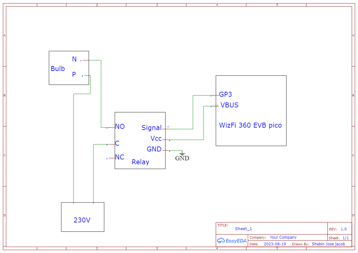
- Ethernet Server: The gateway consists of an Ethernet server, designed to accept incoming connections from nodes within the network. This server establishes a fixed address, based on the gateway's IP address. For instance, if the gateway's IP address is 192.168.1.1, the Ethernet server is located at 192.168.1.6:5000. This positioning enables efficient communication with connected nodes.
- Ethernet Client with PubSub Integration: The gateway also consists of an Ethernet client, encapsulated within a PubSubClient. This client encapsulation facilitates the transmission of data received from nodes to an MQTT broker. Data acquired from nodes is processed by the Ethernet client, then forwarded to the MQTT broker for wider dissemination.
- Sensor Nodes: Nodes equipped with sensors operate as Wi-Fi clients, actively searching for the Ethernet server on the connected network. Upon locating the server, a connection is established, and sensor data is transmitted to the server. This connection is temporary and is re-established at predetermined intervals, ensuring consistent data flow.
- Actuator Nodes: Nodes featuring actuators maintain a lifelong connection with the Ethernet server. This persistent connection enables real-time interaction with the server, facilitating immediate response to commands or instructions issued by the server.
- Data Publication and Subscription: Whenever new data is collected from the nodes, it's formatted as "nodeID: value" and published to a subscribed topic corresponding to the kit's unique identifier (Kit ID). This arrangement ensures that the dashboard receives the latest data updates from the MQTT broker
- Widget Update: The dashboard features widgets designed to display specific data. Upon receiving updated data via MQTT, the relevant widget, identified by the associated node ID, is promptly updated with the new value. This mechanism enables users to visualize real-time changes in data from the connected nodes.
2. Topology And Data Flow
Dashboard
We have developed a sophisticated yet user-friendly dashboard that serves as a powerful visualization and control hub for our IoT nodes. This dashboard represents a dynamic canvas where multiple widgets can be seamlessly added, resized, and aligned, granting users the creative freedom to compose their own intricate IoT experience.
Constructed entirely through the utilization of HTML, CSS, and JavaScript, our dashboard exemplifies a commitment to modern web technologies. The integration of the Interact JS library facilitates a seamless drag-and-drop canvas, enabling users to arrange widgets to their preferences intuitively. Moreover, the application's state is preserved using Local Storage, ensuring that the dashboard configuration remains intact even after a page reload, providing an uninterrupted experience.
A cornerstone of the dashboard's functionality lies in its ability to establish an MQTT connection between the browser and our MQTT broker. We've harnessed the power of the MQTT js library to facilitate this connection, fostering real-time data exchange and communication between the dashboard and the IoT nodes. This two-way conduit ensures that information flows seamlessly, enabling users to interact with their nodes in real-time through the familiar web browser interface.
Gateway

1. W5300 TOE Shield
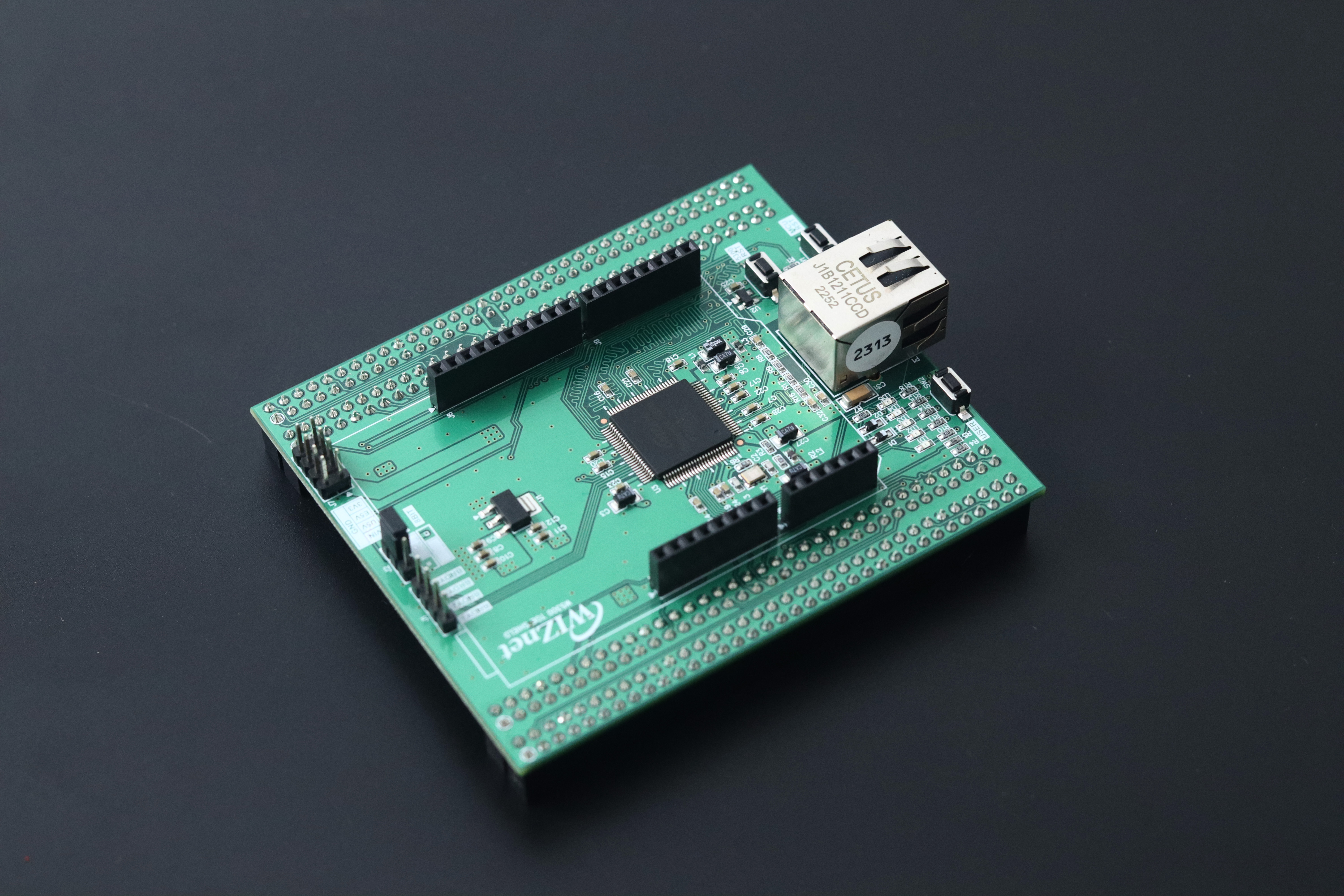 The W5300 TOE (TCP/IP Offload Engine) shield is a crucial cornerstone of gateway systems. This specialized component is pivotal in optimizing network communication processes, specifically those related to TCP/IP protocols. By offloading these intricate tasks from the main microcontroller, the shield significantly enhances network performance and responsiveness, ultimately leading to more efficient data transfers and reduced latency.
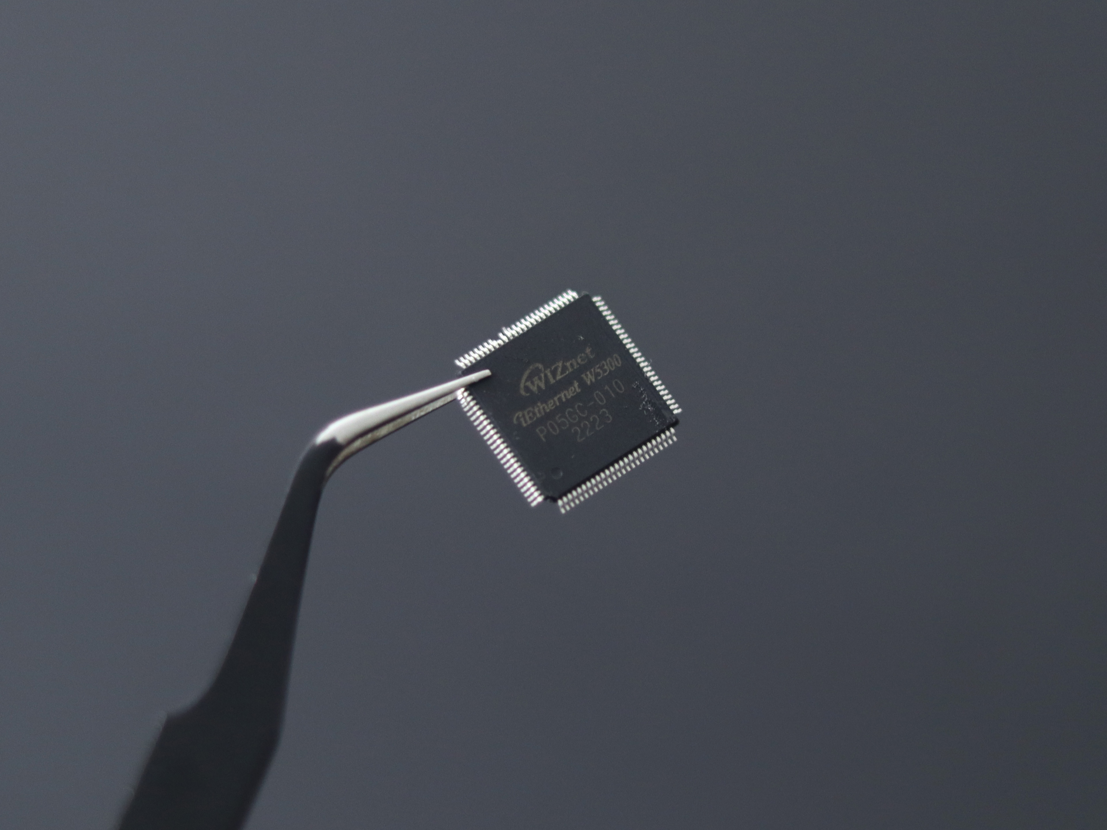
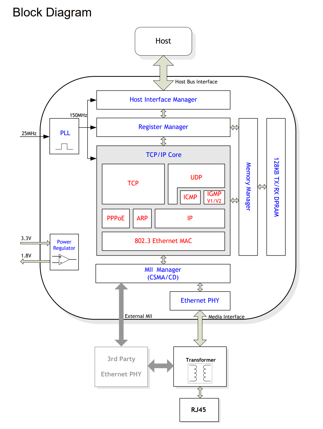
- 8 Independent Hardware Sockets: The W5300 chip provides 8 independent hardware sockets, allowing the STM32 Nucleo to establish and manage up to 8 simultaneous TCP connections. This is crucial for this project, as each client can be allocated a separate socket for communication.
- TCP/IP Offload Engine: The W5300 includes a TCP/IP Offload Engine that handles low-level networking tasks, such as segmenting data into packets, managing acknowledgments, and handling retransmissions. This offload engine ensures efficient and reliable communication between your server and clients.
- Ethernet Interface: The W5300 integrates an Ethernet MAC (Media Access Control) interface, which allows the STM32 Nucleo to connect to an Ethernet network. The Ethernet interface handles the physical layer communication, including the encoding and decoding of data onto the network medium.
- Memory Management: The W5300 features internal memory buffers that store incoming and outgoing data. These buffers temporarily hold data as it's being transmitted or received. Efficient memory management is essential for smooth communication.
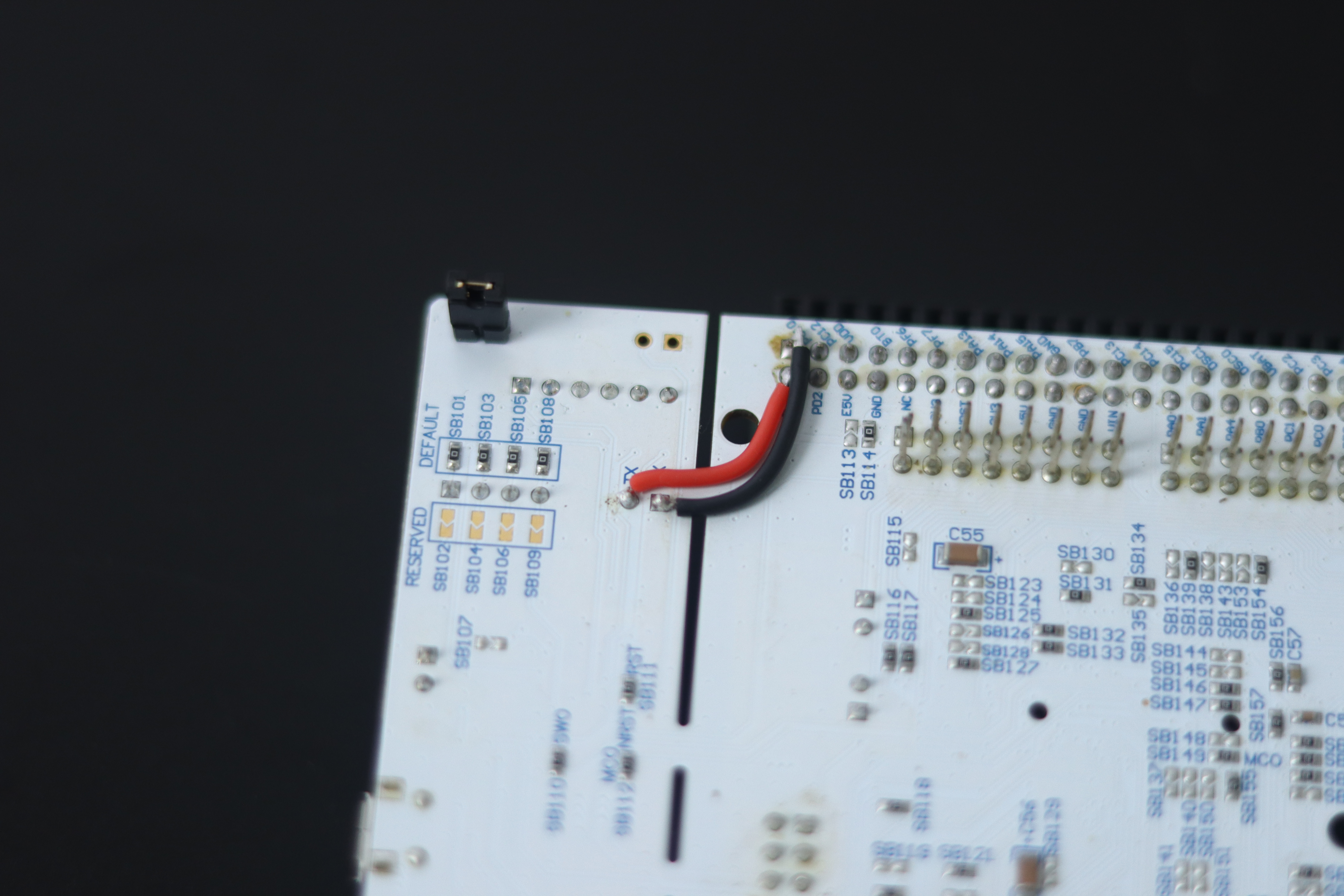
2. STM32 F429ZI
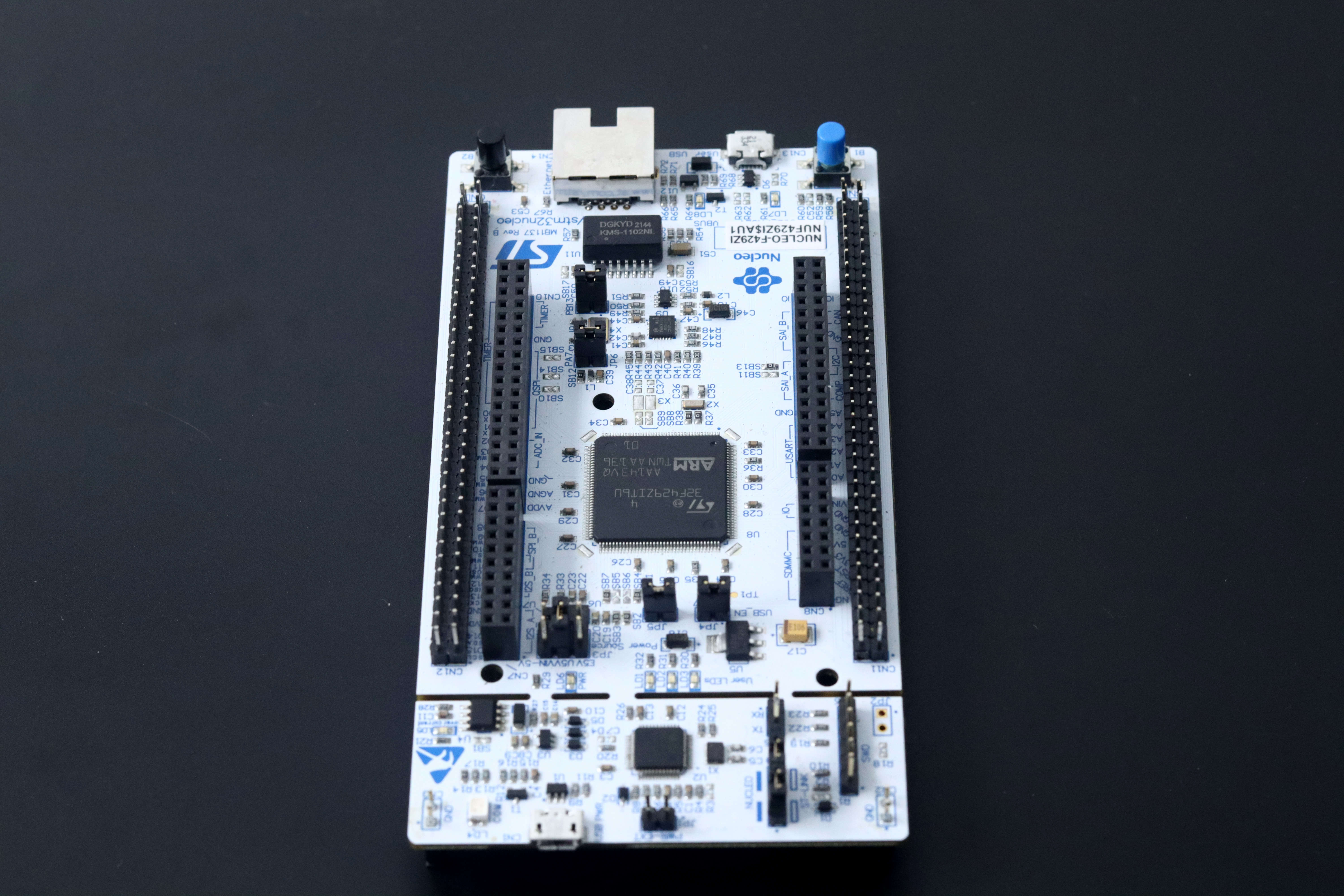
 A 5V 2A power brick is used to power the controller unit.
Firmware
#include <Arduino.h>
#include <Ethernet.h>
#include <PubSubClient.h>
#include <SPI.h>

/* Network */
#define SERVER_PORT 5000
#define MAX_CLIENT  8
byte mac[] = { 0xDE, 0xAD, 0xBE, 0xEF, 0xFE, 0xED };

const char* UID="KIT ID";

EthernetServer server(SERVER_PORT);
void print_network_info(void);

EthernetClient ethClient;
PubSubClient mqttClient(ethClient);

const char* mqttServer = "test.mosquitto.org";
const int mqttPort = 1883;
const char* mqttClientId = "myClientIDs";

// Array to store connected clients
EthernetClient clients[MAX_CLIENT];
EthernetClient client;

void setup() {
  Serial.begin(115200);
  Serial3.setRx(PC11);
  Serial3.setTx(PC10);

  Ethernet.begin(mac);
  IPAddress localIP = Ethernet.localIP();
  IPAddress modifiedIP(localIP[0], localIP[1], localIP[2], 6);
  Ethernet.begin(mac, modifiedIP);
  print_network_info();

  server.begin();
  Serial.print("Server is at ");
  Serial.println(Ethernet.localIP());

  mqttClient.setServer(mqttServer, mqttPort);
  mqttClient.setCallback(subscribeReceive);

  connectToMQTTServer();
}

void loop() {
  if (!mqttClient.connected()) {
    reconnectToMQTTServer();
  }
  mqttClient.loop();

  // Handle new client connections
  EthernetClient newClient = server.accept();
  if (newClient) {
    for (byte i = 0; i < MAX_CLIENT; i++) {
      if (!clients[i]) {
        Serial.printf("We have a new client # %d\r\n", i);
        clients[i] = newClient;
        break;
      }
    }
  }

  // Handle client data and publish to MQTT
  for (byte i = 0; i < MAX_CLIENT; i++) {
    if (clients[i] && clients[i].available() > 0) {
      byte buffer[80];
      int count = clients[i].read(buffer, 80);
      //Serial.write(buffer, count);

      if (count>0) {
        String topic = UID;
        String datum = String((char*)buffer);
        datum.trim();
        Serial.println(datum);
        if (mqttClient.publish(topic.c_str(), datum.c_str())) {
            //Serial.println(String((char*)buffer)+":");
            Serial.println("Publish message success");
            //break;
          } else {
            Serial.println("Publish message failed");
            //break;
          }
      }
    }

  }


  // Check for disconnected clients and remove them
  for (byte i = 0; i < MAX_CLIENT; i++) {
    if (clients[i] && !clients[i].connected()) {
      Serial.printf("Client #%d disconnected\r\n", i);
      clients[i].stop();
    }
  }
}

void connectToMQTTServer() {
  while (!mqttClient.connected()) {
    Serial.print("Connecting to MQTT server...");
    if (mqttClient.connect(mqttClientId)) {
      Serial.println("Connected");
      mqttClient.subscribe(UID);
    } else {
      Serial.print("Failed, retrying in 5 seconds...");
      delay(5000);
    }
  }
}

void reconnectToMQTTServer() {
  if (!mqttClient.connected()) {
    Serial.println("MQTT connection lost. Reconnecting...");
    connectToMQTTServer();
  }
}

void print_network_info(void) {
  byte print_mac[] = { 0, };
  Serial.println("\r\n-------------------------------------------------");
  Serial.printf("MAC        : ");
  Ethernet.MACAddress(print_mac);
  for (byte i = 0; i < 6; i++) {
    Serial.print(print_mac[i], HEX);
    if (i < 5) {
      Serial.print(":");
    }
  }
  Serial.println();
  Serial.printf("IP         : ");
  Serial.print(Ethernet.localIP());
  Serial.printf(": %d\r\n", SERVER_PORT);
  Serial.println("-------------------------------------------------");
}

void subscribeReceive(char* topic, byte* payload, unsigned int length) {
    for (byte i = 0; i < MAX_CLIENT; i++) {
      client = clients[i];
      if (client && client.connected()) {
        client.write(payload, length);
      }
    }
}
Node
1. WizFi360-EVB-Pico
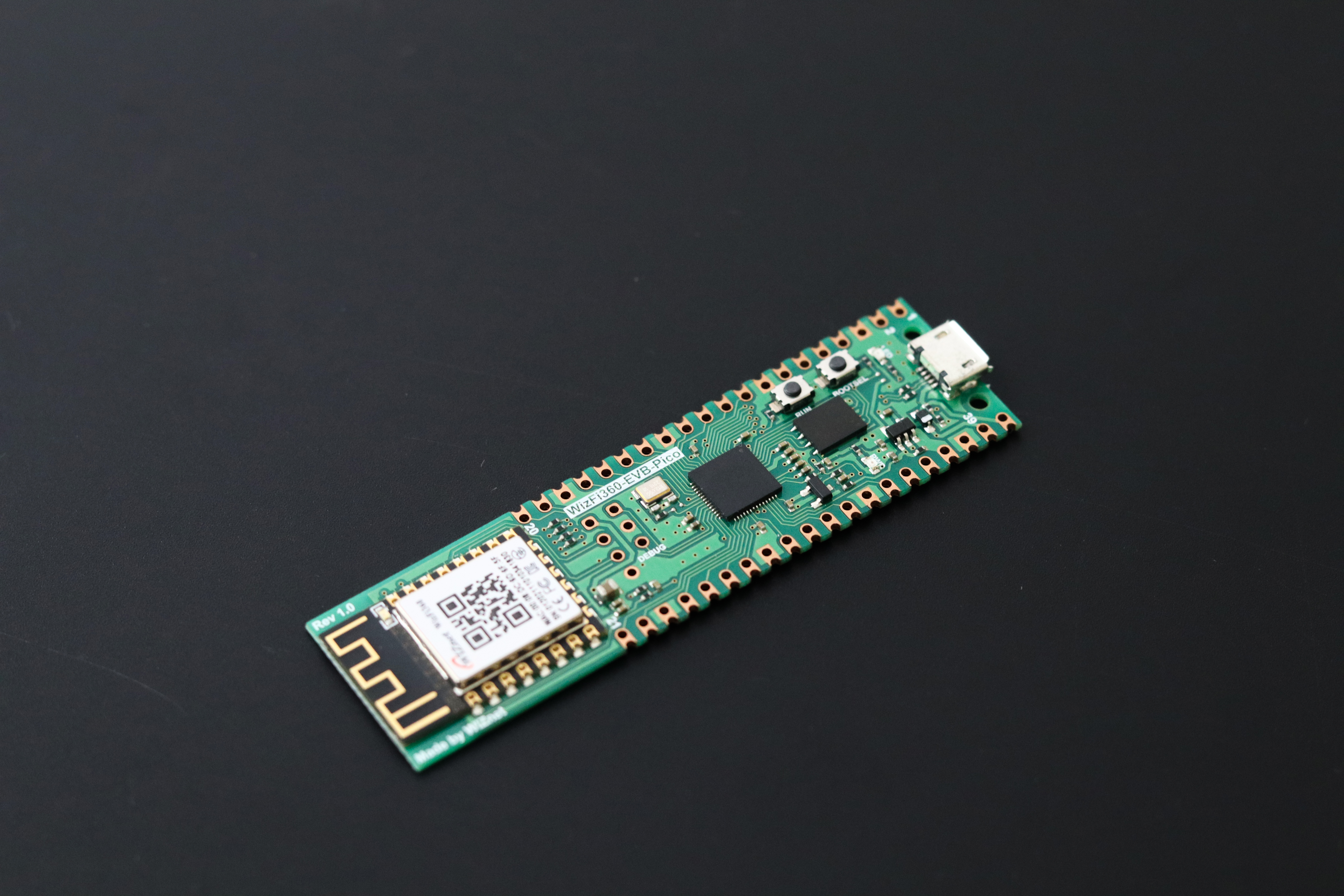
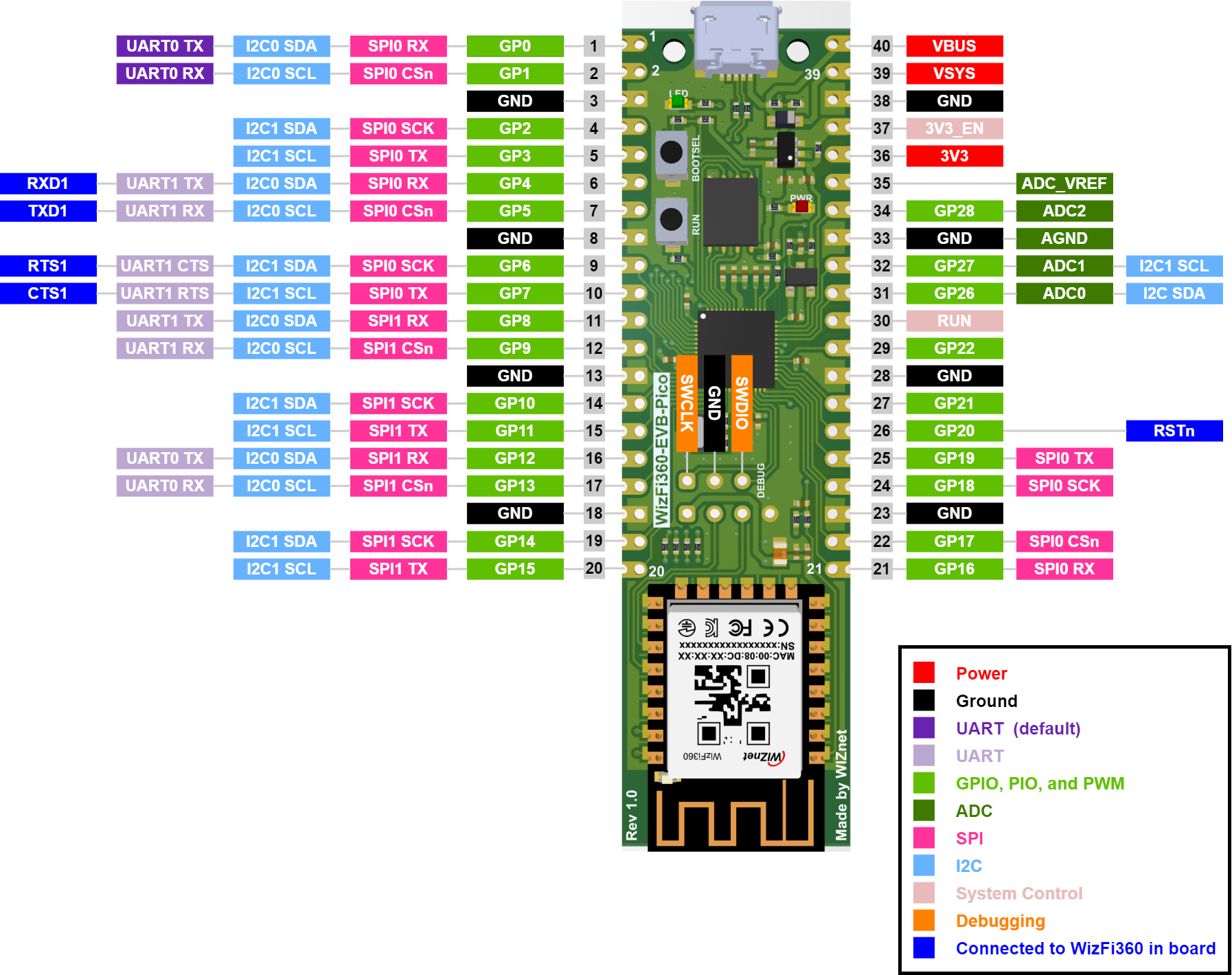
- Microcontroller: RP2040 with 2MByte Flash, dual-core Cortex-M0+ up to 133MHz, 264kByte SRAM, and Quad-SPI Flash (XIP).
- Wi-Fi Connectivity: Integrated WizFi360-PA module supporting 2.4GHz Wi-Fi (802.11 b/g/n).
- Operating Modes: Supports Station, SoftAP, SoftAP+Station, data pass-through, and AT command data transfer.
- Networking Modes: TCP Server, TCP Client, and UDP modes for versatile communication.
- Wireless Configuration: Channel selection (0-13), auto bandwidth (20MHz/40MHz), WPA_PSK/WPA2_PSK encryption.
- Industrial Grade: Operating temperature -40°C to 85°C, CE and FCC certified.
- Memory: Includes 16M-bit Flash Memory, micro-USB B port for power and data.
- Form Factor: 40-pin 21x51 'DIP' style PCB, 3-pin ARM SWD port, built-in LDO for voltage regulation.
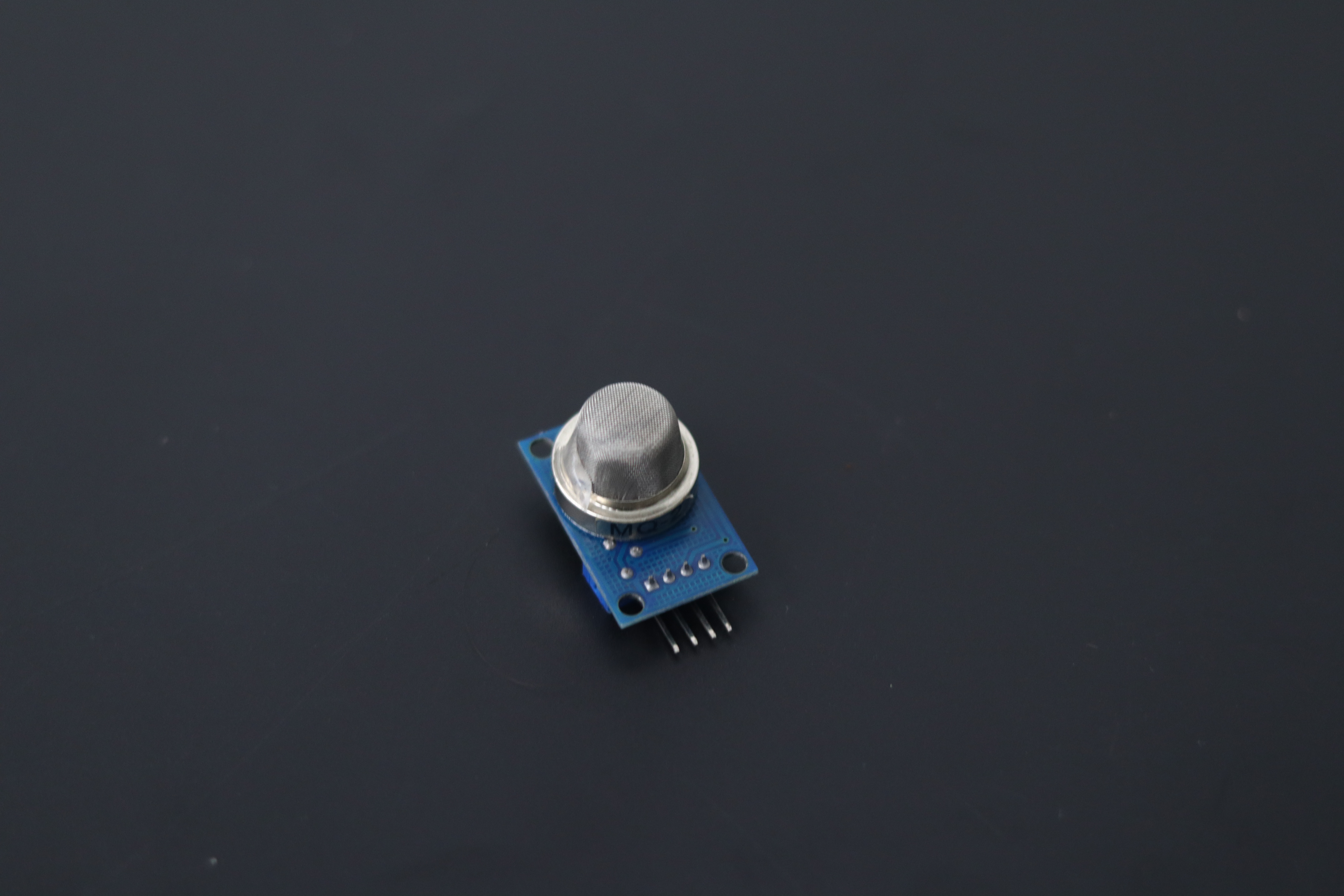
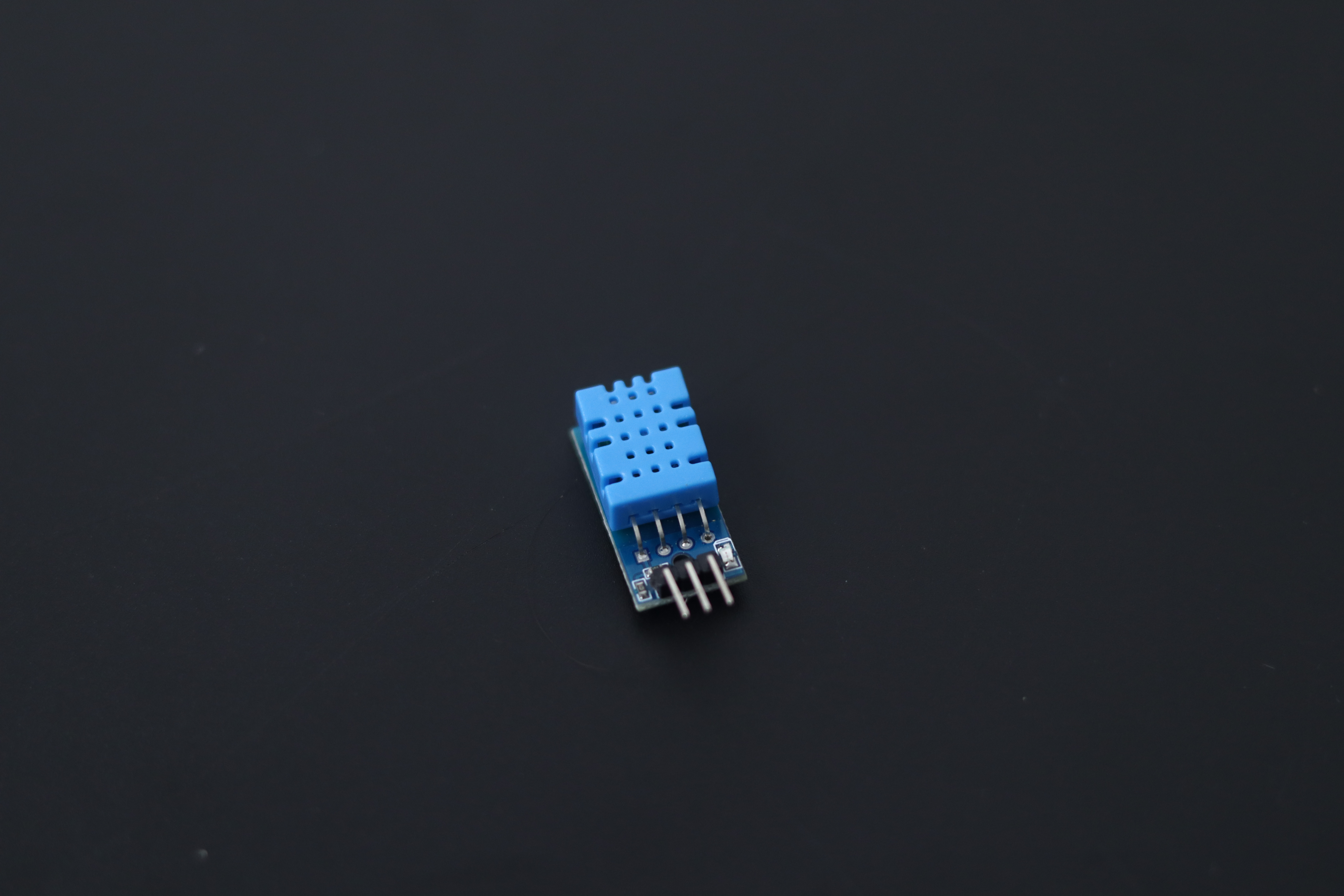
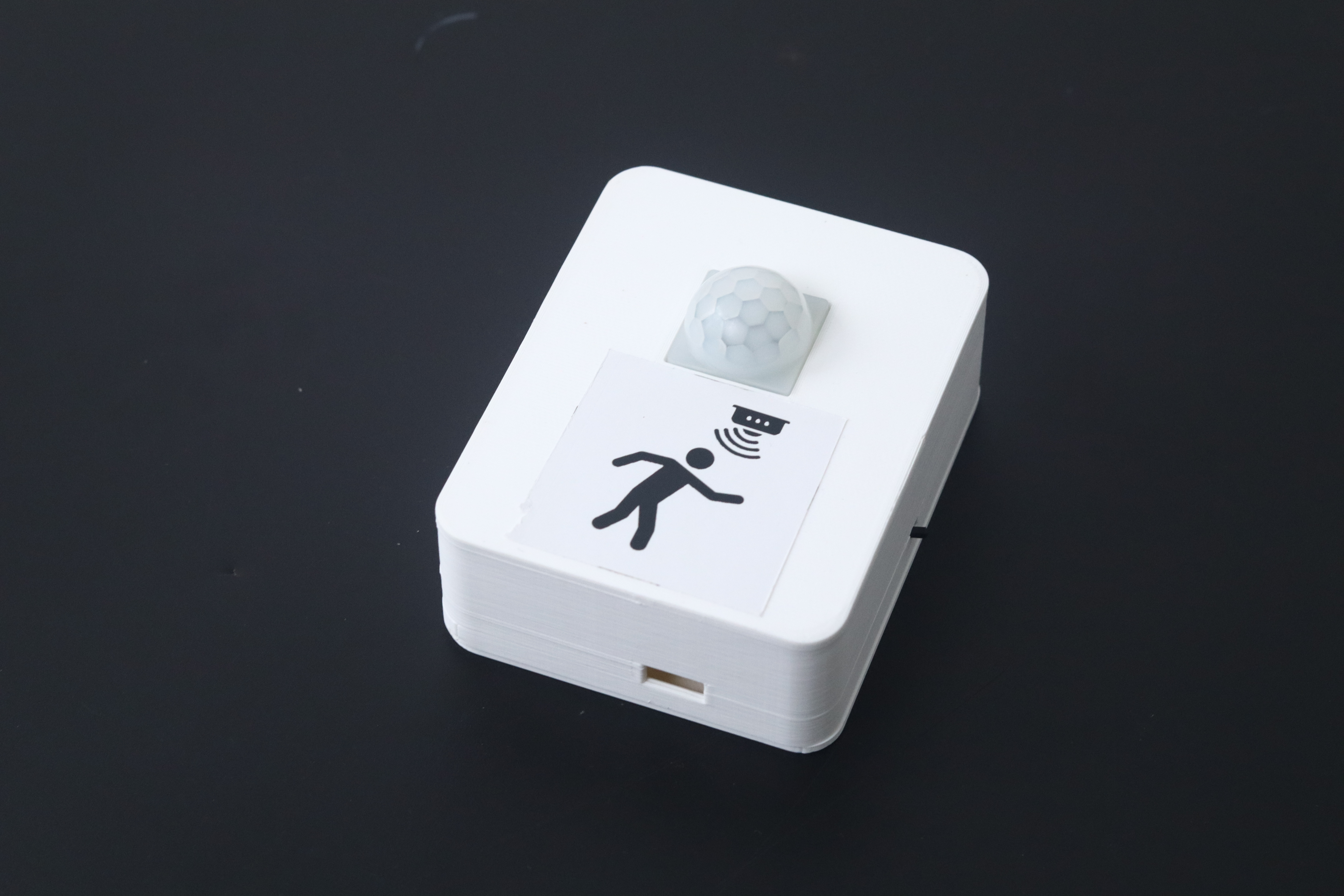
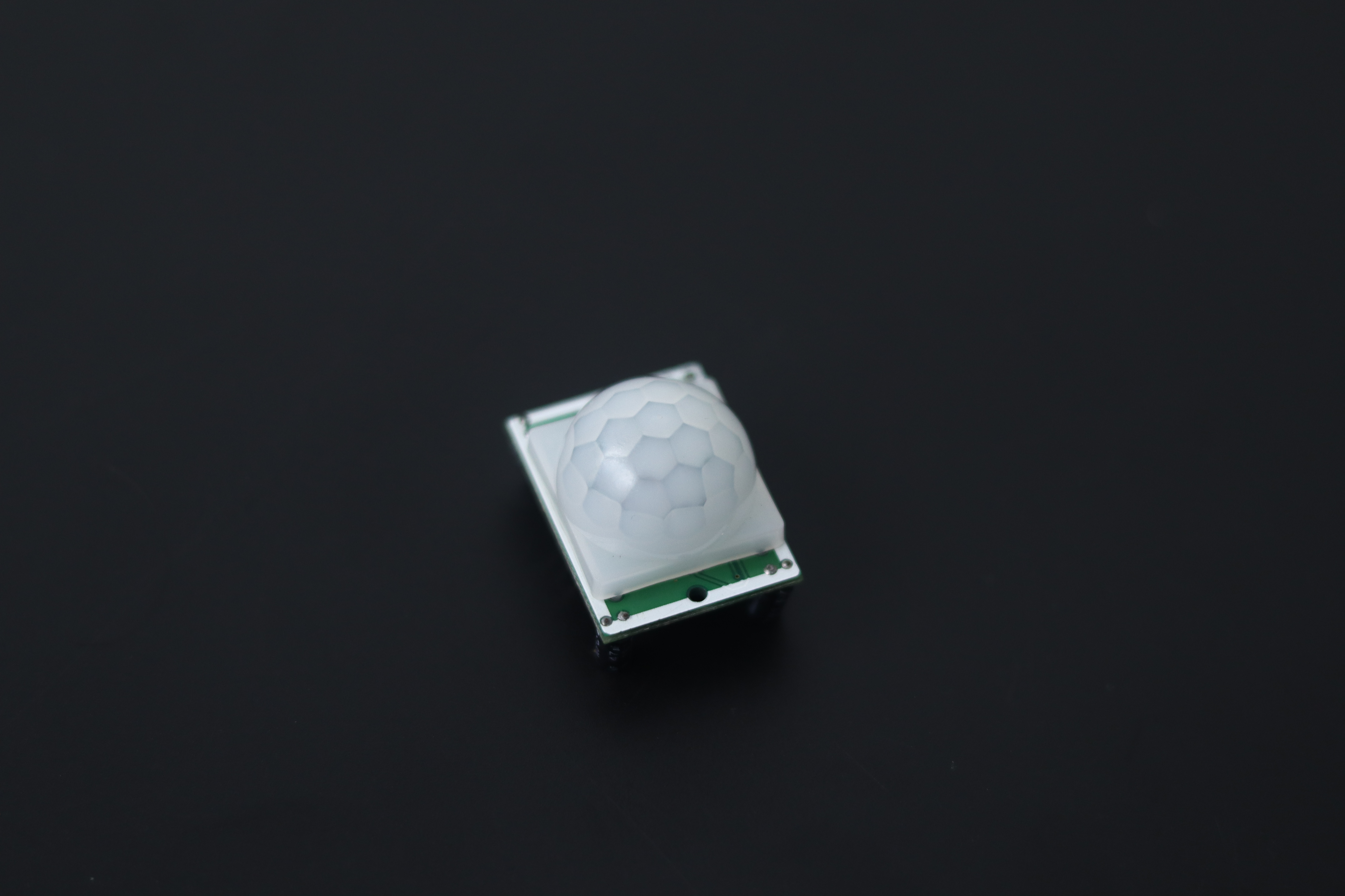
2. Sensors or Actuators
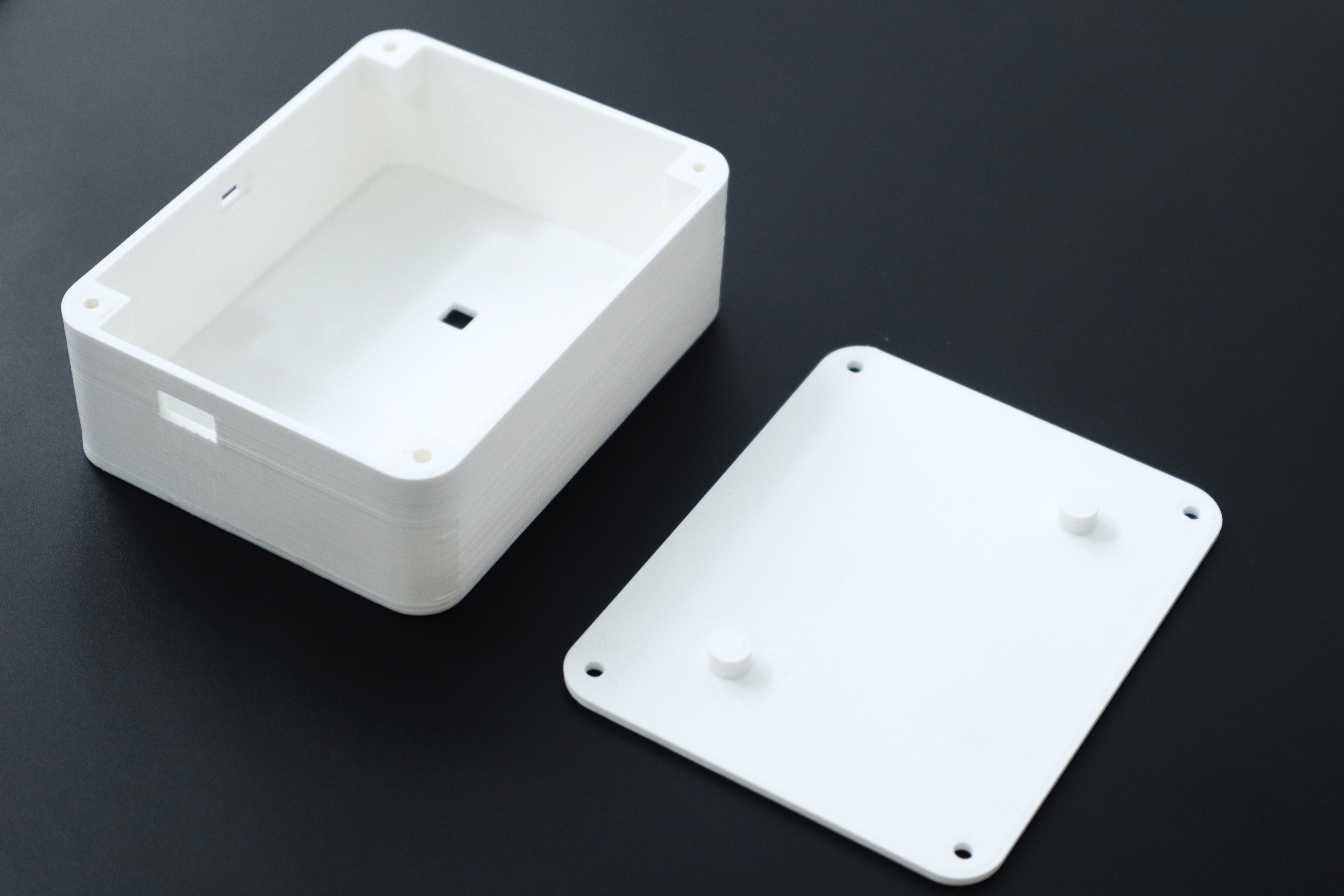
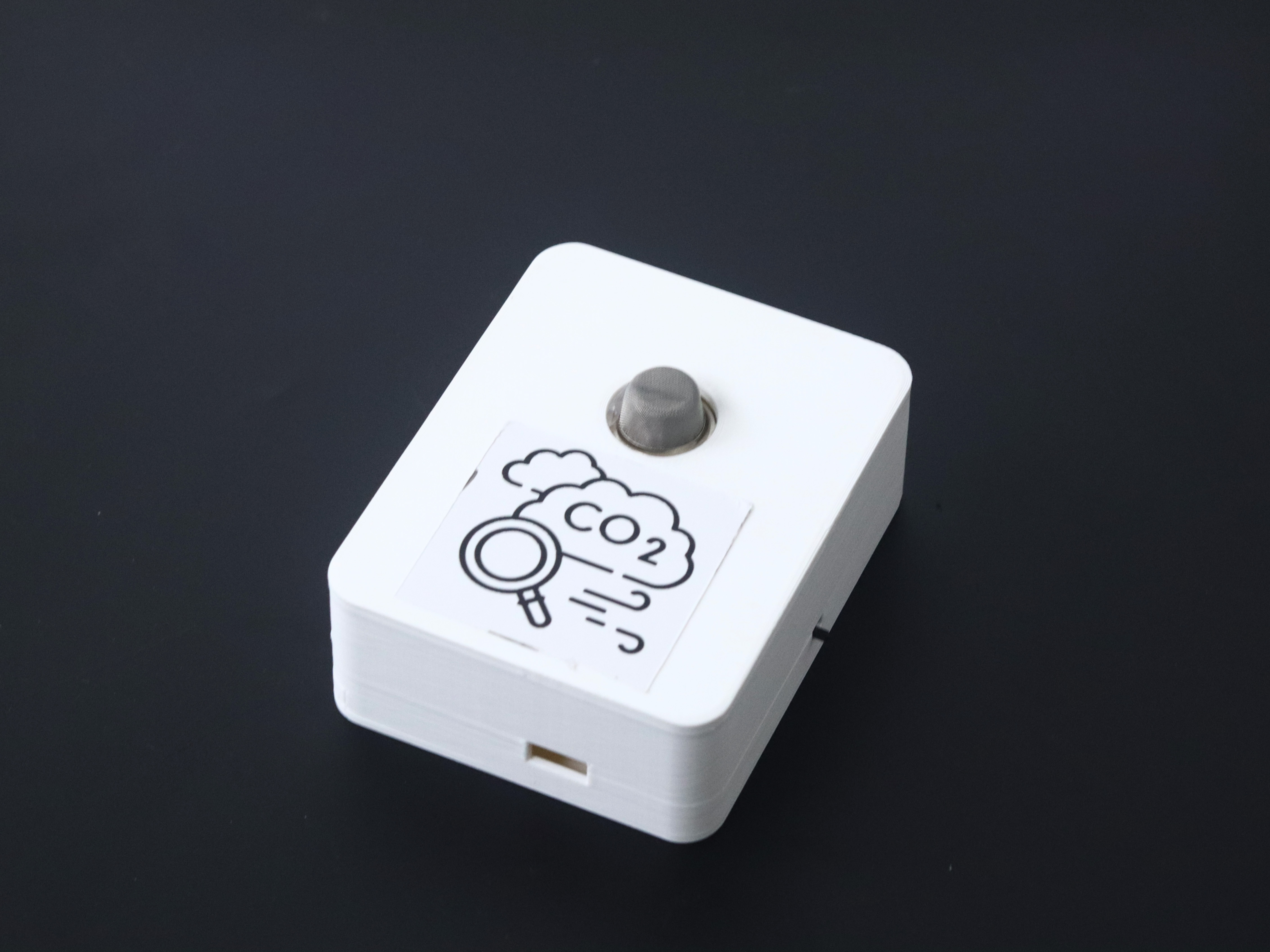
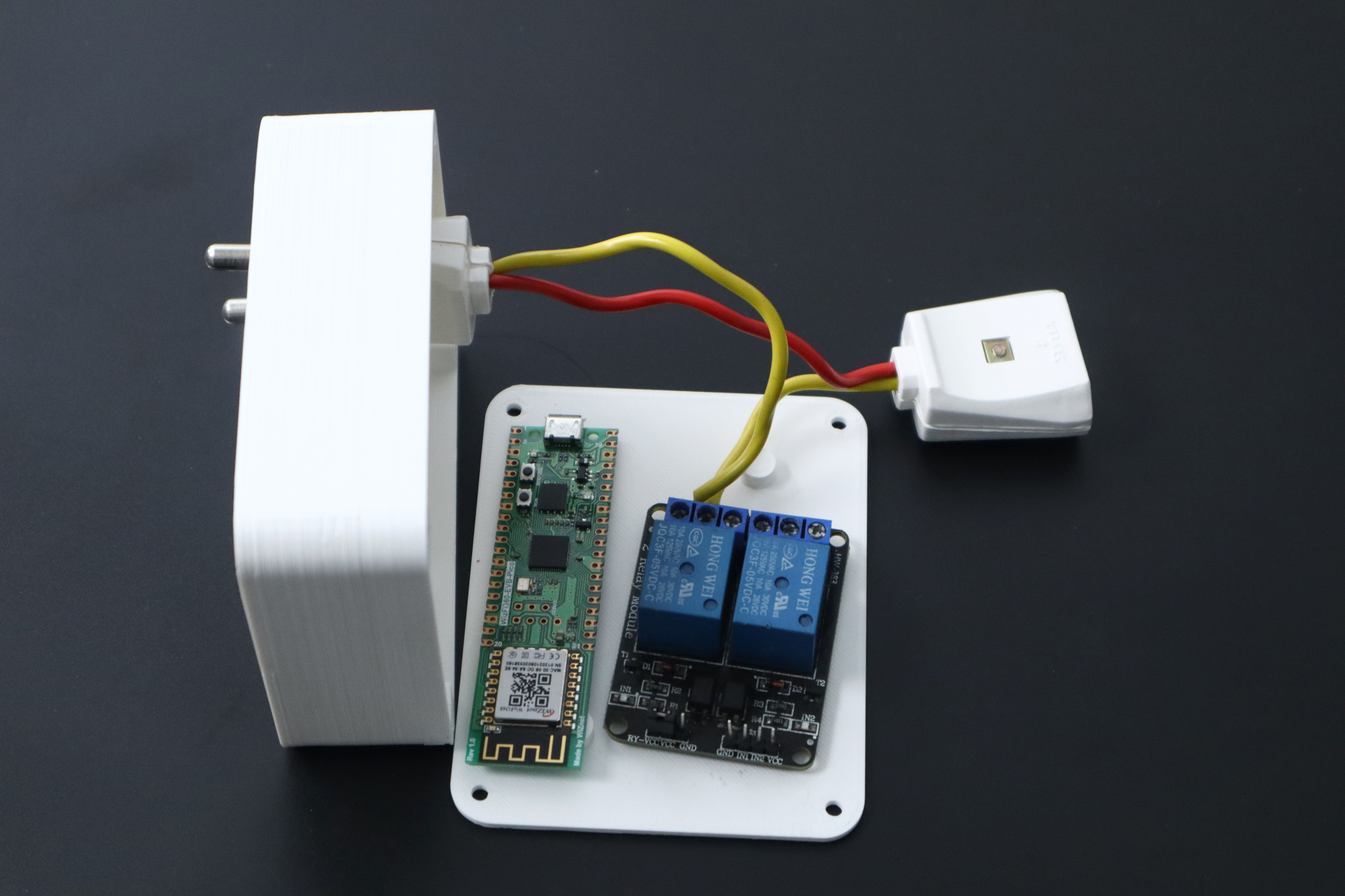
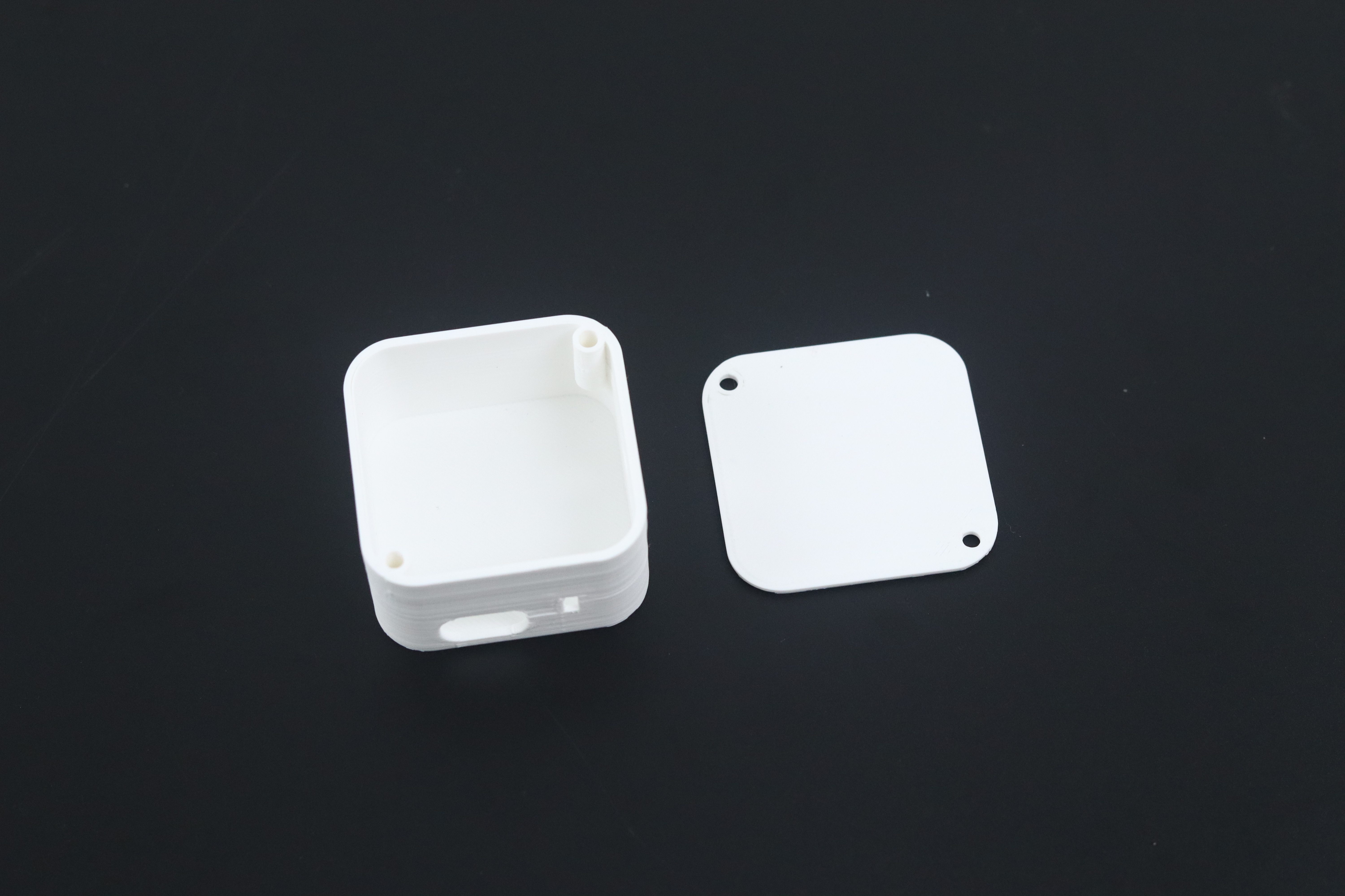
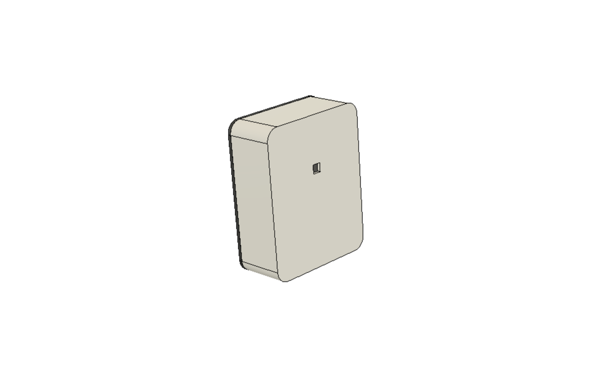 All the components will be enclosed in the case. The case design may vary depending on the sensor or actuator used.
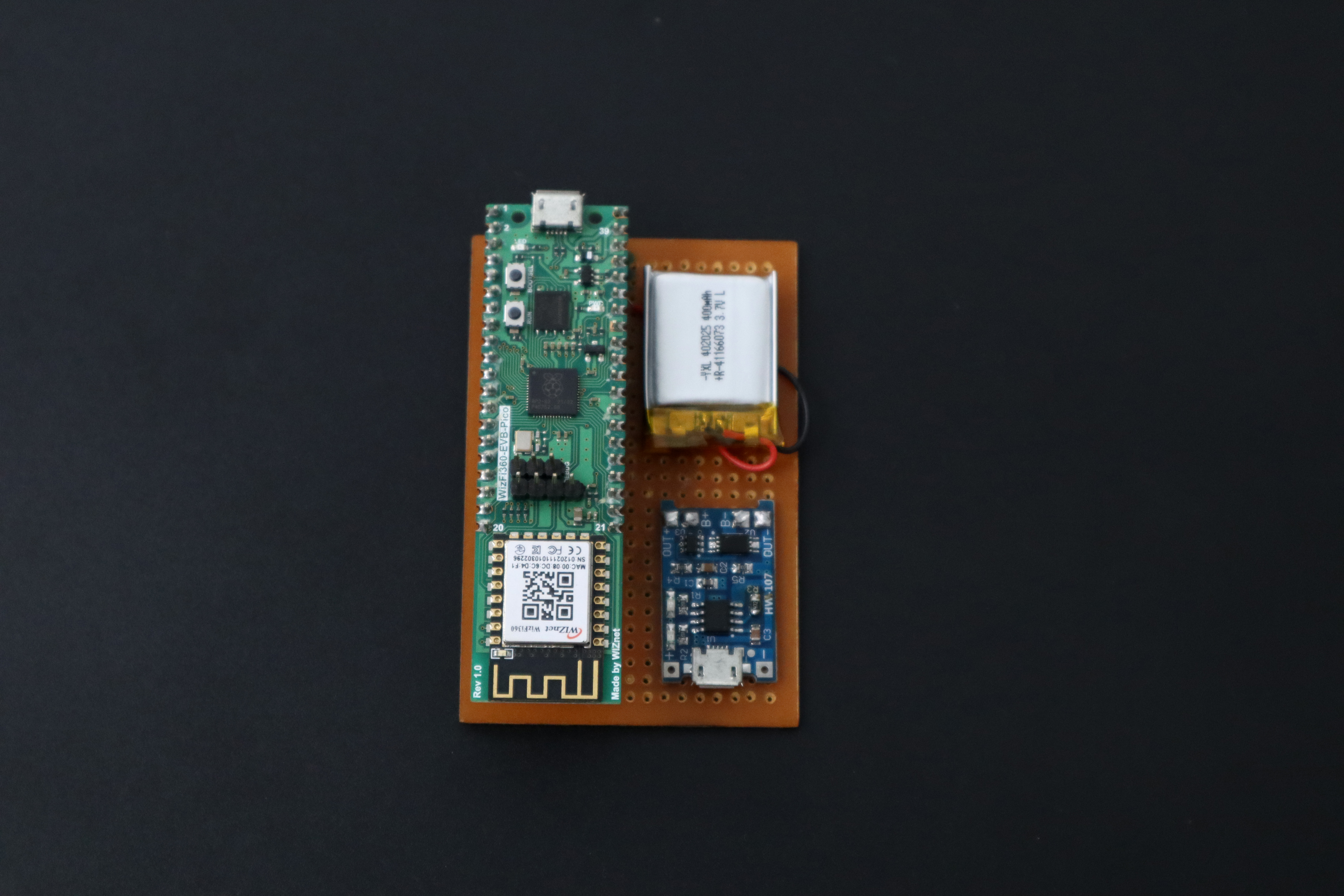
Note: WizFi360-EVB-Pico is a common component in all Nodes. All other components except this thing will change according to the sensor or actuator.
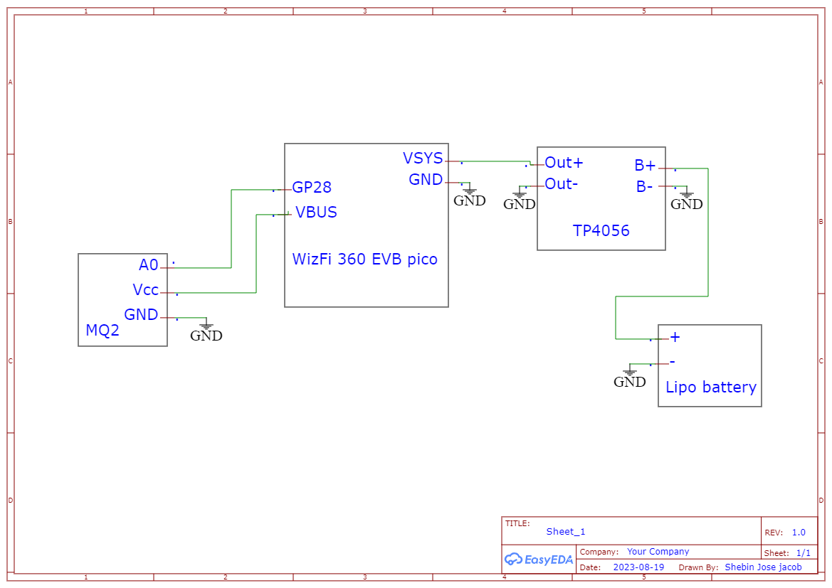
A sample code for a node to send data to ethernet server is shown below
#include "WizFi360.h"
#include <DHT.h>

// setup according to the device you use
#define WIZFI360_EVB_PICO

// Emulate Serial1 on pins 6/7 if not present
#ifndef HAVE_HWSERIAL1
#include "SoftwareSerial.h"
#if defined(ARDUINO_MEGA_2560)
SoftwareSerial Serial1(6, 7); // RX, TX
#elif defined(WIZFI360_EVB_PICO)
SoftwareSerial Serial2(6, 7); // RX, TX
#endif
#endif

/* Baudrate */
#define SERIAL_BAUDRATE   115200
#if defined(ARDUINO_MEGA_2560)
#define SERIAL1_BAUDRATE  115200
#elif defined(WIZFI360_EVB_PICO)
#define SERIAL2_BAUDRATE  115200
#endif

/* Wi-Fi info */
char ssid[] = "";       // your network SSID (name)
char pass[] = "";   // your network password

int status = WL_IDLE_STATUS;  // the Wifi radio's status

unsigned long lastConnectionTime = 0;         // last time you connected to the server, in milliseconds
const unsigned long postingInterval = 1000L; // delay between updates, in milliseconds

// Sensor
#define DHT_PIN 28
DHT dht(DHT_PIN, DHT11);

// Initialize the Ethernet client object
WiFiClient client;

void setup() {
  // initialize serial for debugging
  Serial.begin(SERIAL_BAUDRATE);
  // initialize serial for WizFi360 module
#if defined(ARDUINO_MEGA_2560)
  Serial1.begin(SERIAL1_BAUDRATE);
#elif defined(WIZFI360_EVB_PICO)
  Serial2.begin(SERIAL2_BAUDRATE);
#endif
  // initialize WizFi360 module
#if defined(ARDUINO_MEGA_2560)
  WiFi.init(&Serial1);
#elif defined(WIZFI360_EVB_PICO)
  WiFi.init(&Serial2);
#endif

  // check for the presence of the shield
  if (WiFi.status() == WL_NO_SHIELD) {
    Serial.println("WiFi shield not present");
    // don't continue
    while (true);
  }

  // attempt to connect to WiFi network
  while (status != WL_CONNECTED) {
    Serial.print("Attempting to connect to WPA SSID: ");
    Serial.println(ssid);
    // Connect to WPA/WPA2 network
    status = WiFi.begin(ssid, pass);
  }

  Serial.println("You're connected to the network");

  printWifiStatus();

  dht.begin();
}

void loop() {
  // if there's incoming data from the net connection send it out the serial port
  // this is for debugging purposes only
  while (client.available()) {
    char c = client.read();
    Serial.write(c);
  }

  // if 10 seconds have passed since your last connection,
  // then connect again and send data
  if (millis() - lastConnectionTime > postingInterval) {
    httpRequest();
  }
}

// this method makes an HTTP connection to the server
void httpRequest() {
  IPAddress server = WiFi.localIP();
  server[3] = 6;
  Serial.println(server);
  Serial.println();
  float temperature = dht.readTemperature();
  float humidity = dht.readHumidity();
  Serial.print("Temp: ");
  Serial.print(temperature);
  Serial.println();

  // close any connection before sending a new request
  // this will free the socket on the WiFi shield
  //client.stop();

  // if there's a successful connection
  if (client.connect(server, 5000)) {
    Serial.println("Connected");
    String TempData = "TEMP:"+String(temperature);
    String HumidityData = "HUMIDITY:"+String(humidity);
    Serial.println(TempData);
    // send the HTTP PUT request
    client.print(TempData);
    client.println();
    client.print(HumidityData);
    Serial.println("Message Sent");
    client.stop();

    // note the time that the connection was made
    lastConnectionTime = millis();
  }
  else {
    // if you couldn't make a connection
    Serial.println("Connection failed");
    delay(100);
  }
}

void printWifiStatus() {
  // print the SSID of the network you're attached to
  Serial.print("SSID: ");
  Serial.println(WiFi.SSID());

  // print your WiFi shield's IP address
  IPAddress ip = WiFi.localIP();
  Serial.print("IP Address: ");
  Serial.println(ip);

  // print the received signal strength
  long rssi = WiFi.RSSI();
  Serial.print("Signal strength (RSSI):");
  Serial.print(rssi);
  Serial.println(" dBm");
}
#include "WizFi360.h"
#include "provision.h"
#include <EEPROM.h>

// setup according to the device you use
#define WIZFI360_EVB_PICO

// Emulate Serial1 on pins 6/7 if not present
#ifndef HAVE_HWSERIAL1
#include "SoftwareSerial.h"
#if defined(ARDUINO_MEGA_2560)
SoftwareSerial Serial1(6, 7); // RX, TX
#elif defined(WIZFI360_EVB_PICO)
SoftwareSerial Serial2(6, 7); // RX, TX
#endif
#endif
/* Baudrate */
#define SERIAL_BAUDRATE   115200
#if defined(ARDUINO_MEGA_2560)
#define SERIAL1_BAUDRATE  115200
#elif defined(WIZFI360_EVB_PICO)
#define SERIAL2_BAUDRATE  115200
#endif

char ap_ssid[] = "wiznet";
char ap_pass[] = "0123456789";

int status = WL_IDLE_STATUS;

WiFiServer server(80);

char ssid[32]; // Max SSID length
char pass[64]; // Max password length
const int ssidAddress = 0;
const int passAddress = ssidAddress + sizeof(ssid);


void setup() {
  // initialize serial for debugging
  Serial.begin(SERIAL_BAUDRATE);
  // initialize serial for WizFi360 module
#if defined(ARDUINO_MEGA_2560)
  Serial1.begin(SERIAL1_BAUDRATE);
#elif defined(WIZFI360_EVB_PICO)
  Serial2.begin(SERIAL2_BAUDRATE);
#endif
  // initialize WizFi360 module
#if defined(ARDUINO_MEGA_2560)
  WiFi.init(&Serial1);
#elif defined(WIZFI360_EVB_PICO)
  WiFi.init(&Serial2);
#endif


  if (WiFi.status() == WL_NO_SHIELD) {
    Serial.println("WiFi shield not present");
    while (true);
  }

  EEPROM.get(ssidAddress, ssid);
  EEPROM.get(passAddress, pass);

  Serial.print("Attempting to start AP ");
  Serial.println(ssid);

  if (ssid[0] == '\0' || pass[0] == '\0') {
    Serial.println(ssid);
    startAPMode();
  } else {
    connectToWiFi();
  }
  printWifiStatus();

  server.begin();
  Serial.println("Server started");
}

void loop() {
  WiFiClient client = server.available();

  if (client) {
    Serial.println("New client");
    String request = "";
    while (client.connected()) {
      if (client.available()) {
        char c = client.read();
        request += c;

        if (request.endsWith("\r\n\r\n")) {
          if (request.indexOf("GET /submit") != -1) {
            handleFormSubmission(client, request);
          } else {
            sendHtmlForm(client);
          }
          break;
        }
      }
    }

    delay(10);
    client.stop();
    Serial.println("Client disconnected");
  }
}

void sendHtmlForm(WiFiClient client) {
  client.print(
    "HTTP/1.1 200 OK\r\n"
    "Content-Type: text/html\r\n"
    "Connection: close\r\n"
    "\r\n");
  client.println(home_0);
  client.println(home_1);
  client.println(home_2);
  client.println(home_3);

}

void handleFormSubmission(WiFiClient client, String request) {
  String ssidValue, passwordValue;
  getSsidAndPasswordFromRequest(request, ssidValue, passwordValue);

  Serial.println("Entered SSID: " + ssidValue);
  Serial.println("Entered Password: " + passwordValue);

  // Store credentials in EEPROM
  ssidValue.toCharArray(ssid, sizeof(ssid));
  passwordValue.toCharArray(pass, sizeof(pass));
  Serial.println(ssid);
  Serial.println(pass);
  EEPROM.put(ssidAddress, ssid);
  EEPROM.put(passAddress, pass);
  EEPROM.commit();

  Serial.println("Values in EEPROM:");
  Serial.println("SSID: " + String(ssid));
  Serial.println("Password: " + String(pass));

  client.print(
    "HTTP/1.1 200 OK\r\n"
    "Content-Type: text/html\r\n"
    "Connection: close\r\n"
    "\r\n");
  client.print(response_0);

  //resetWizFi360();
  delay(5000);

resetWiFiModule();
  delay(1000);
  connectToWiFi();
}

void startAPMode() {
  // Start access point and set up web server
  WiFi.beginAP(ap_ssid, 10, ap_pass, ENC_TYPE_WPA2_PSK);
  IPAddress localIp(192, 168, 2, 100);
  WiFi.configAP(localIp);

  // Set up the web server for configuration
  server.begin();
  Serial.println("Access point started");
  Serial.println("Server started");
}

void connectToWiFi() {
  WiFi.disconnect(); // Disconnect from any previous connections
  Serial.println("SSID: "+String(ssid));
  Serial.println("Password: "+String(pass));
  WiFi.begin(ssid, pass);
  int retry = 0;
  while (WiFi.status() != WL_CONNECTED && retry < 10) {
    delay(1000);
    Serial.println("Connecting to WiFi...");
    retry++;
  }

  if (WiFi.status() == WL_CONNECTED) {
    Serial.println("Connected to WiFi");
  } else {
    Serial.println("Failed to connect to WiFi");
    startAPMode(); // Enter AP mode if failed to connect
  }
}

void getSsidAndPasswordFromRequest(String request, String &ssidValue, String &passwordValue) {
  int ssidIndex = request.indexOf("ssid=");
  int passwordIndex = request.indexOf("password=");
  int spaceIndex = request.indexOf("HTTP/1.1");

  if (ssidIndex != -1 && passwordIndex != -1 && spaceIndex != -1) {
    ssidValue = request.substring(ssidIndex + 5, passwordIndex - 1); // 5 is the length of "ssid="
    passwordValue = request.substring(passwordIndex + 9, spaceIndex-1); // 9 is the length of "password="
  } else {
    ssidValue = "";
    passwordValue = "";
  }
}


void printWifiStatus() {
  // print the SSID of the network you're attached to
  Serial.print("SSID: ");
  Serial.println(WiFi.SSID());

  // print your WiFi shield's IP address
  IPAddress ip = WiFi.localIP();
  Serial.print("IP Address: ");
  Serial.println(ip);

  // print the received signal strength
  long rssi = WiFi.RSSI();
  Serial.print("Signal strength (RSSI):");
  Serial.print(rssi);
  Serial.println(" dBm");
}

void resetWiFiModule() {
  WiFi.disconnect();
  delay(1000); // Wait for module to fully disconnect
  WiFi.init(&Serial2); // Initialize WiFi module again

  Serial.println("WiFi module reset");
}


Deploying Modular IoT in the Low Energy Realm with BLE
In our relentless pursuit of innovation, we have extended the boundaries of the Modular IoT Kit to a BLE (Bluetooth Low Energy) variant, ushering in a new era of efficiency and longevity within the realm of low-energy IoT applications. With an emphasis on prolonging the lifespan of battery-powered nodes, while optimizing their size, our BLE variant stands as a testament to our commitment to cutting-edge solutions.
One of the cornerstones of this evolution is the strategic incorporation of BLE technology. Designed to minimize power consumption, BLE ensures that nodes equipped with smaller batteries can operate significantly longer, extending their operational lifetime and minimizing maintenance requirements. This optimization paves the way for smaller node designs, seamlessly merging energy efficiency with compact form factors.
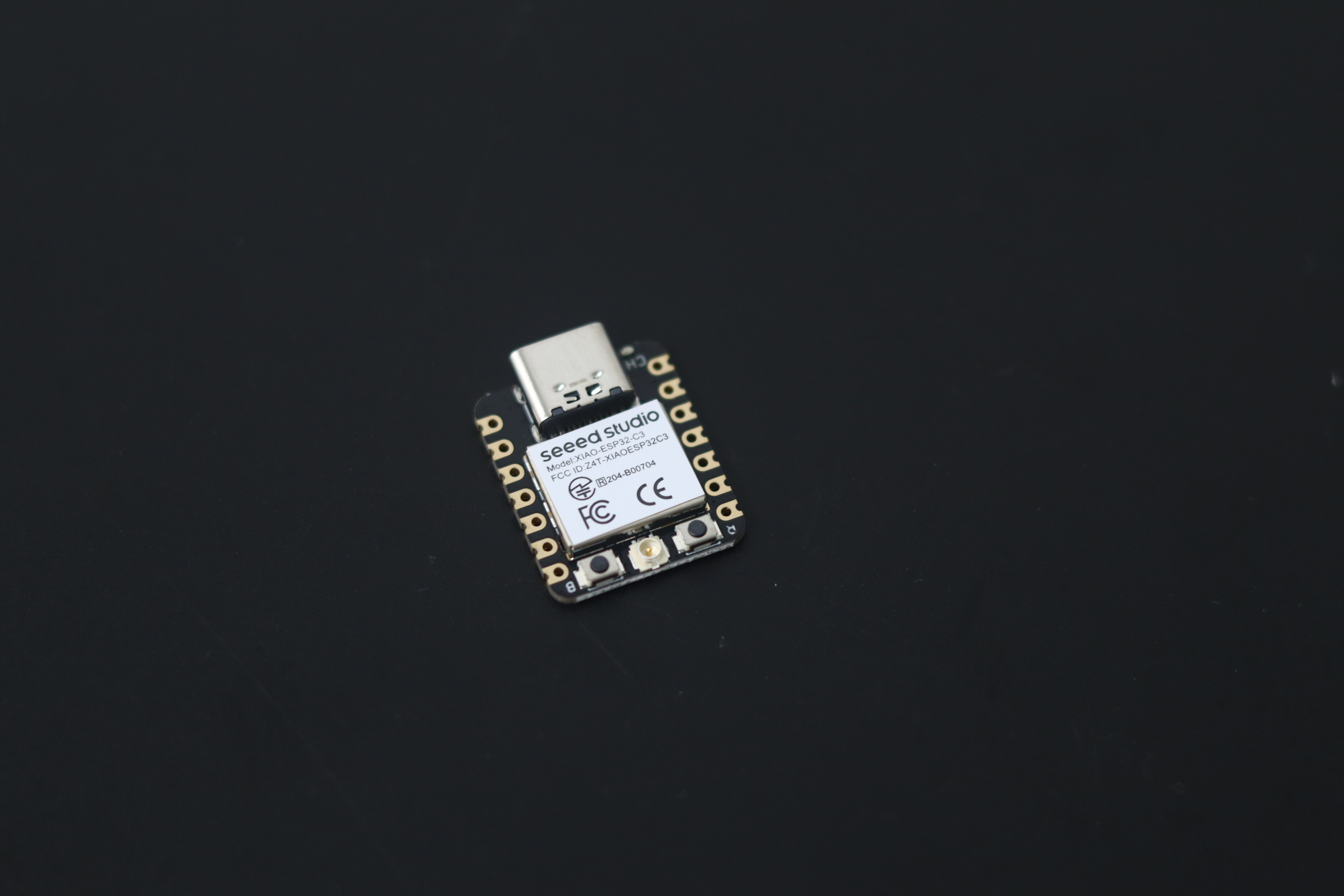
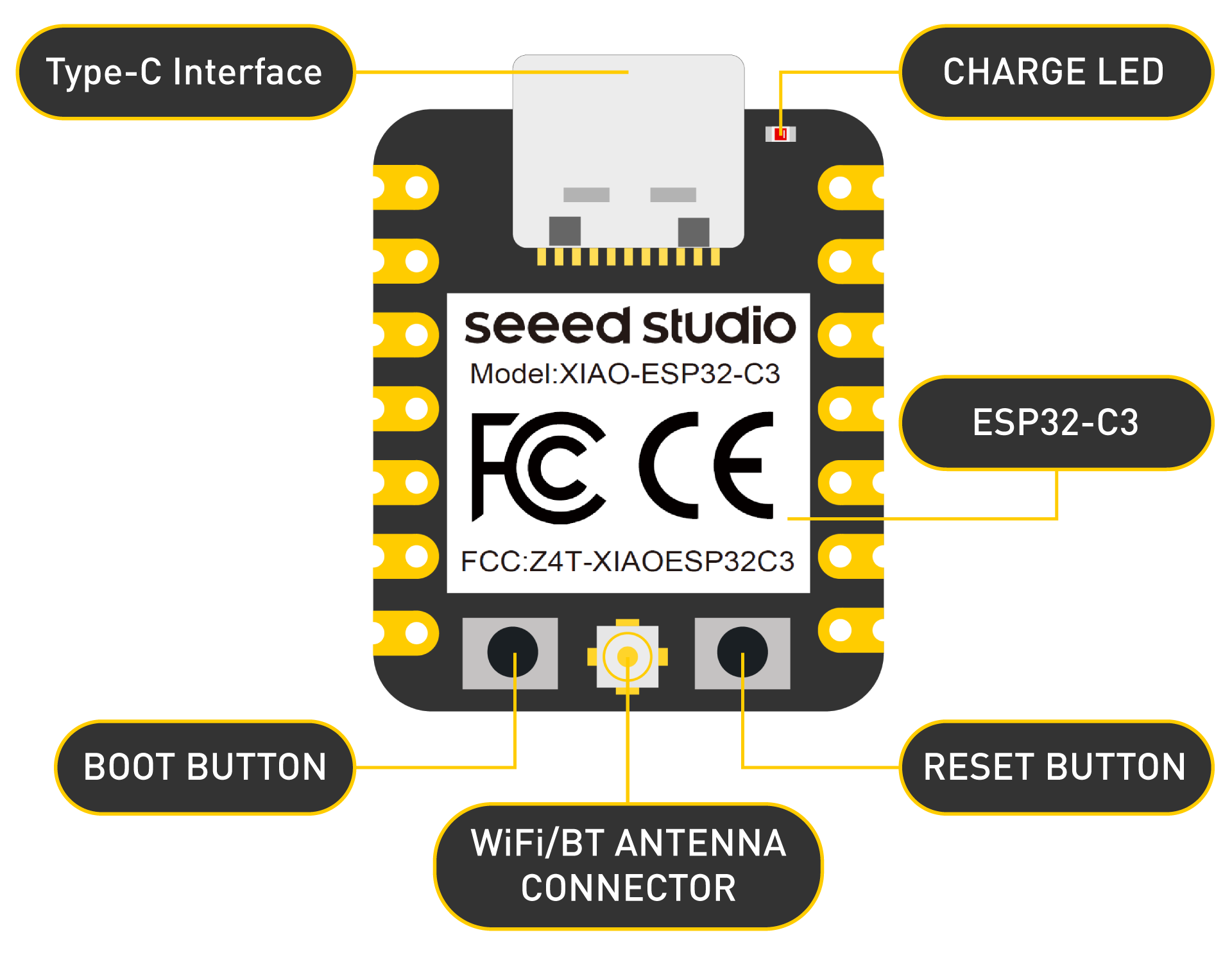
Architecturally distinct from its predecessor, the BLE variant unveils a refined architecture to cater to its unique demands. At the heart of the gateway lies the W5300 chipset, synergistically coupled with the STM32 F429ZI microcontroller. Serially integrated with the Seeed Studio Xiao ESP32C3, this combination enables BLE connectivity to the gateway, thereby enriching the interaction possibilities. Notably, the ESP32C3 assumes the role of a multi-connect BLE server, accommodating simultaneous connections from multiple BLE clients—a pivotal enhancement in scalability.
Within this architecture, data flow is meticulously orchestrated. Data received from BLE clients is seamlessly relayed to the STM32F429ZI microcontroller through a serial port connection. Subsequently, this data is directed to the W5300 chipset, where it is encapsulated for MQTT transmission. The 16-bit bus in W5300 TOE Shield enables the real-time transfer of data between STM32 F429ZI and W5300 without any delays. Leveraging the ethernet client encapsulated with the pub-sub client, data is then efficiently transmitted to the MQTT broker—a seamless journey from BLE to MQTT.
Turning our attention to the node side, the Xiao ESP32C3 once again takes center stage. Here, it operates in BLE client mode, effectively facilitating bidirectional data exchange with the server. This communication dynamic underscores the interoperability of our ecosystem, where the BLE-enabled nodes actively engage in data exchange with the gateway.
Undoubtedly, the smaller form factor and optimized energy consumption of the Xiao ESP32C3 emerge as pivotal features on the node side. These attributes collectively translate into nodes that are not only compact but also demonstrate an extended operational lifespan—a synthesis of technology and innovation.
By integrating BLE technology, we introduce a new chapter in low-energy IoT landscapes, exemplifying our commitment to innovation.
Topology and Data Flow
Gateway
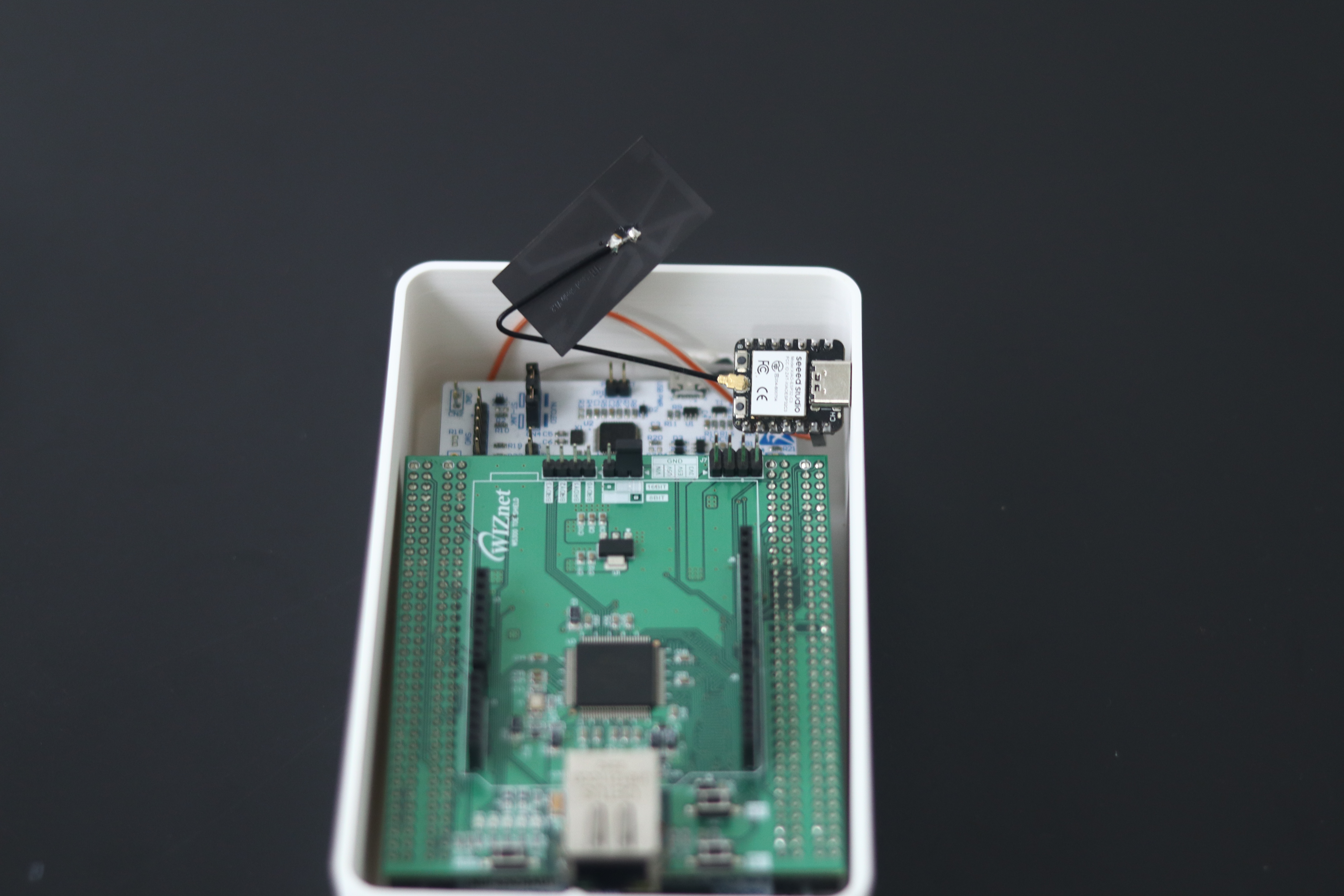
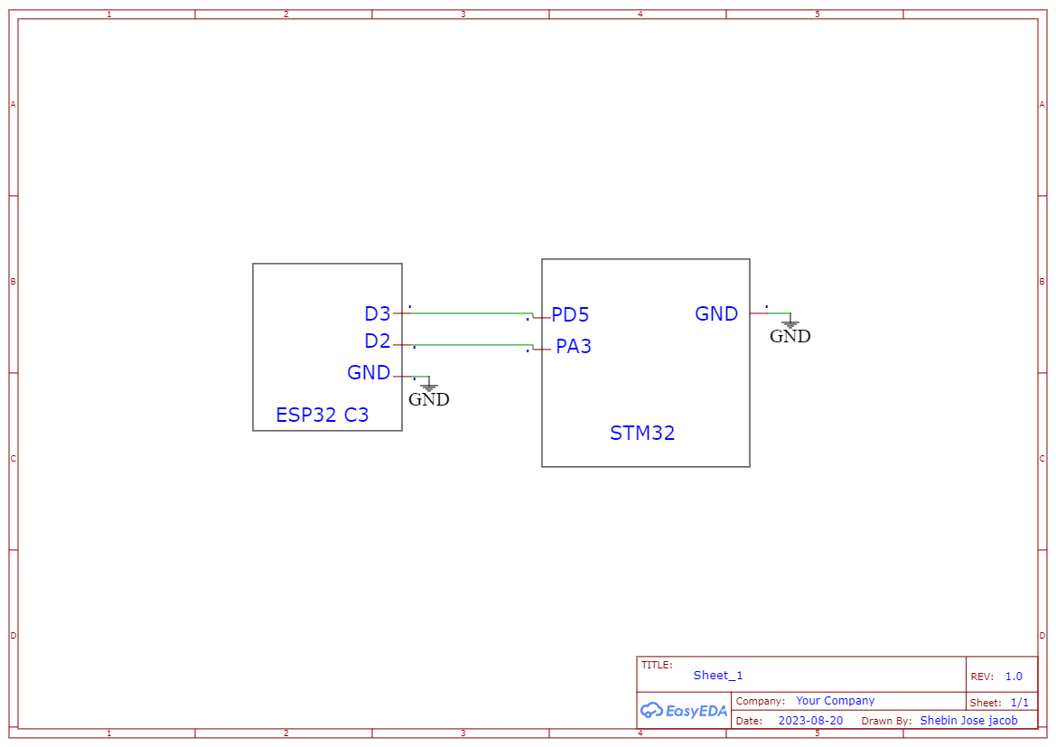
In the Bluetooth variant also the gateway is comprised of a W5300 TOE shield and STM32 Nucleo 144 F429ZI. In addition to that ESP32 C3 will be added to the gateway for giving Bluetooth capability.
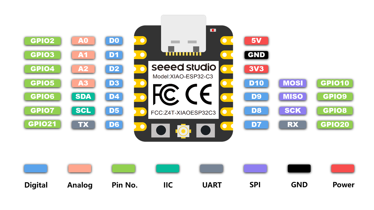
The ESP32C3 serially communicates with Nucleo 144 to pass and retrieve data from Nucleo 144. The USART2 (PA3 & PD5) of the STM32 Nucleo 144 is used for communication. The communication speed of the W5300 TOE (TCP/IP Offload Engine) shield is a significant advantage in this scenario, particularly in the context of high-speed data exchange between the STM32 Nucleo 144 and the W5300 TOE Shield.
Firmware
We have developed the code for STM32 F429ZI coupled with W5300 to create an ethernet client and to serially read from the USART2 port of STM32 F429ZI.
#include <Ethernet.h>
#include <PubSubClient.h>
#include <SPI.h>
#include <HardwareSerial.h>

HardwareSerial Serial2(PA3,PD5);

cons char* UID = "KIT ID";

/* Network */
byte mac[] = { 0xDE, 0xAD, 0xBE, 0xEF, 0xFE, 0xED };

EthernetClient ethClient;
PubSubClient mqttClient(ethClient);

const char* mqttServer = "test.mosquitto.org";
const int mqttPort = 1883;
const char* mqttClientId = "myClientIDs";


void connectToMQTTServer() {
  while (!mqttClient.connected()) {
    Serial.print("Connecting to MQTT server...");
    if (mqttClient.connect(mqttClientId)) {
      Serial.println("Connected");
      mqttClient.subscribe(UID);
    } else {
      Serial.print("Failed, retrying in 5 seconds...");
      delay(5000);
    }
  }
}

void reconnectToMQTTServer() {
  if (!mqttClient.connected()) {
    Serial.println("MQTT connection lost. Reconnecting...");
    connectToMQTTServer();
  }
}

void print_network_info(void) {
  byte print_mac[] = { 0, };
  Serial.println("\r\n-------------------------------------------------");
  Serial.printf("MAC        : ");
  Ethernet.MACAddress(print_mac);
  for (byte i = 0; i < 6; i++) {
    Serial.print(print_mac[i], HEX);
    if (i < 5) {
      Serial.print(":");
    }
  }
  Serial.println();
  Serial.printf("IP         : ");
  Serial.print(Ethernet.localIP());
  Serial.println("-------------------------------------------------");
}


void setup() {
  Serial.begin(115200);
  Serial3.setRx(PC11);
  Serial3.setTx(PC10);
  Serial2.begin(9600);

  Ethernet.begin(mac);
  IPAddress localIP = Ethernet.localIP();
  IPAddress modifiedIP(localIP[0], localIP[1], localIP[2], 5);
  Ethernet.begin(mac, modifiedIP);
  print_network_info();

  mqttClient.setServer(mqttServer, mqttPort);
  //mqttClient.setCallback(subscribeReceive);
  mqttClient.subscribe(UID);
  connectToMQTTServer();
}

void loop() {
  if (!mqttClient.connected()) {
    reconnectToMQTTServer();
  }
  mqttClient.loop();

  if (Serial2.available() > 0) {
        String sensorData = Serial2.readStringUntil('\n');
        sensorData.trim(); // Remove leading/trailing whitespace characters
        String topic = UID;
        String datum = sensorData;

        if (sensorData.length() > 0) {
          if (mqttClient.publish(topic.c_str(), datum.c_str())) {
            Serial.println(datum.c_str());
            Serial.println("Publish message success");
          } else {
            Serial.println("Publish message failed");
          }
        }
      }
    delay(1);
  }
Also, we have XIAO ESP32C3 that act as a multi-connect BLE Server, that receives data from the nodes and sends it serially to STM32 F429ZI. The code for ESP32C3 is shown below.
#include <BLEDevice.h>
#include <BLEServer.h>
#include <BLEUtils.h>
#include <BLE2902.h>

BLEServer* pServer = NULL;
BLECharacteristic* pCharacteristic = NULL;
bool deviceConnected = false;
bool oldDeviceConnected = false;
uint32_t value = 0;

#define SERVICE_UUID        "4fafc201-1fb5-459e-8fcc-c5c9c331914b"
#define CHARACTERISTIC_UUID "beb5483e-36e1-4688-b7f5-ea07361b26a8"

class MyServerCallbacks: public BLEServerCallbacks {
  void onConnect(BLEServer* pServer) {
    deviceConnected = true;
    BLEDevice::startAdvertising();
  }

  void onDisconnect(BLEServer* pServer) {
    deviceConnected = false;
  }
};

class MyCharacteristicCallbacks : public BLECharacteristicCallbacks {
  void onWrite(BLECharacteristic* pCharacteristic) {
    std::string value = pCharacteristic->getValue();
    Serial.print("Received message from BLE Client: ");
    Serial1.println(value.c_str());
    Serial.println(value.c_str());
  }
};

void setup() {
  Serial.begin(115200);
  Serial1.begin(9600, SERIAL_8N1, 4,5);

  BLEDevice::init("ESP32");

  pServer = BLEDevice::createServer();
  pServer->setCallbacks(new MyServerCallbacks());

  BLEService *pService = pServer->createService(SERVICE_UUID);

  pCharacteristic = pService->createCharacteristic(
    CHARACTERISTIC_UUID,
    BLECharacteristic::PROPERTY_READ |
    BLECharacteristic::PROPERTY_WRITE |
    BLECharacteristic::PROPERTY_NOTIFY |
    BLECharacteristic::PROPERTY_INDICATE
  );

  pCharacteristic->addDescriptor(new BLE2902());
  pCharacteristic->setCallbacks(new MyCharacteristicCallbacks());
  pCharacteristic->setValue("Hello World");
  pService->start();

  BLEAdvertising *pAdvertising = BLEDevice::getAdvertising();
  pAdvertising->addServiceUUID(SERVICE_UUID);
  pAdvertising->setScanResponse(false);
  pAdvertising->setMinPreferred(0x0);
  BLEDevice::startAdvertising();
  Serial.println("Characteristic defined! Now you can read and write it from your phone!");
}

void loop() {

  if (!deviceConnected && oldDeviceConnected) {
    delay(500);
    pServer->startAdvertising();
    Serial.println("Start advertising");
    oldDeviceConnected = deviceConnected;
  }

  if (deviceConnected && !oldDeviceConnected) {
    oldDeviceConnected = deviceConnected;
  }
}
Node
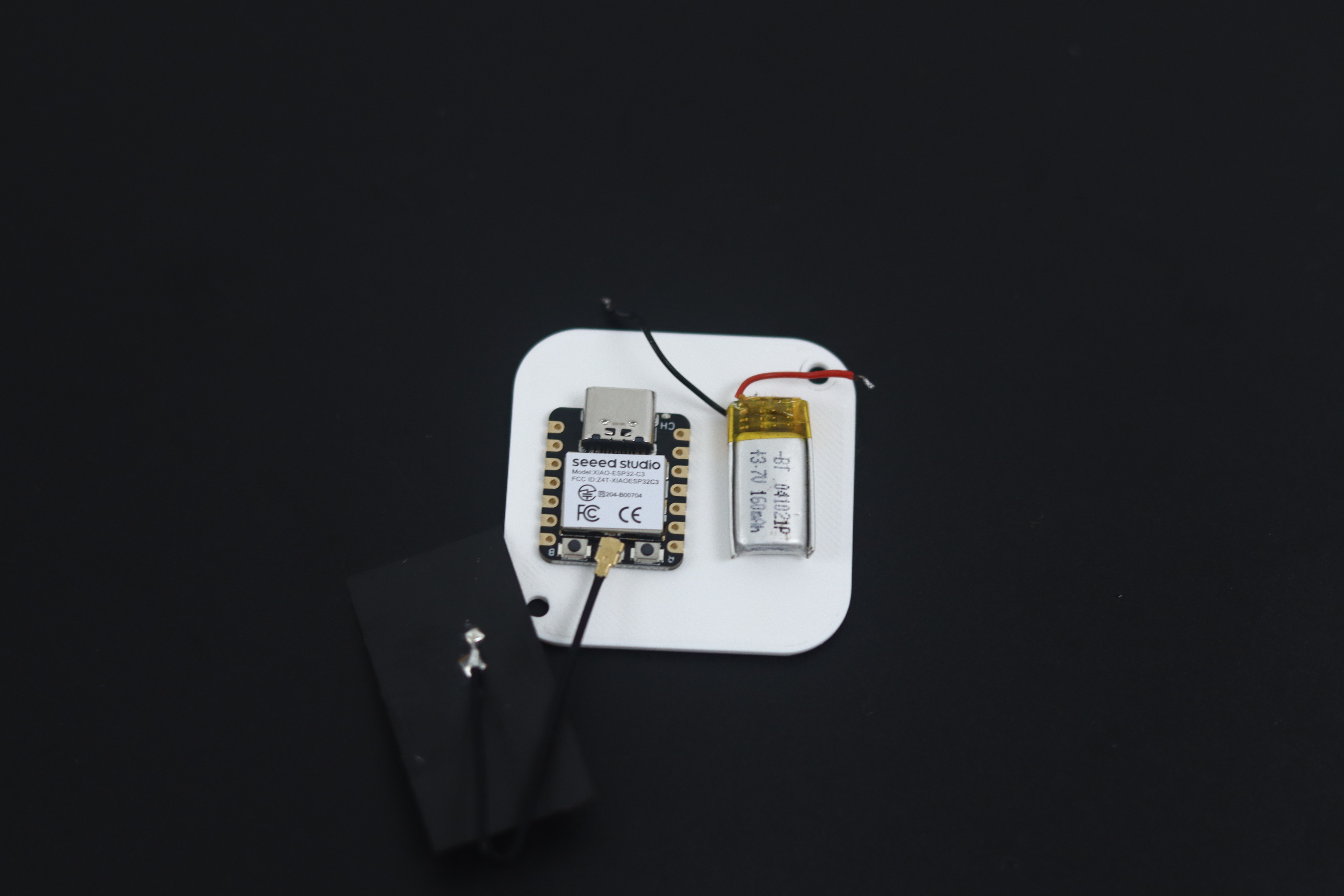
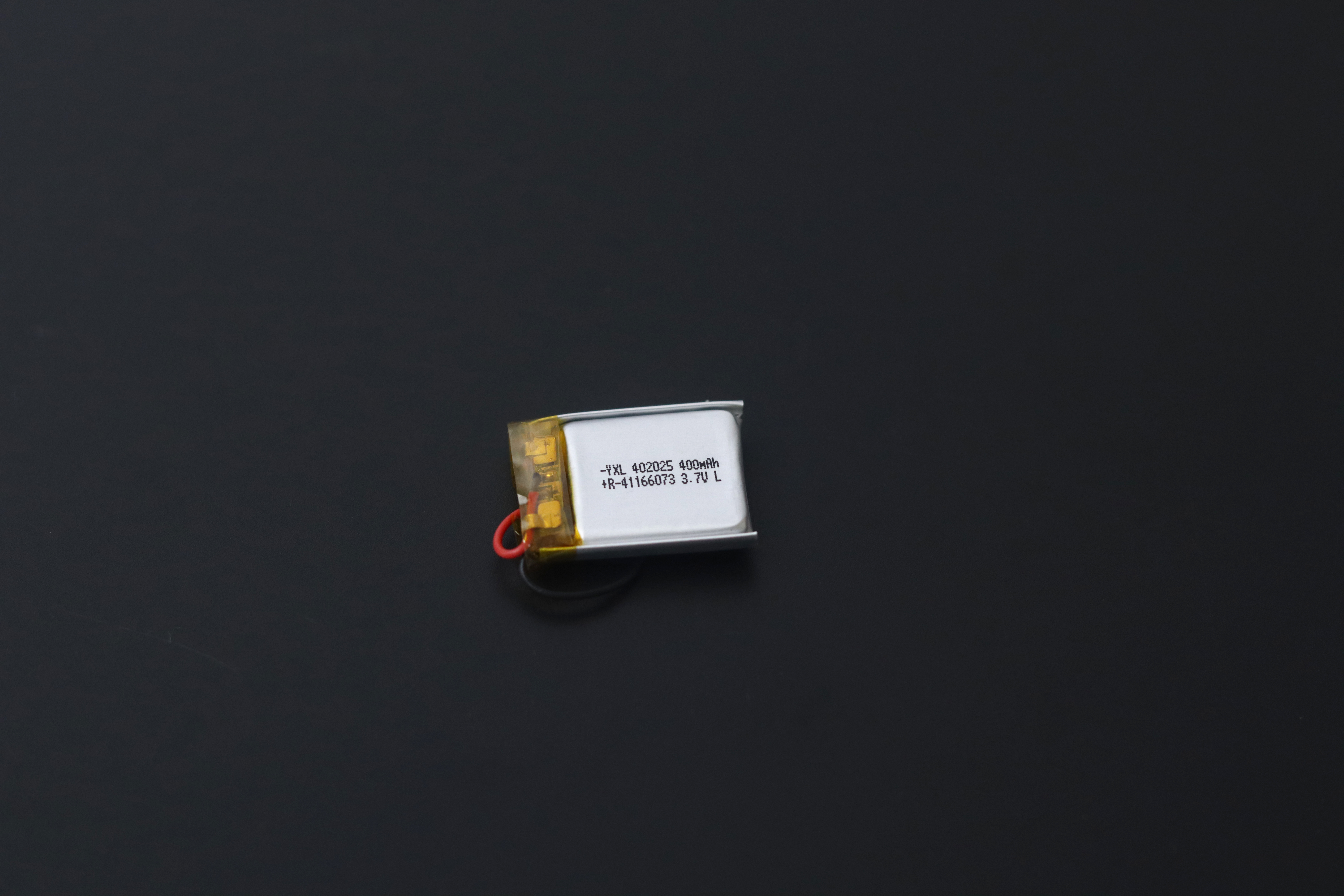
Due to its smaller size, we used a small battery with a capacity of 150 mah, and this is the design of the Node.
Firmware
On the node side, we have developed the firmware in such a way that the ESP32C3 will act as a BLE client and send the sensor data to the multiconnect BLE server. A sample code is shown below.
#include "BLEDevice.h"
//#include "BLEScan.h"

// The remote service we wish to connect to.
static BLEUUID serviceUUID("4fafc201-1fb5-459e-8fcc-c5c9c331914b");
// The characteristic of the remote service we are interested in.
static BLEUUID charUUID("beb5483e-36e1-4688-b7f5-ea07361b26a8");

static boolean doConnect = false;
static boolean connected = false;
static boolean doScan = false;
static BLERemoteCharacteristic* pRemoteCharacteristic;
static BLEAdvertisedDevice* myDevice;

int tempPin = 2;

static void notifyCallback(
  BLERemoteCharacteristic* pBLERemoteCharacteristic,
  uint8_t* pData,
  size_t length,
  bool isNotify) {
    Serial.print("Notify callback for characteristic ");
    Serial.print(pBLERemoteCharacteristic->getUUID().toString().c_str());
    Serial.print(" of data length ");
    Serial.println(length);
    Serial.print("data: ");
    Serial.write(pData, length);
    Serial.println();
}

class MyClientCallback : public BLEClientCallbacks {
  void onConnect(BLEClient* pclient) {
  }

  void onDisconnect(BLEClient* pclient) {
    connected = false;
    Serial.println("onDisconnect");
  }
};

bool connectToServer() {
    Serial.print("Forming a connection to ");
    Serial.println(myDevice->getAddress().toString().c_str());

    BLEClient*  pClient  = BLEDevice::createClient();
    Serial.println(" - Created client");

    pClient->setClientCallbacks(new MyClientCallback());

    // Connect to the remove BLE Server.
    pClient->connect(myDevice);  // if you pass BLEAdvertisedDevice instead of address, it will be recognized type of peer device address (public or private)
    Serial.println(" - Connected to server");
    pClient->setMTU(517); //set client to request maximum MTU from server (default is 23 otherwise)

    // Obtain a reference to the service we are after in the remote BLE server.
    BLERemoteService* pRemoteService = pClient->getService(serviceUUID);
    if (pRemoteService == nullptr) {
      Serial.print("Failed to find our service UUID: ");
      Serial.println(serviceUUID.toString().c_str());
      pClient->disconnect();
      return false;
    }
    Serial.println(" - Found our service");


    // Obtain a reference to the characteristic in the service of the remote BLE server.
    pRemoteCharacteristic = pRemoteService->getCharacteristic(charUUID);
    if (pRemoteCharacteristic == nullptr) {
      Serial.print("Failed to find our characteristic UUID: ");
      Serial.println(charUUID.toString().c_str());
      pClient->disconnect();
      return false;
    }
    Serial.println(" - Found our characteristic");

    // Read the value of the characteristic.
    if(pRemoteCharacteristic->canRead()) {
      std::string value = pRemoteCharacteristic->readValue();
      Serial.print("The characteristic value was: ");
      Serial.println(value.c_str());
    }

    if(pRemoteCharacteristic->canNotify())
      pRemoteCharacteristic->registerForNotify(notifyCallback);

    connected = true;
    return true;
}

class MyAdvertisedDeviceCallbacks: public BLEAdvertisedDeviceCallbacks {

  void onResult(BLEAdvertisedDevice advertisedDevice) {
    Serial.print("BLE Advertised Device found: ");
    Serial.println(advertisedDevice.toString().c_str());


    if (advertisedDevice.haveServiceUUID() && advertisedDevice.isAdvertisingService(serviceUUID)) {

      BLEDevice::getScan()->stop();
      myDevice = new BLEAdvertisedDevice(advertisedDevice);
      doConnect = true;
      doScan = true;

    }
  }
};


void setup() {
  pinMode(tempPin, INPUT);
  Serial.begin(115200);
  Serial.println("Starting Arduino BLE Client application...");
  BLEDevice::init("Client");


  BLEScan* pBLEScan = BLEDevice::getScan();
  pBLEScan->setAdvertisedDeviceCallbacks(new MyAdvertisedDeviceCallbacks());
  pBLEScan->setInterval(1349);
  pBLEScan->setWindow(449);
  pBLEScan->setActiveScan(true);
  pBLEScan->start(5, false);
}

void loop() {

  if (doConnect == true) {
    if (connectToServer()) {
      Serial.println("We are now connected to the BLE Server.");
    } else {
      Serial.println("We have failed to connect to the server; there is nothin more we will do.");
    }
    doConnect = false;
  }

  float temp = analogRead(tempPin)*0.1039;

  if (connected) {
    String newValue = "TEMP:" + String(temp);
    Serial.println(newValue);


    pRemoteCharacteristic->writeValue(newValue.c_str(), newValue.length());
  }else if(doScan){
    BLEDevice::getScan()->start(0);
  }

  delay(1000); // Delay a second between loops.
}
Here are the sample nodes.
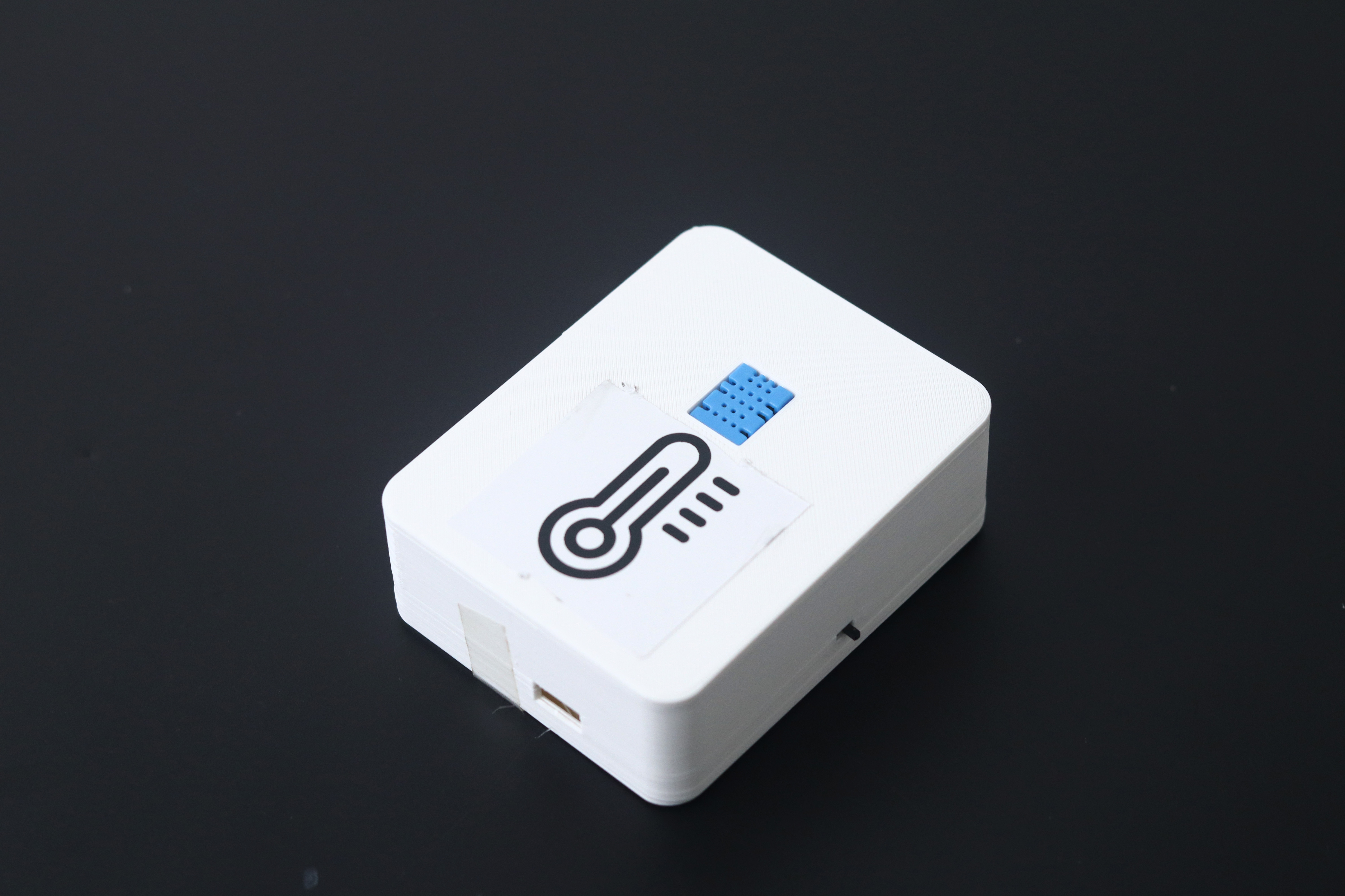
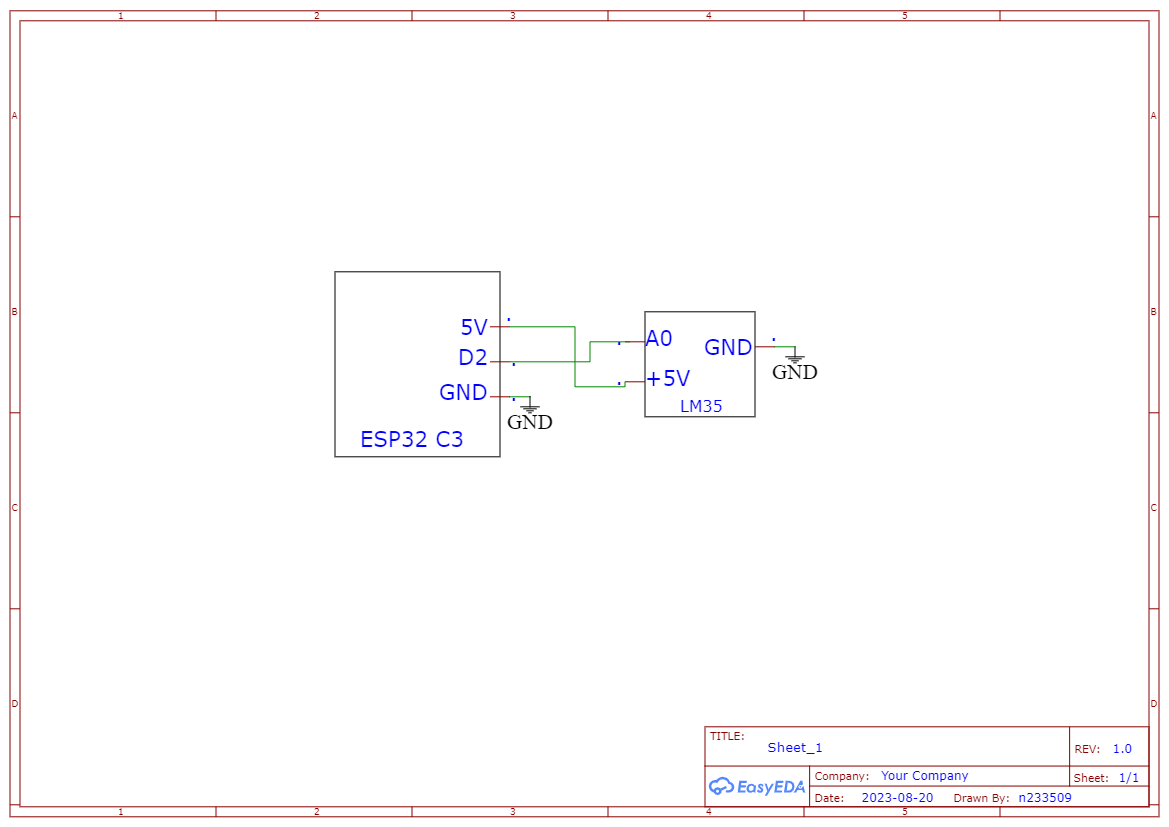
1. Temperature Node
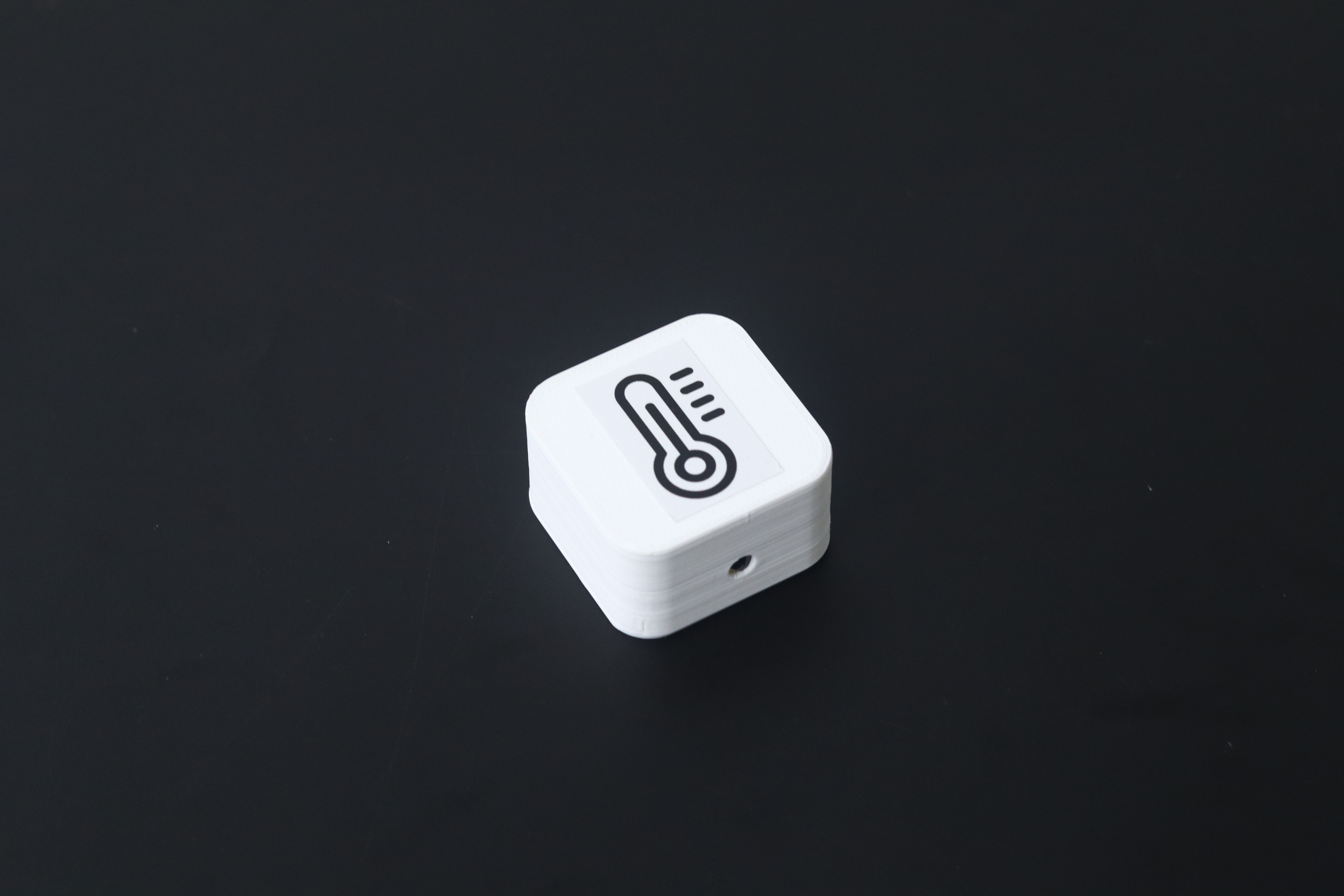
This node is based on the LM35 sensor. It is used to send the temperature value to the cloud.
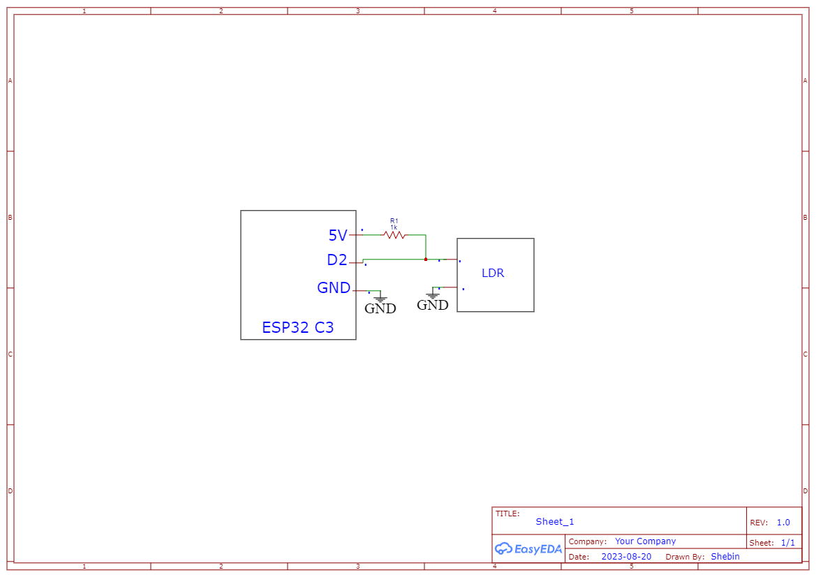
2. Light Intensity Node
This node is based on the LDR. It will update the light intensity to the cloud.
Conclusion
Modular IoT Kit is not just a product; it's a paradigm shift. Its user-first approach tears down the complexity barriers, making IoT accessible to all, regardless of technical prowess.
The dashboard serves as a digital canvas, where data comes alive through widgets you can effortlessly add, resize, and arrange. The dashboard's creation relies on familiar web technologies—HTML, CSS, JS—enhanced by the Interact JS library for seamless interaction. MQTT JS ensures real-time connectivity, cementing the dashboard's role as a control center.
Enter the BLE-enabled variant, a marvel in efficiency. With Bluetooth Low Energy, nodes thrive on minimal power, expanding their lifespan remarkably. The gateway's architecture orchestrates intricate data flow, connecting BLE clients to MQTT brokers. It's a symphony of innovation, scaling connections effortlessly.
Looking ahead, the Modular IoT Kit redefines possibility. It's more than technology; it's empowerment. As everyday individuals harness the potential of IoT, industries are poised for transformation. This democratization of innovation is set to revolutionize how we live and work, ushering in an era where connected devices shape a smarter, more efficient world.
In essence, the Modular IoT Kit isn't just shaping IoT; it's shaping the future—yours, mine, and everyone's. It's an invitation to create, innovate, and connect, marking a turning point where technology bows to simplicity and everyone holds the reins of progress. Welcome to the revolution.
-
Code

-
Schematics
-
BOM