
WIZnet IoT World-Clock
The IoT World-Clock showcases global times with precision using synced stepper motor hands and W5300 Ethernet-powered SNTP.
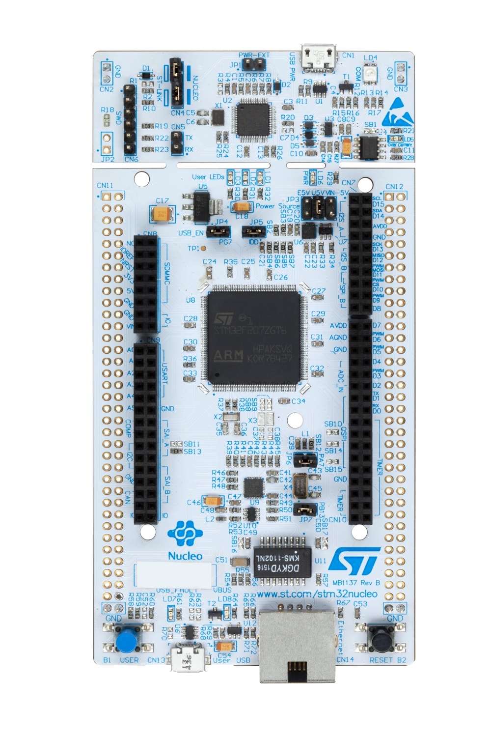
ST - NUCLEO-F429ZI
x 1
This project uses NUCLEO-F722ZE as an alternative to the NUCLEO-F429ZI
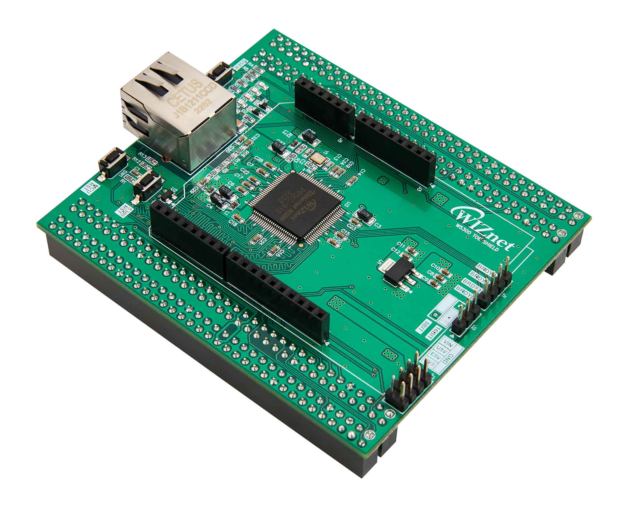
WIZnet - W5300-TOE-Shield
x 1
Overview
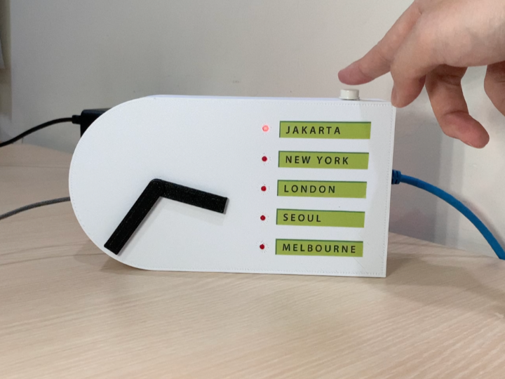
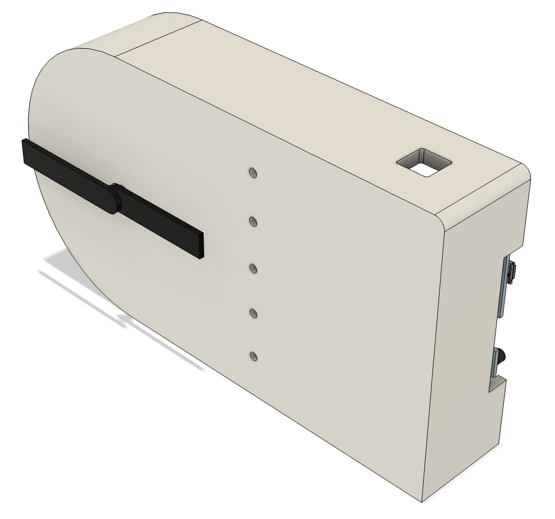
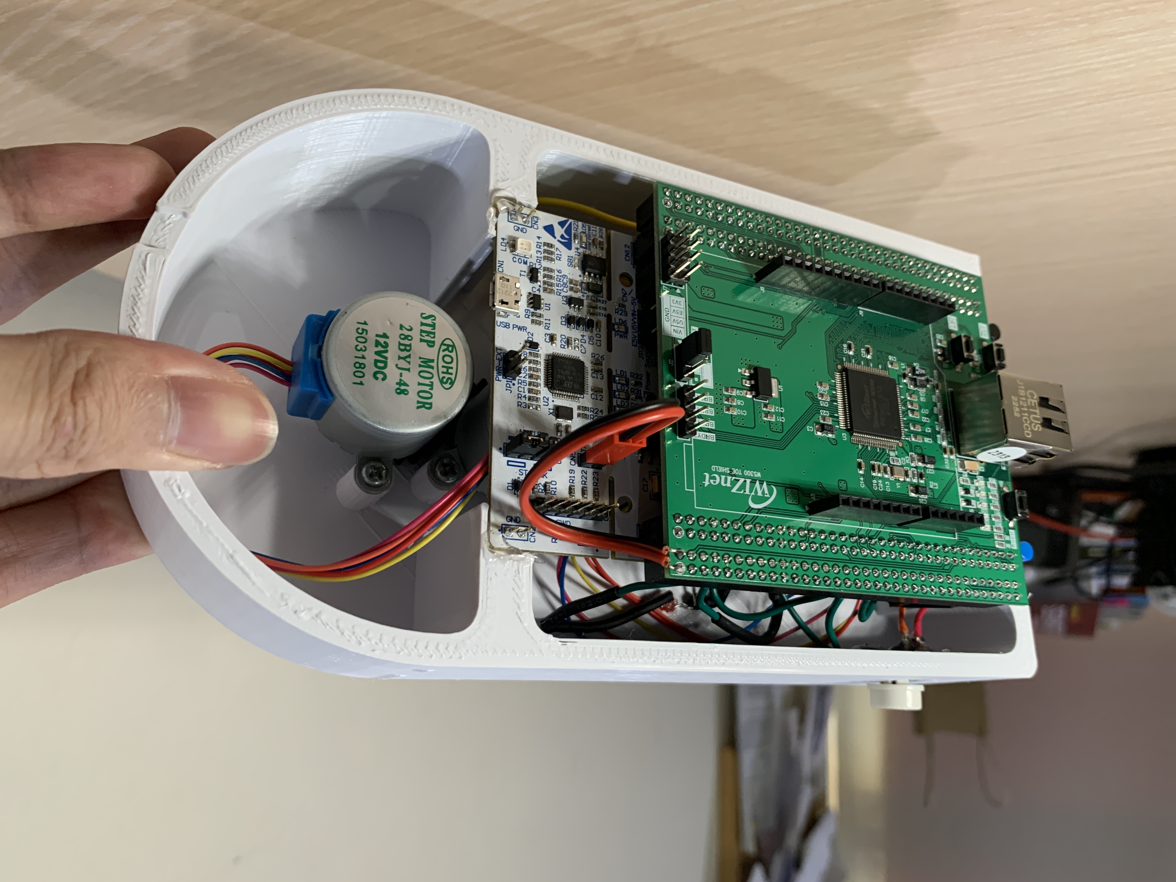
The WIZnet IoT World-Clock uses stepper motor-controlled hour and minute hands with internet connectivity via an embedded ethernet chip. Whether you are in a multinational office space, a global conference center, or at home preparing for international calls, this IoT World-Clock serves as a functional solution for effortlessly tracking time zones. Its real-time synchronization with cities' time via SNTP ensures accuracy, while the synchronized movement of the hour and minute hands adds a visual spectacle to the experience.
The WIZnet IoT World Clock takes advantage of the powerful W5300 network controller chip to offload the TCP/IP controls using the hardwired TCP/IP stack, this means we have more room for CPU and memory on our main microcontroller (STM32 NUCLEO-F722ZE) to use it for controlling the stepper motors.
The program takes the time from SNTP (Simple Network Time Protocol) servers and use that data is used to determine how much angle (or more accurately how many steps) the motors need to turn to display the current time of our desired time zones.
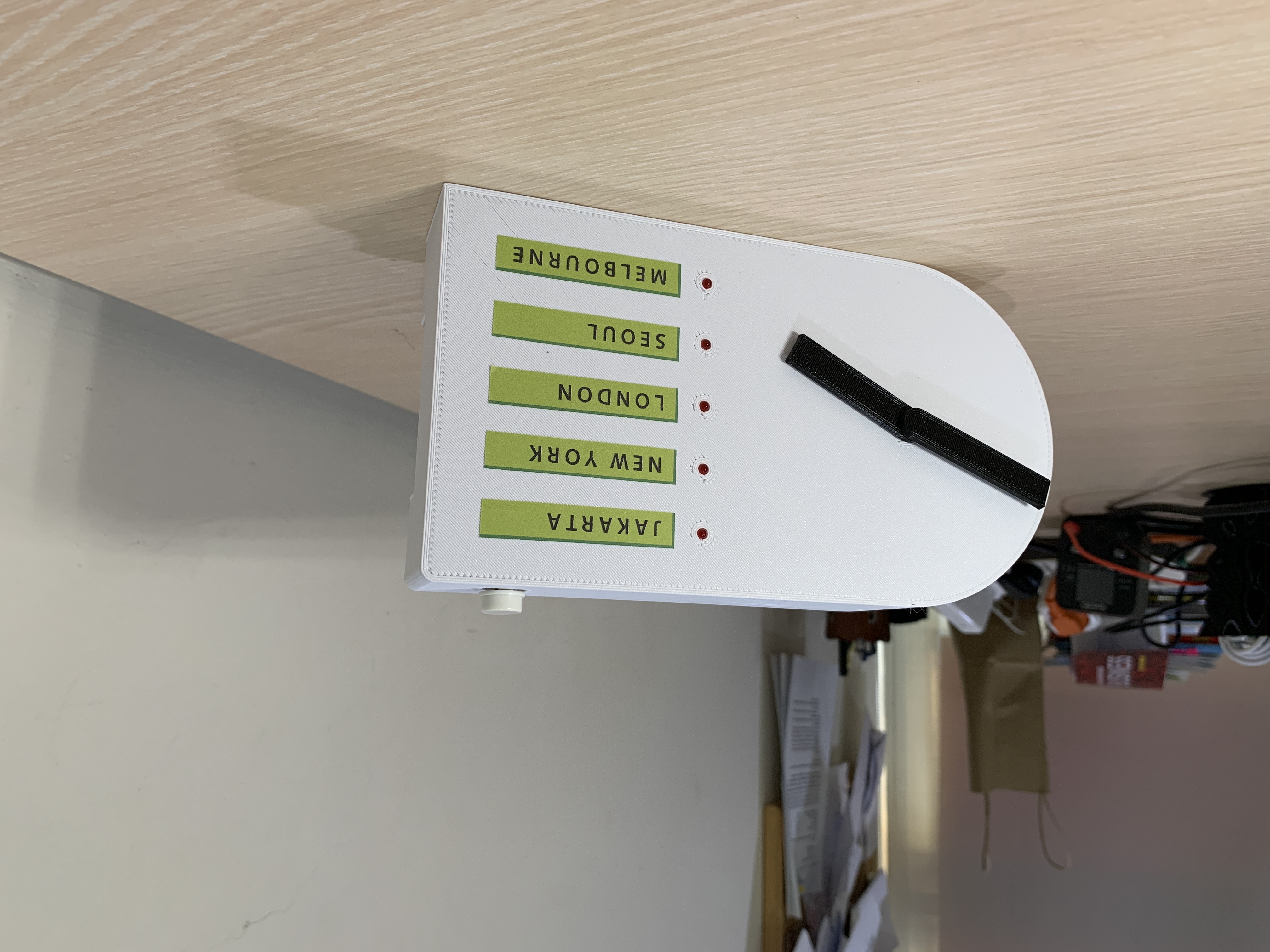
The WIZnet Iot World Clock has a button on the top right corner that can be used to toggle between five cities/time zones. The 3mm LED indicates which city/time zone is currently selected.
Parts:
1 x W5300-TOE-SHIELD
1 x ST-NUCLEO-F722ZE (or alternative NUCLEO-144 boards)
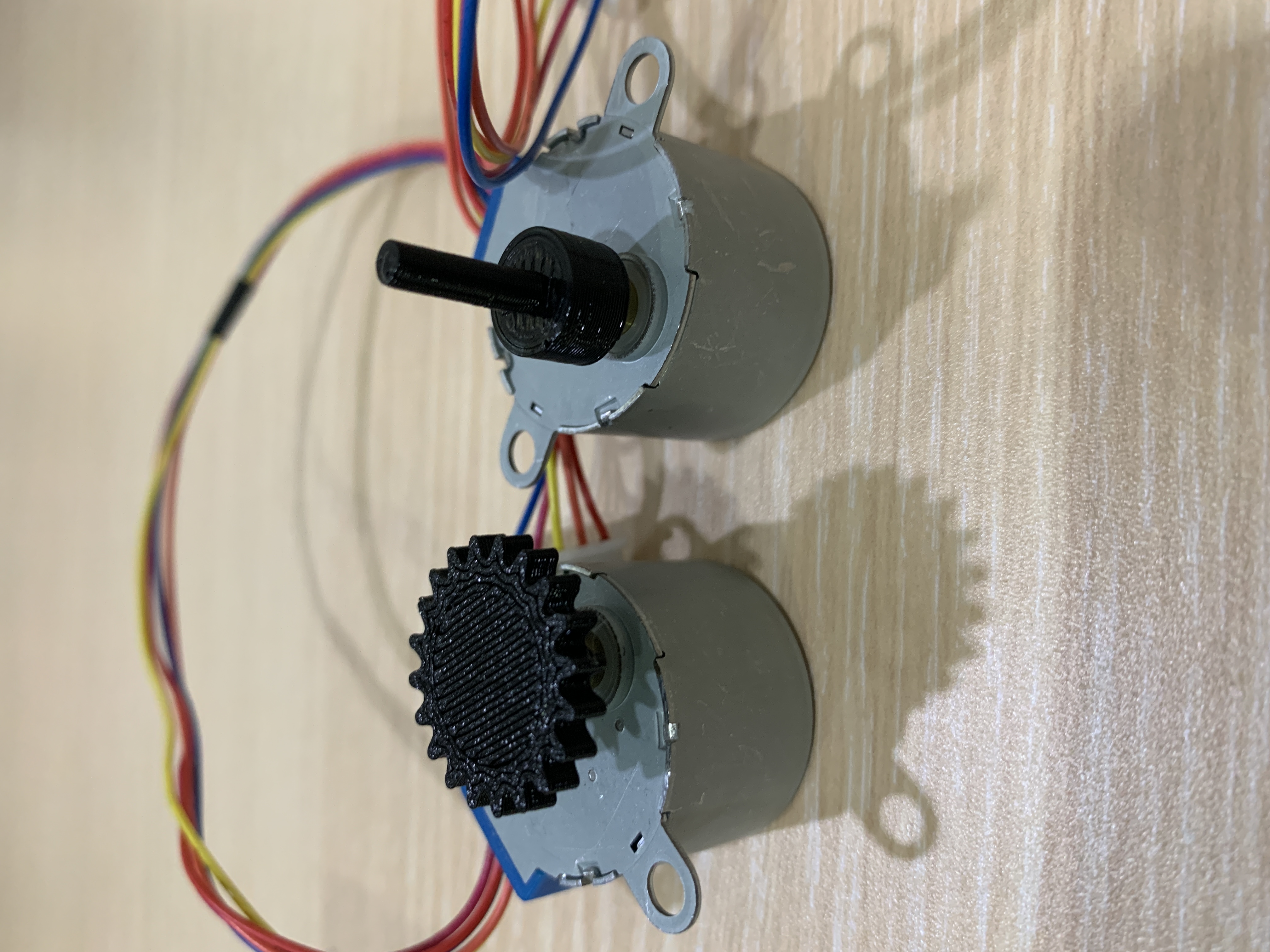
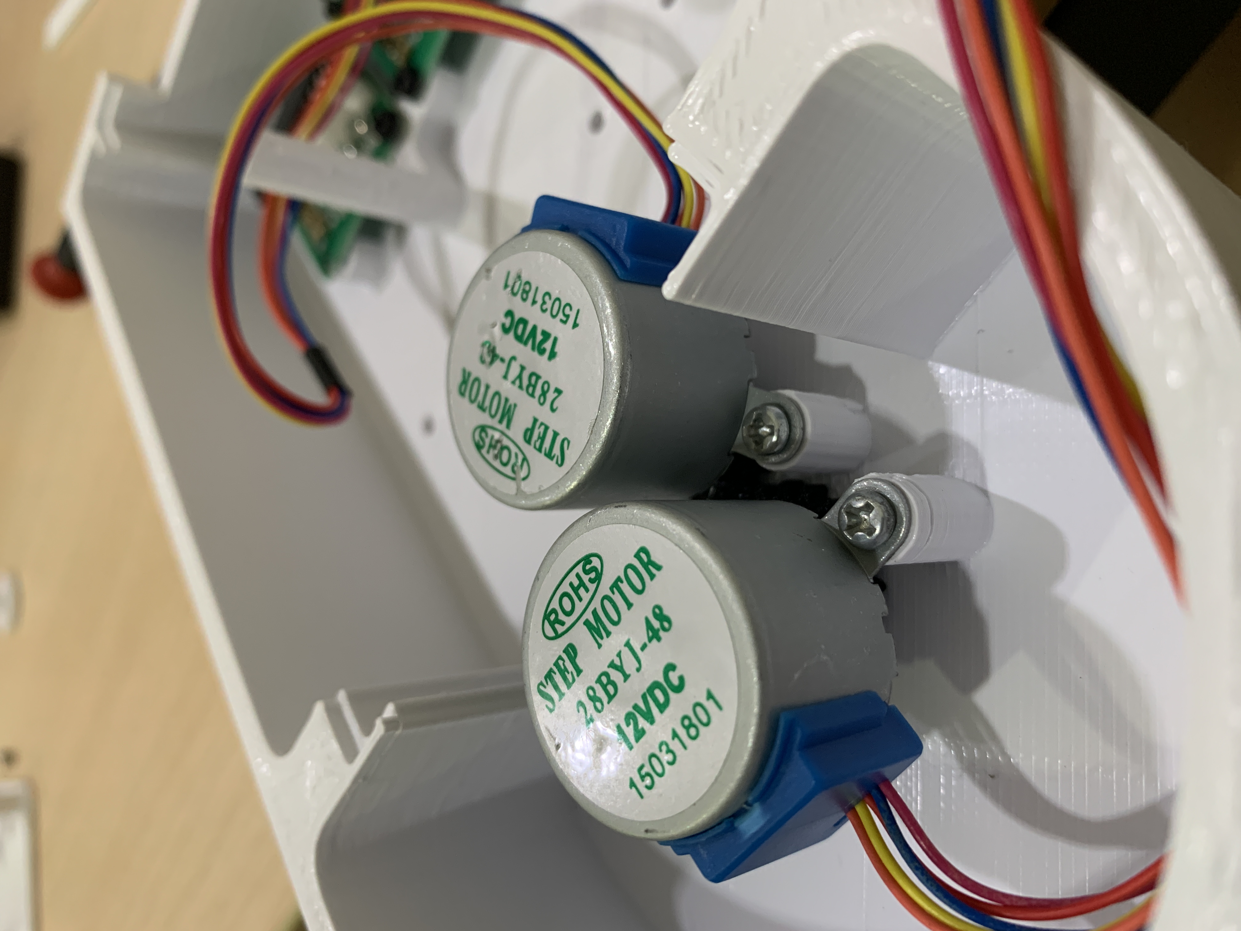
2 x 28BYJ48 stepper motor
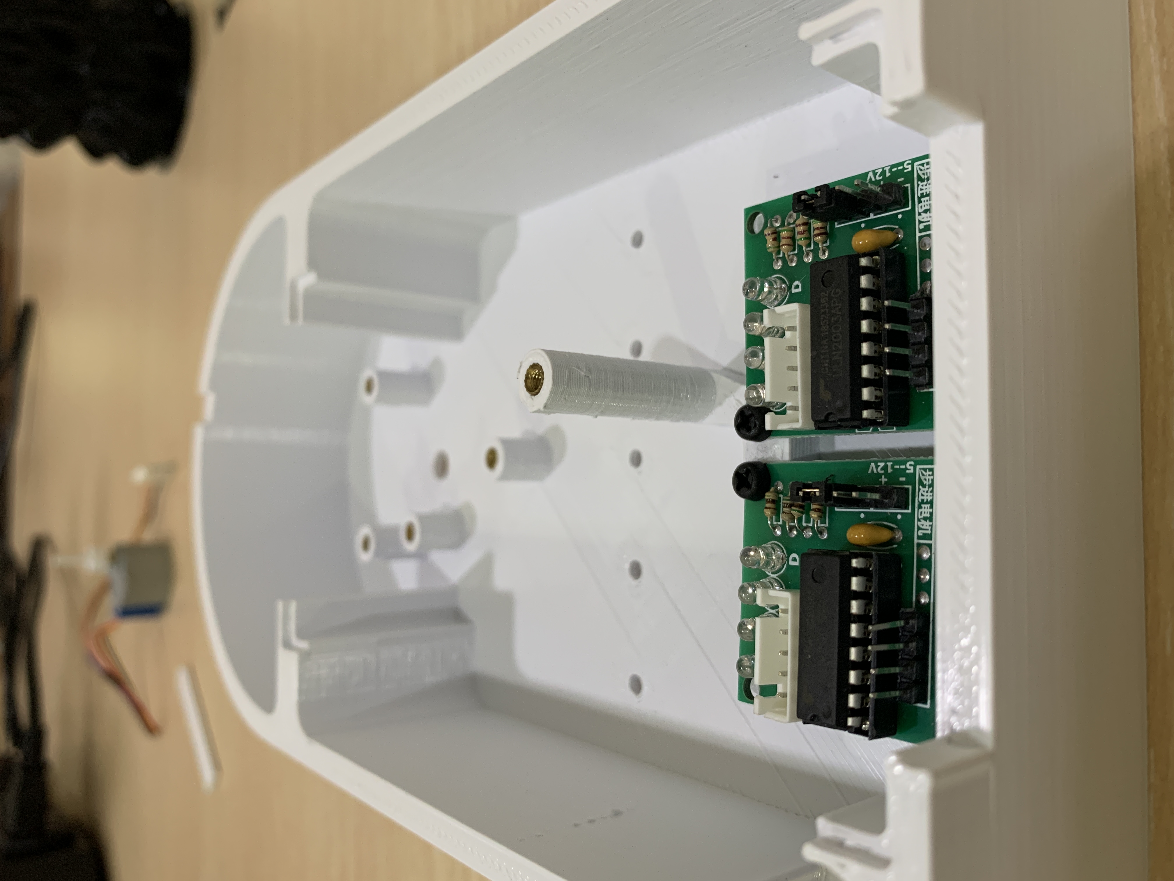
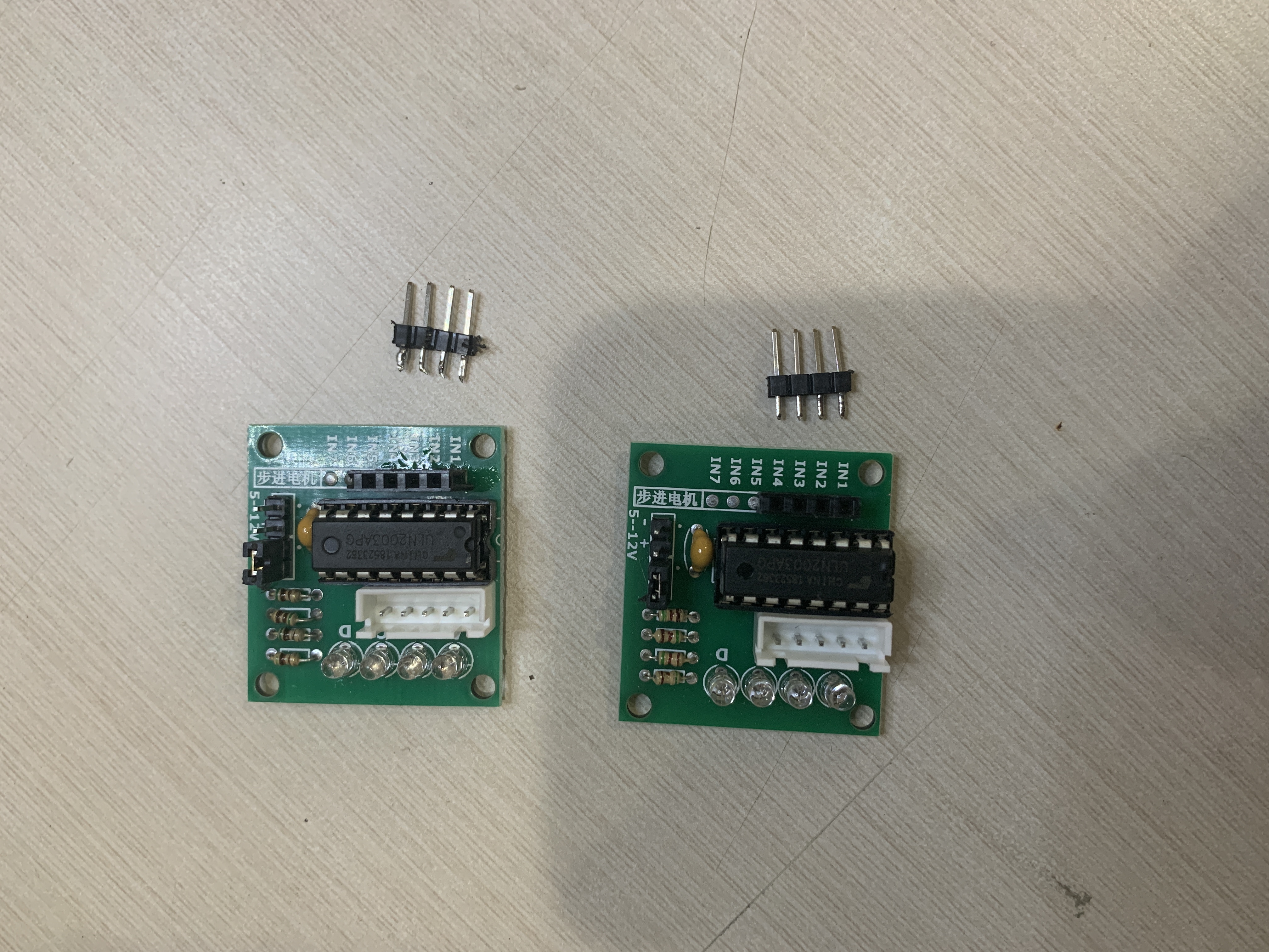
2 x ULN2003a driver
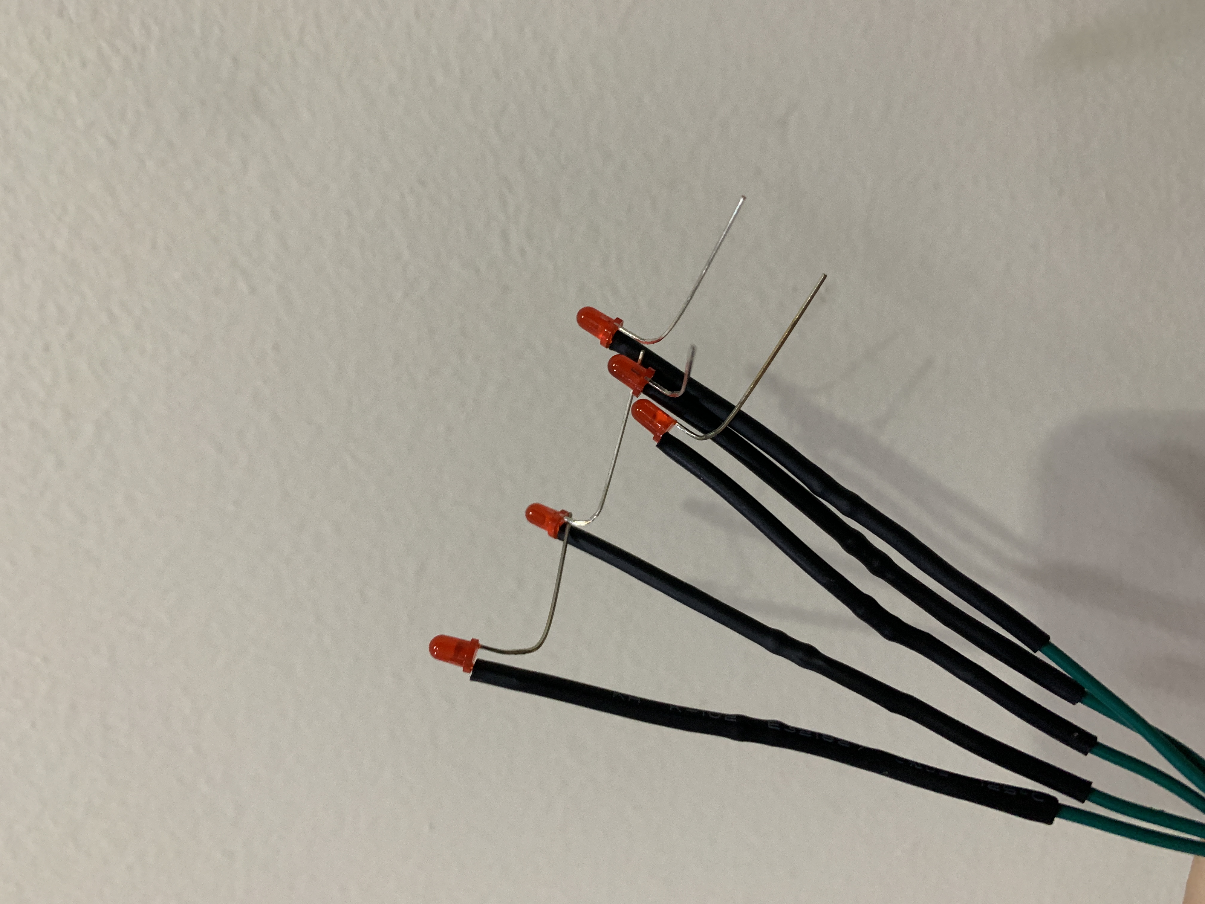
5 x 3mm LED
5 x 220 Ohm resistor
1 x 12mm button
1 x spool of 22-AWG wires
1 x set of jumper cables
1x 2m heat-shrink tube
Tools:
- Soldering iron
- 3D printer
- Cutting Plier
Software:
- STM32Cube IDE
- Terra Term (or any serial monitor)
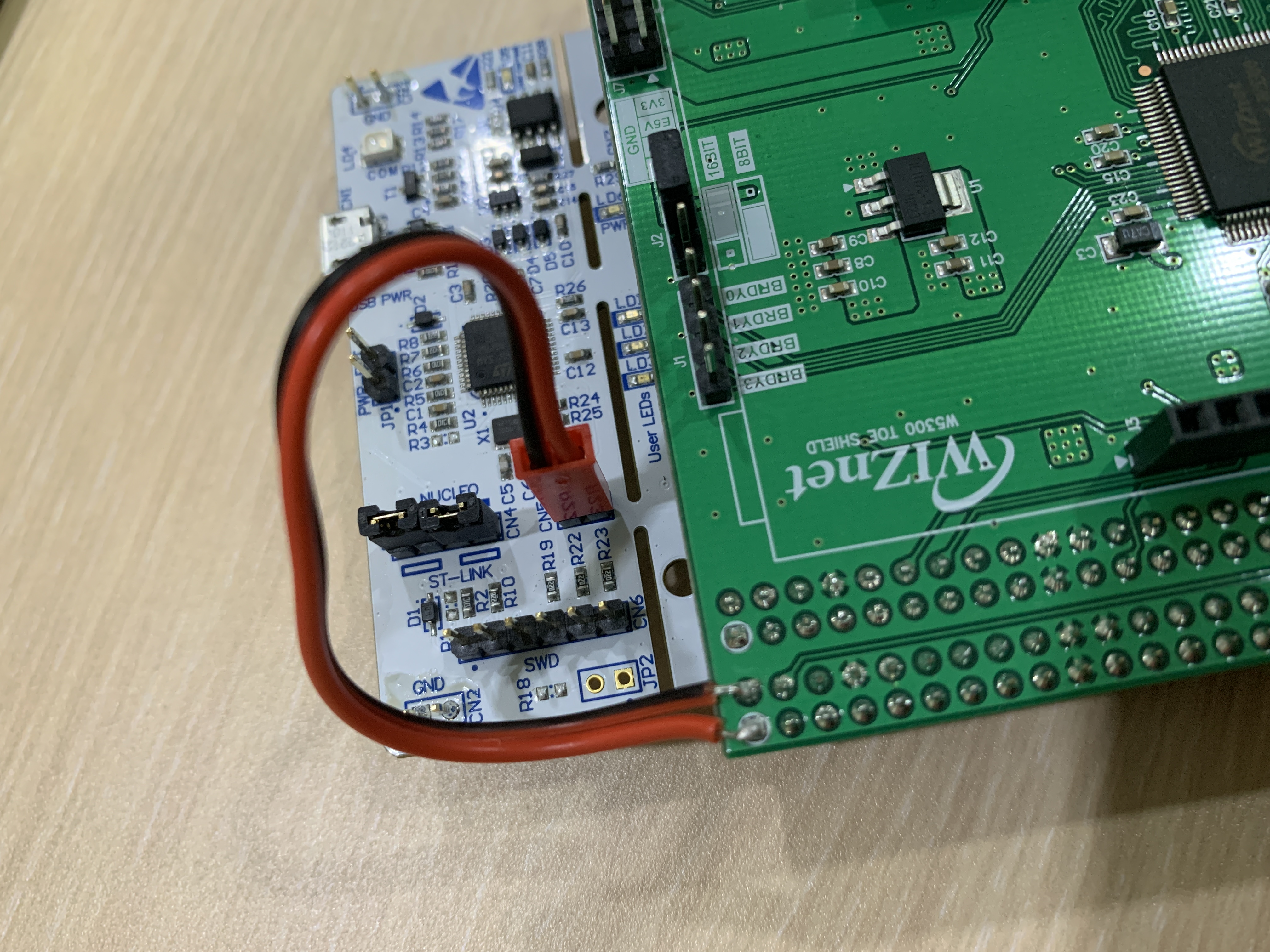
Step 1: Hardware preparation
The Nucleo Board comes with a built-in ST-LINK, but it uses overlapping pins with the FMC (Flexible Memory Controller) data pin to control the W5300. In order to solve this issue you will need to remove SB5 and SB6 from the Nucleo Board and use jumper wires to connect the PC10 and PC11 pins from the W5300 TOE Shield to the TX and RX on the ST-LINK.
You can check the getting started section on the official W5300-TOE-C documentation for more information.
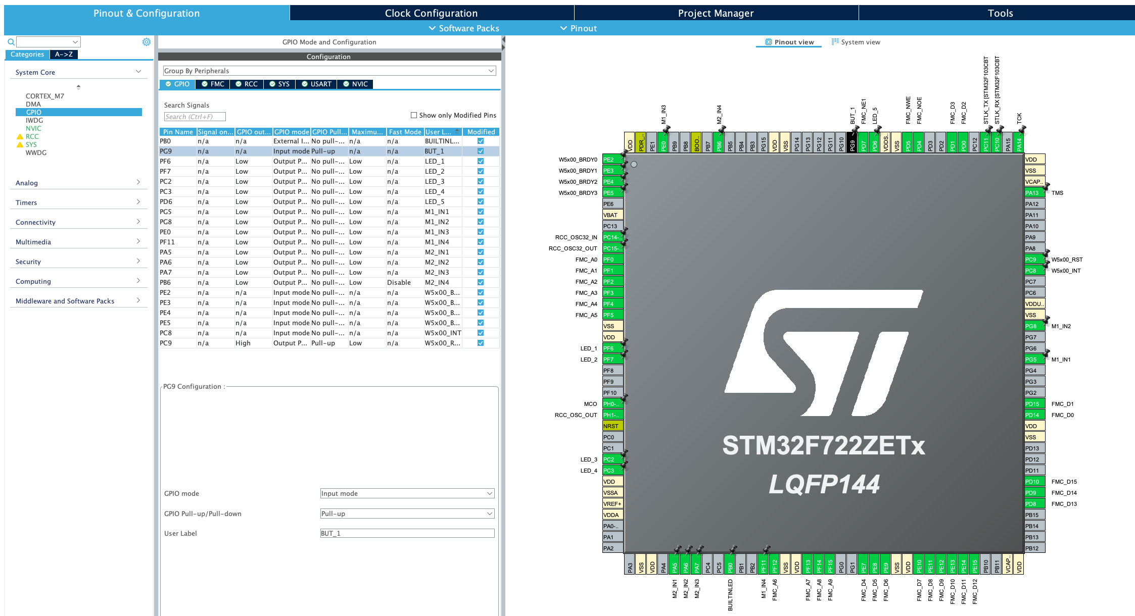
Step 2: Setup your IDE and hardware configuration (.ioc)
We can use the .ioc from the official W5300-TOE-C repository as a starting point. The .ioc file you’ll find there has pre-configured FMC pins and has already changed the ST-LINK TX and RX pins from PD8 and PD9 to PC10 and PC11.
The additional pins that we need to allocate for this project are as follows:
LED_1 = PF6 (Output)
LED_2 = PF7 (Output)
LED_3 = PC2 (Output)
LED_4 = PC3 (Output)
LED_5 = PD6 (Output)
BUT_1 = PG9 (Input Pull-Up)
M1_IN1 = PG5
M1_IN2 = PG8
M1_IN3 = PE0
M1_IN4 = PF11
M2_IN1 = PA5
M2_IN2 = PA6
M2_IN3 = PA7
M2_IN4 = PB6
Once the GPIOs are all set, add TIMER TIM1 as follows:
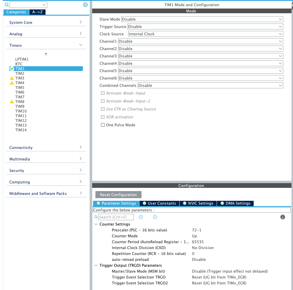
Now save this configuration and it will generate additional code in the main.c file.
Step 3: Configure IP and connect to the SNTP server
Configure your IP address and Gateway in the main.c file. Here is an example:
  wiz_NetInfo net_info =
      {
          .mac = {0x00, 0x08, 0xDC, 0x12, 0x34, 0x56}, // MAC address
          .ip = {192, 168, 0, 13},                     // IP address
          .sn = {255, 255, 255, 0},                  // Subnet Mask
          .gw = {192, 168, 0, 1},                     // Gateway
          .dns = {8, 8, 8, 8},                            // DNS server
#ifdef APP_DHCP
          .dhcp = NETINFO_DHCP              // Dynamic IP
#else
          .dhcp = NETINFO_STATIC            // Static IP
#endif
      };
Let's use one of the examples. Choose the SNTP example and try to connect to the SNTP server. Upload the code, if everything works well you can see something like this in your serial monitor.
Current time : 2023-8-19, 16:23:31You can try changing the TIMEZONE number and see what happens.
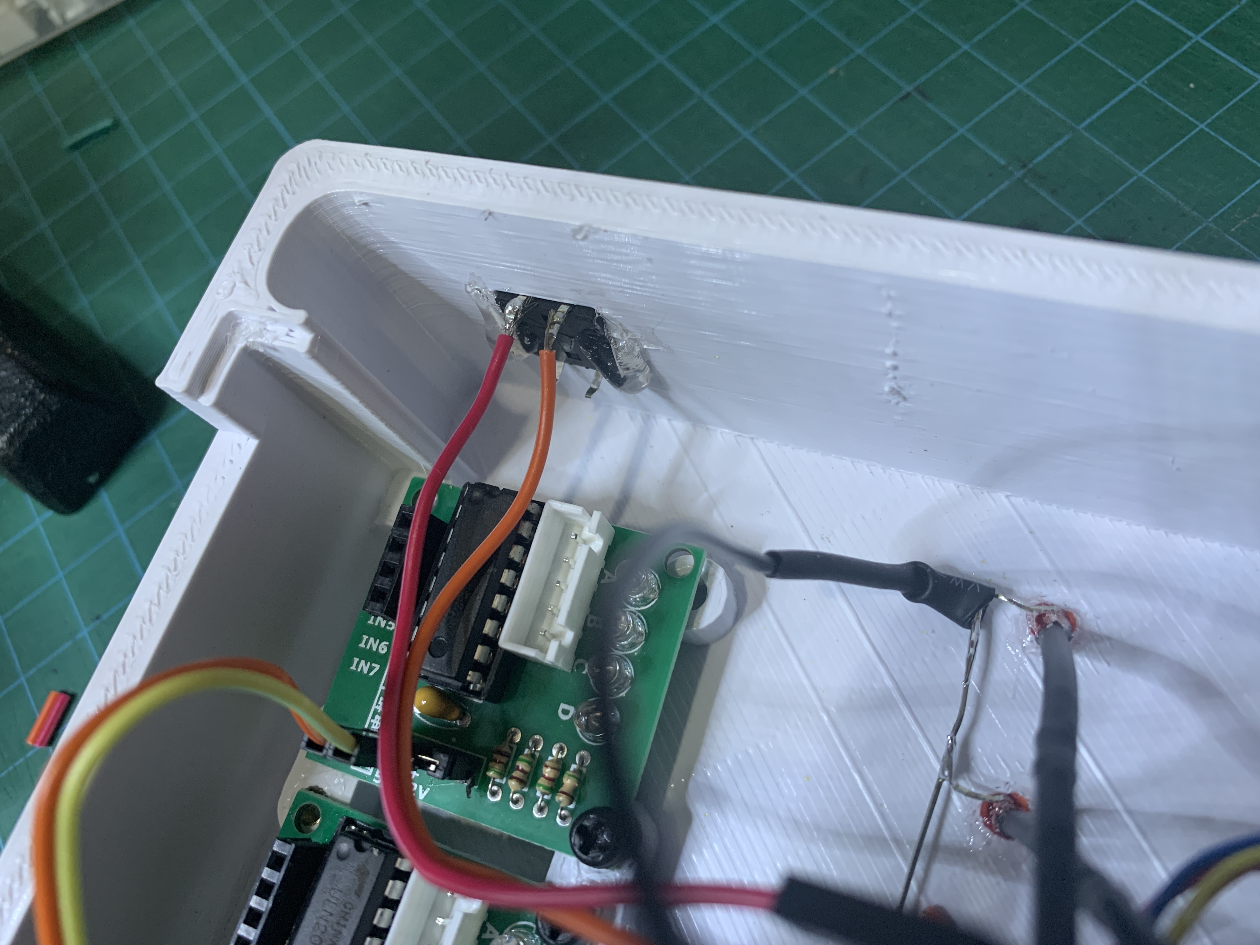
Step 4: Print the hardware and assemble the clock
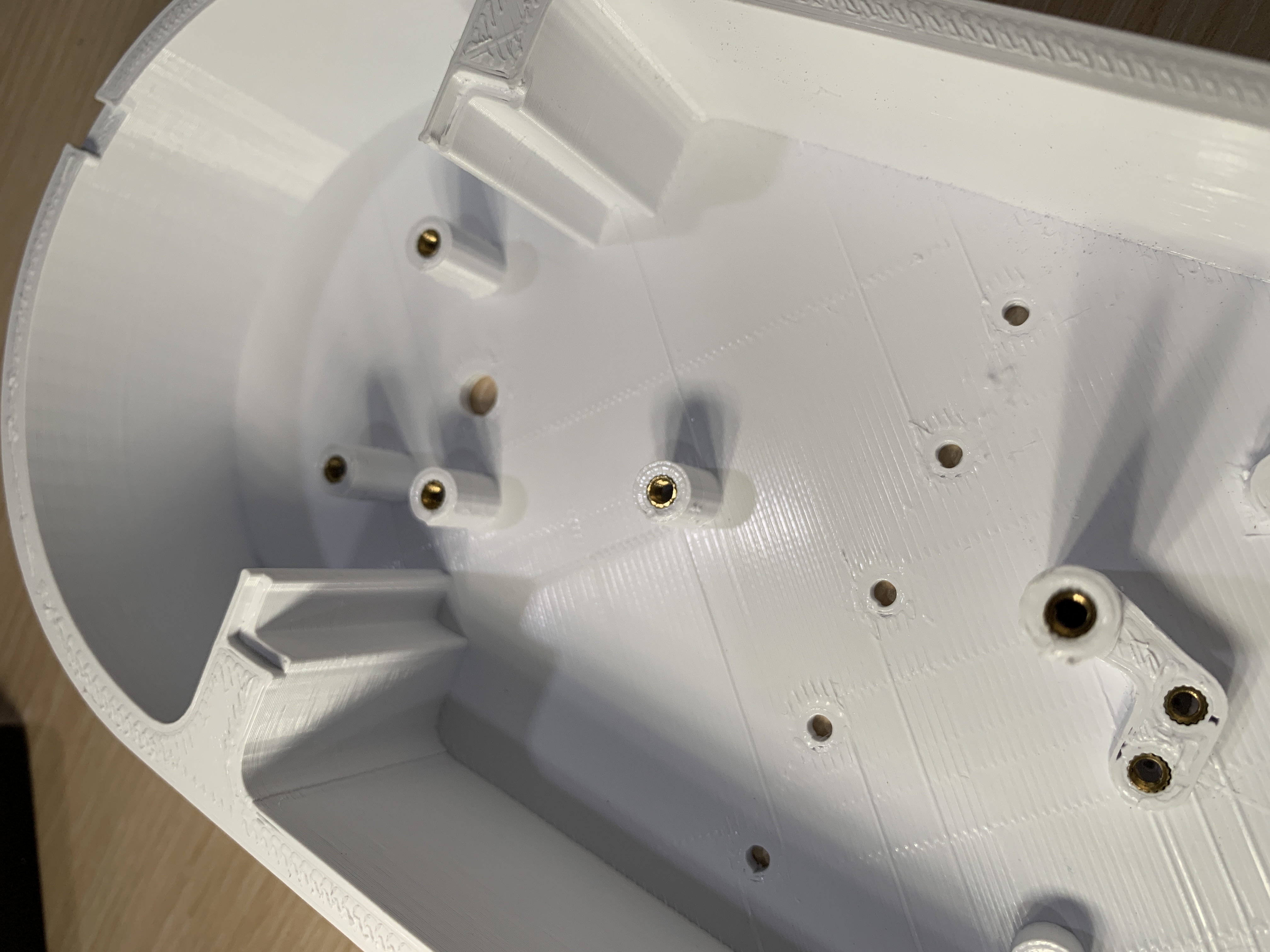
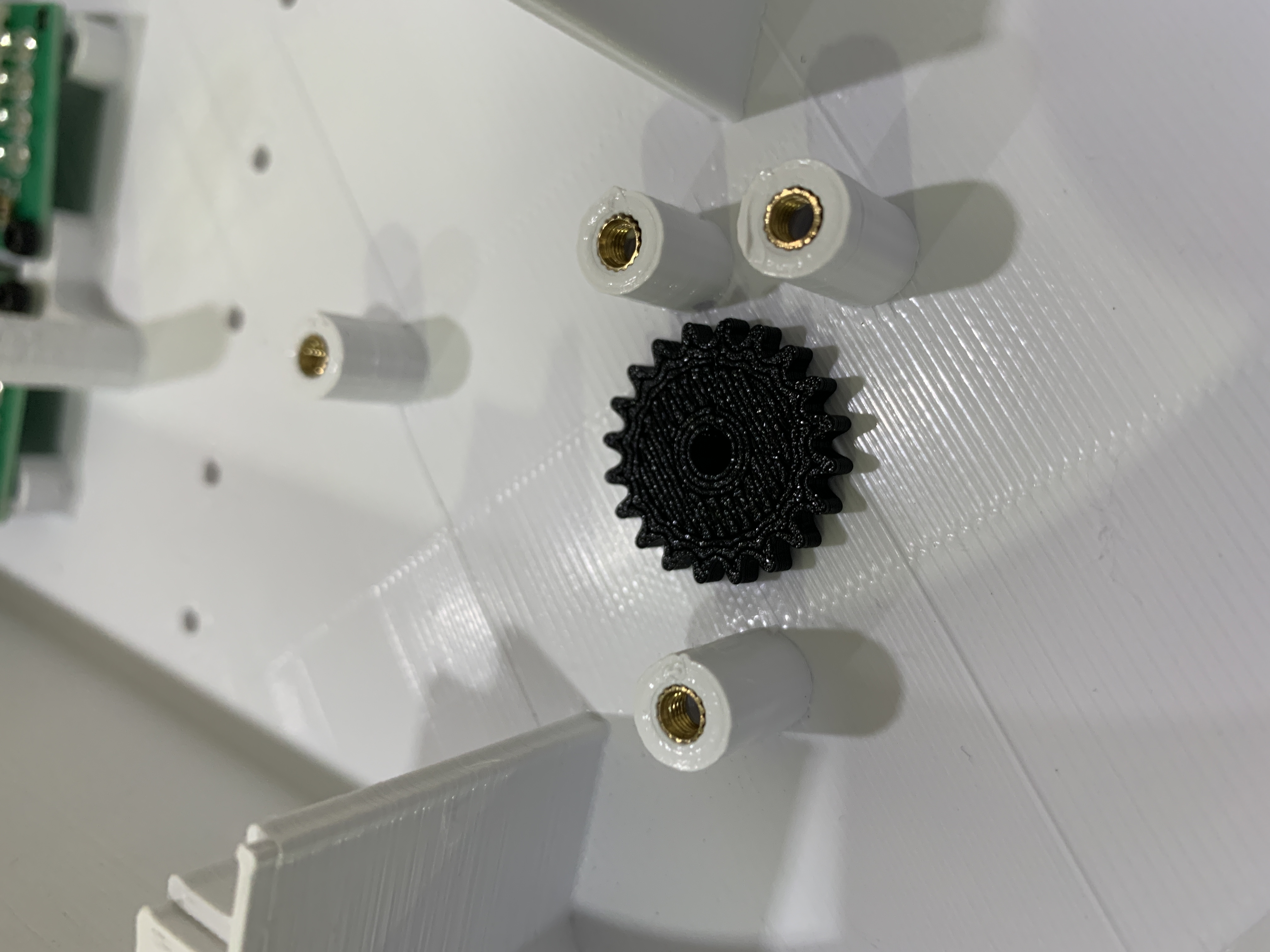
All the design files are included in the DOCUMENTS section of this project page. I use PLA+ with 15% Gyroid infill and no support for all the prints in this project.
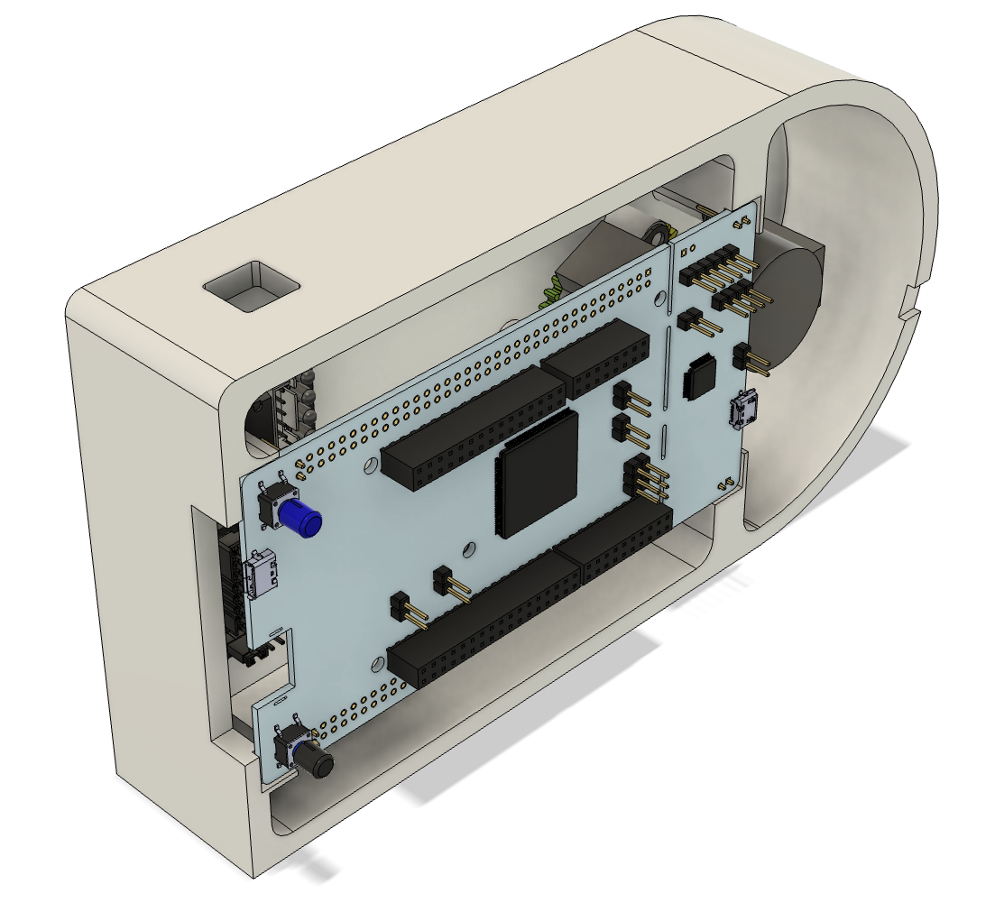
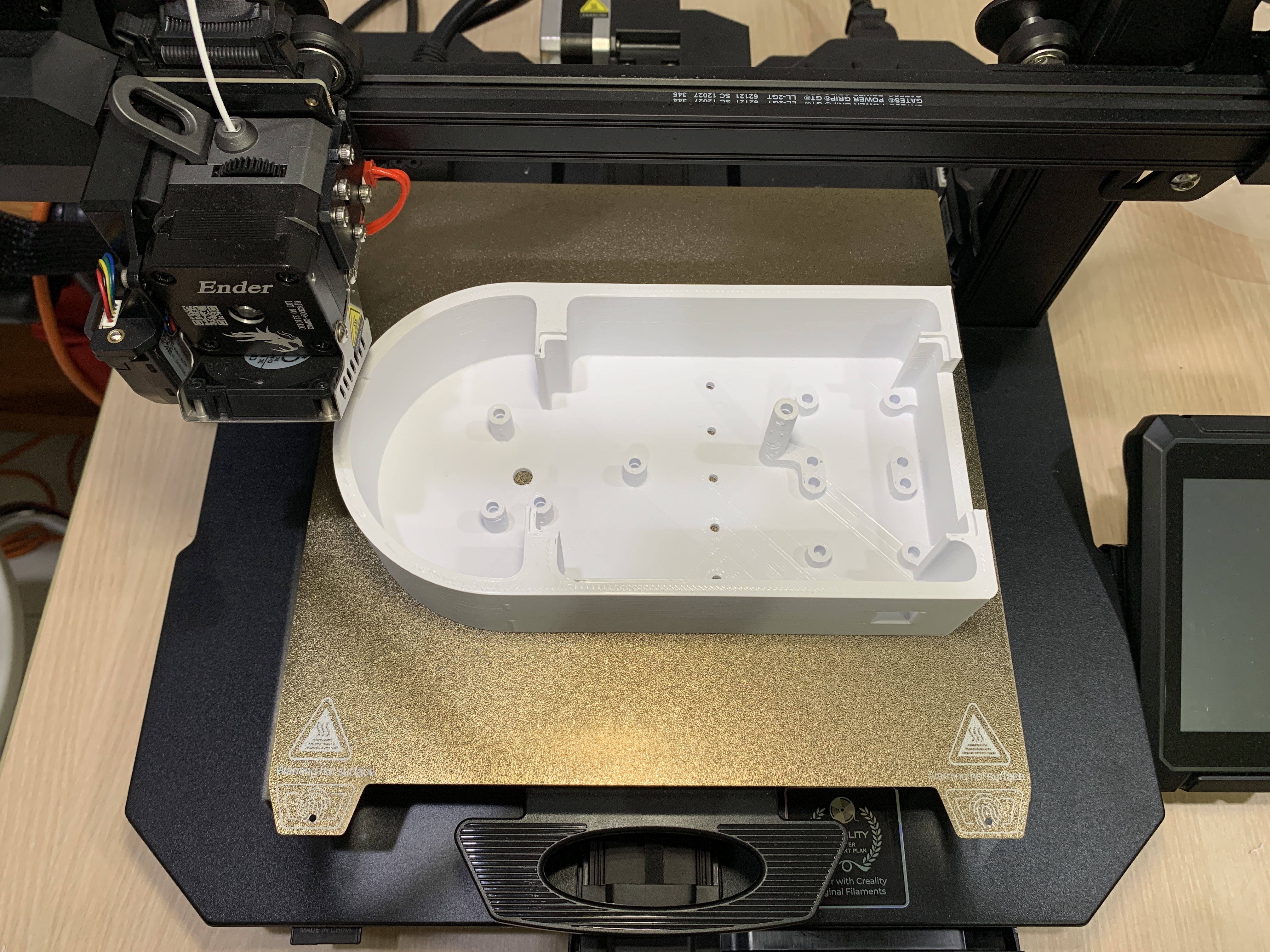
Add M3 threaded inserts using a soldering iron.
Attach hour gear mount and minute mount to the motors.
Solder 220 Ohm resistor to the Anode of the 3mm LEDs.
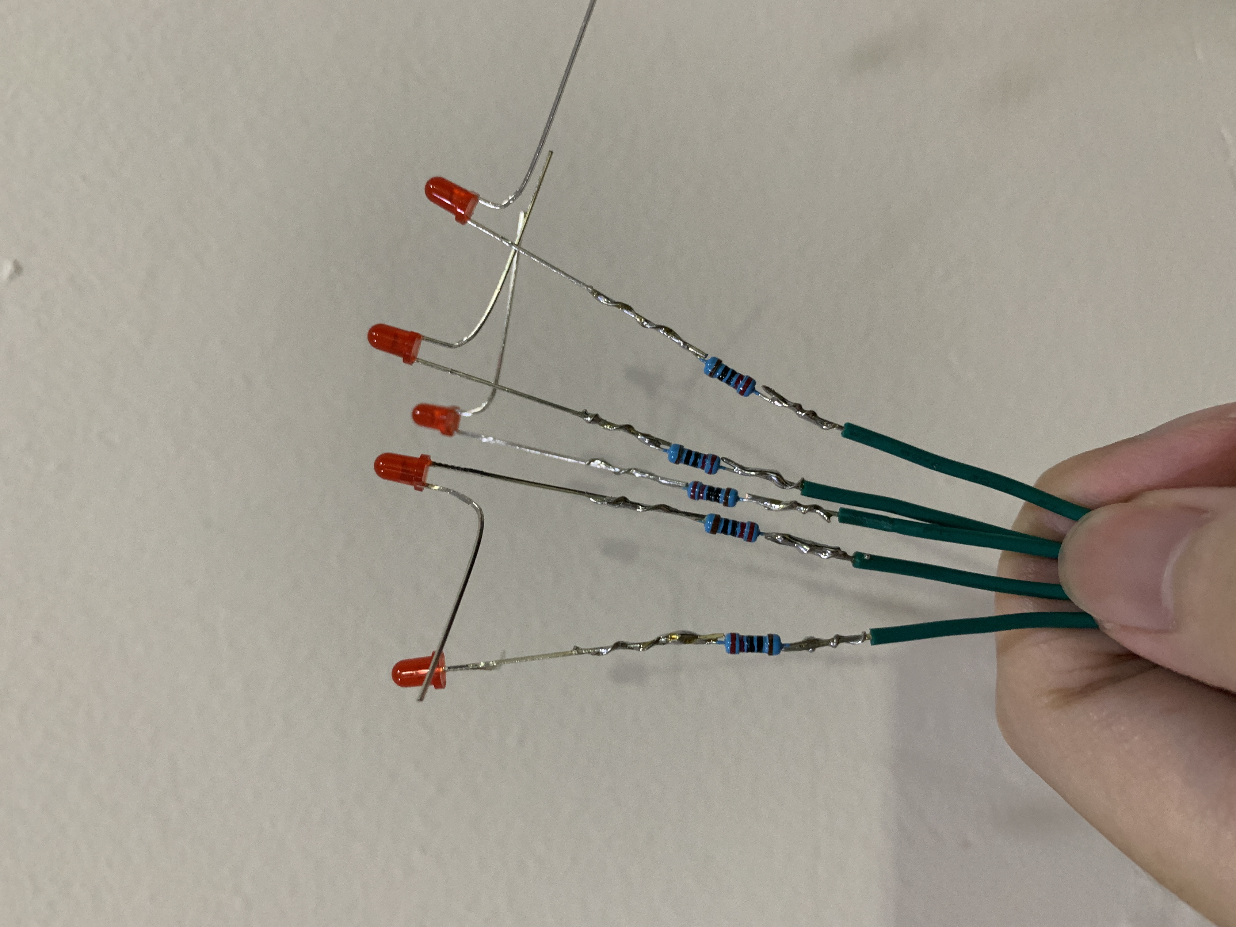
Use heat-shrink to cover the exposed wires.
Change male header pins to female header pins (optional). This step can be useful if you want to use a single core 22AWG wire so you can plug it directly.
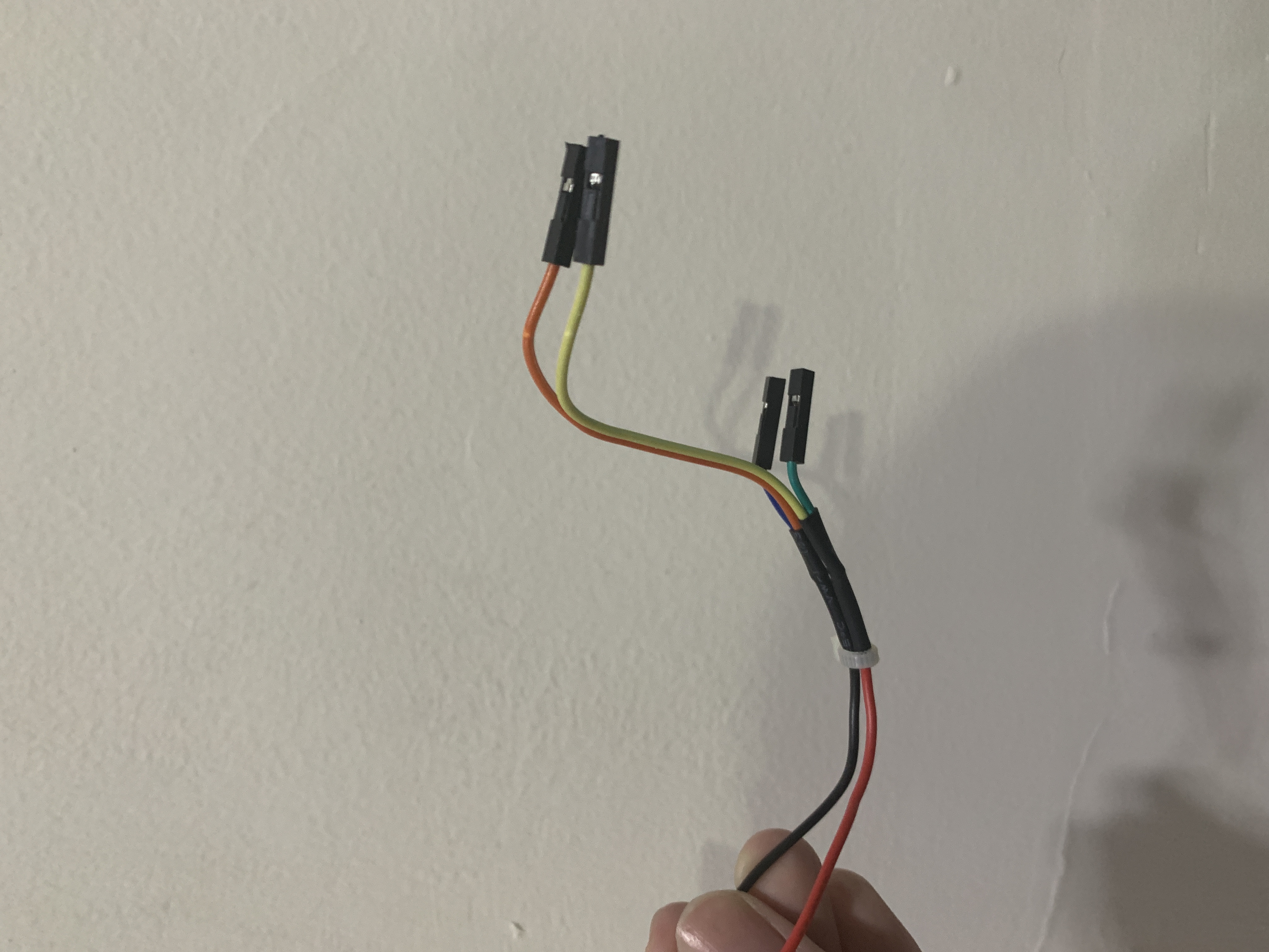
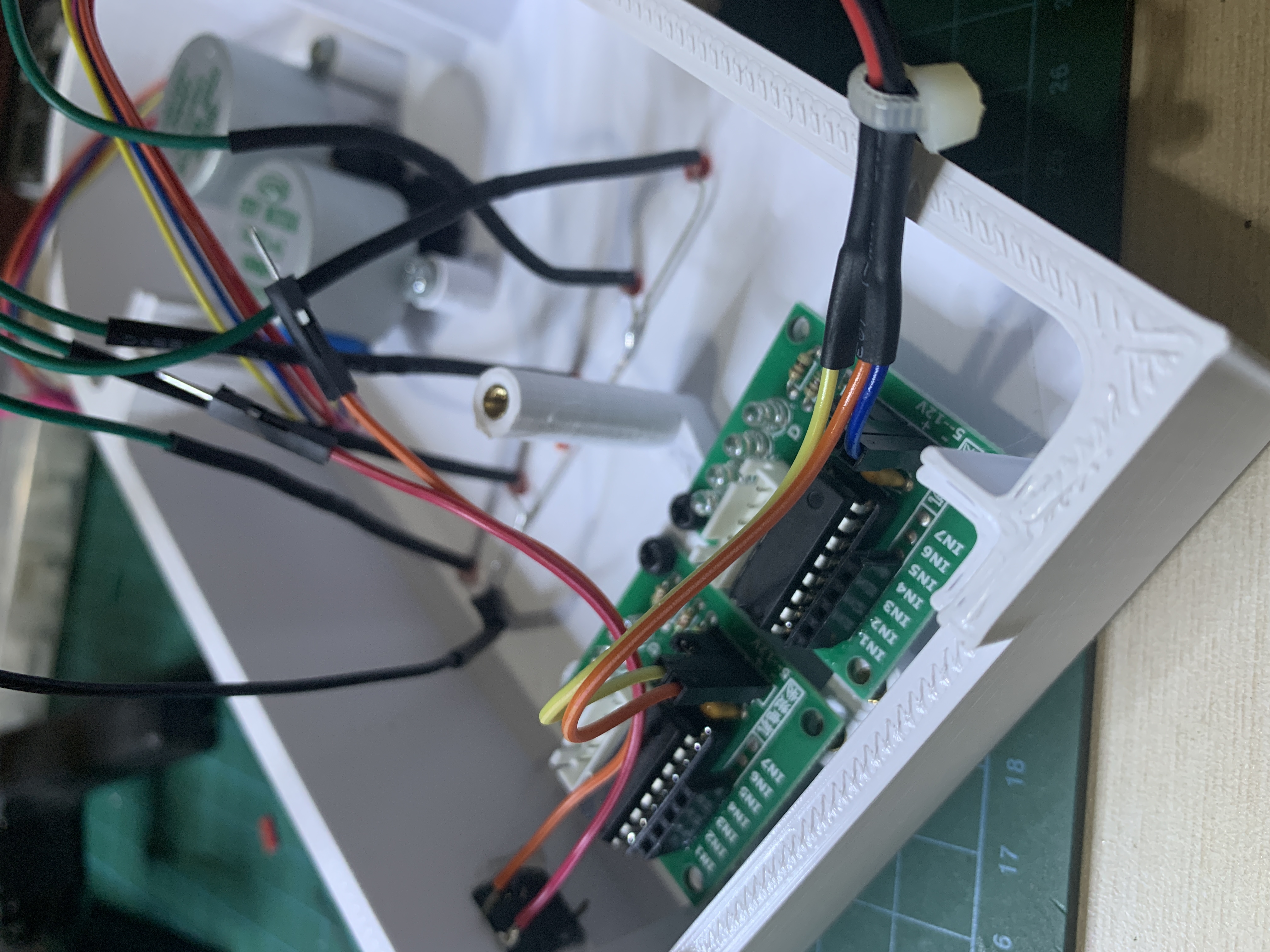
Solder female jumper splitter. This is necessary to supply 12V DC power to both of the ULN2003a motor drivers.
Solder female jumper cable to the button and then mount it to the enclosure.
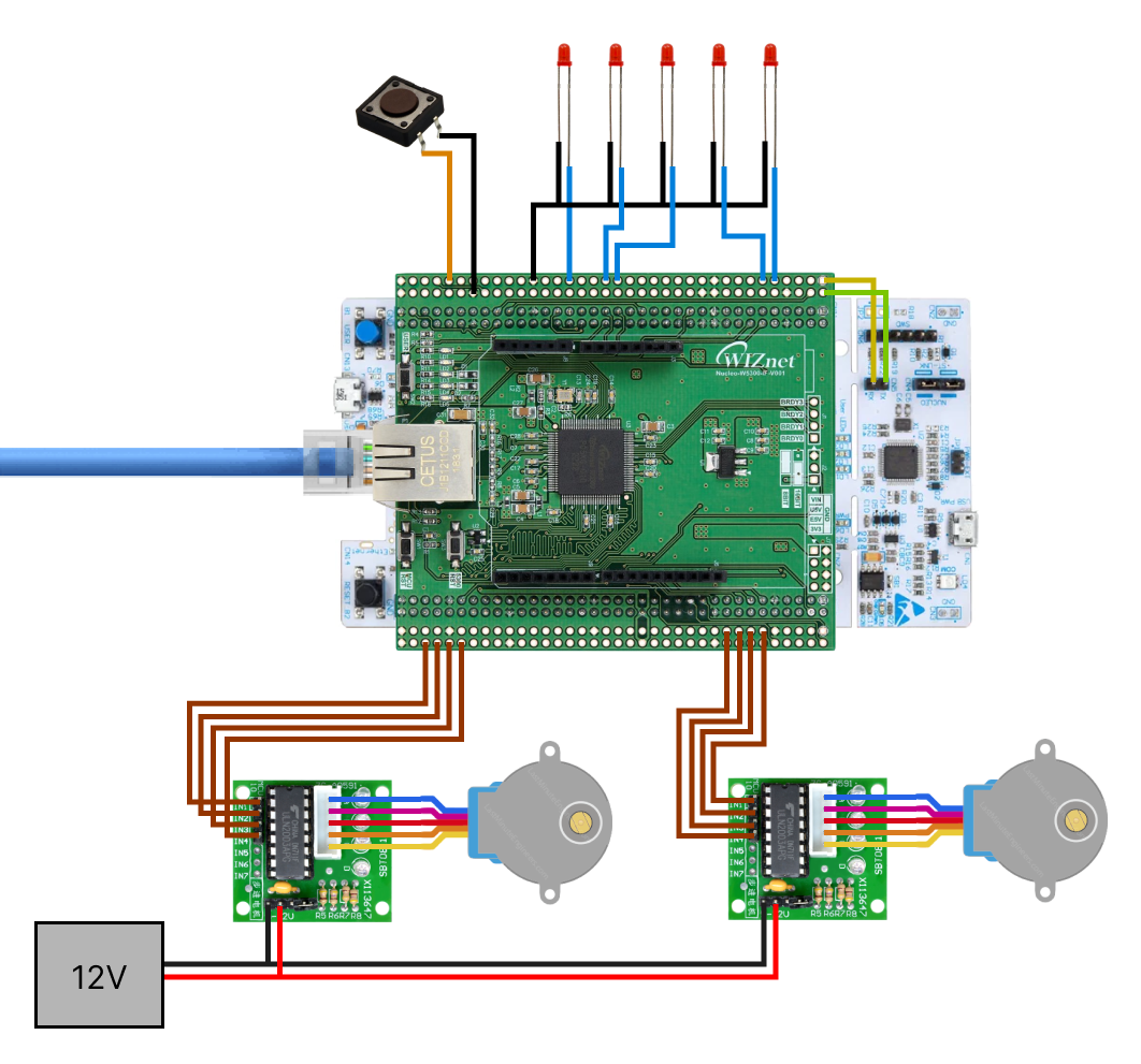
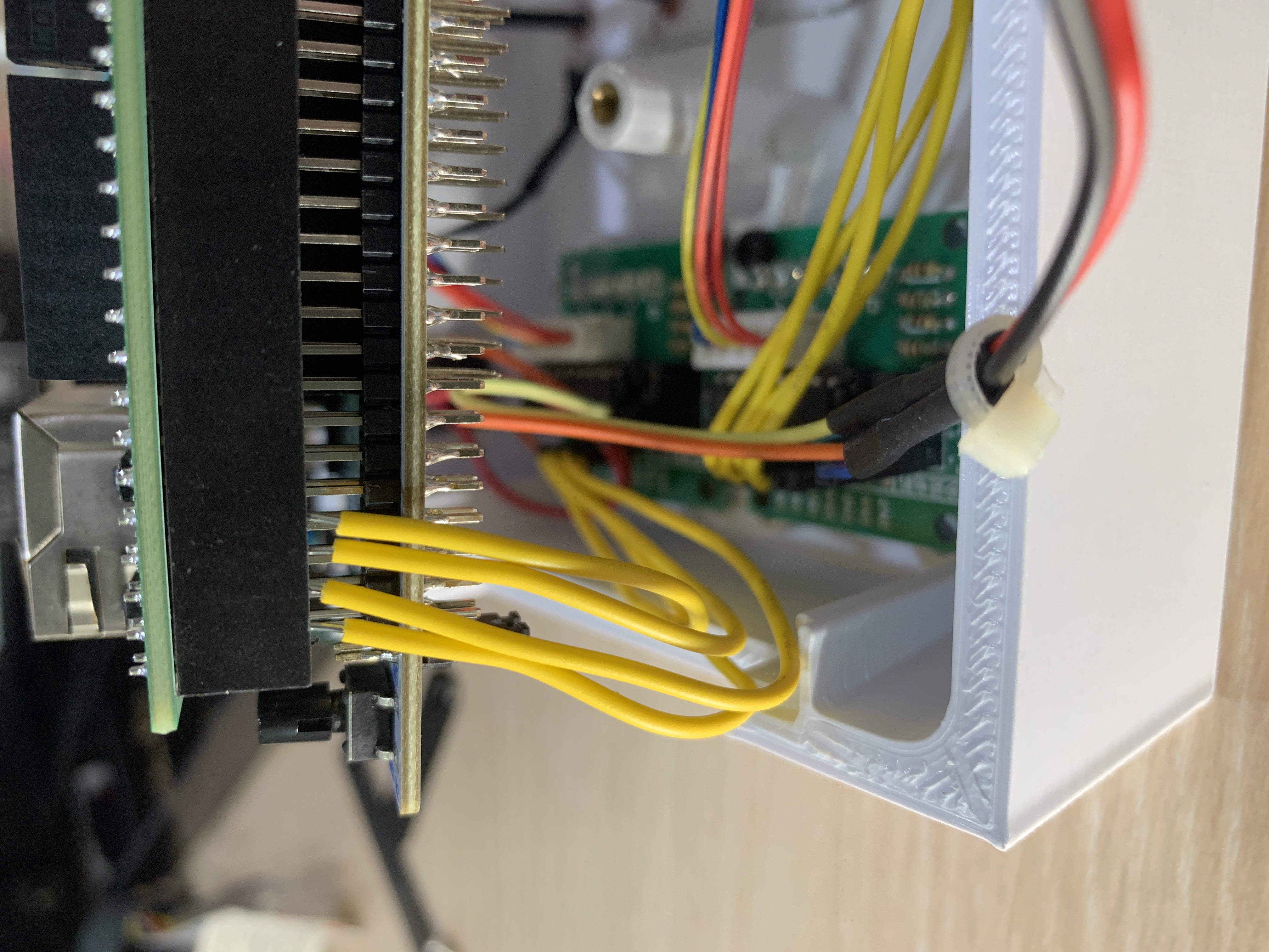
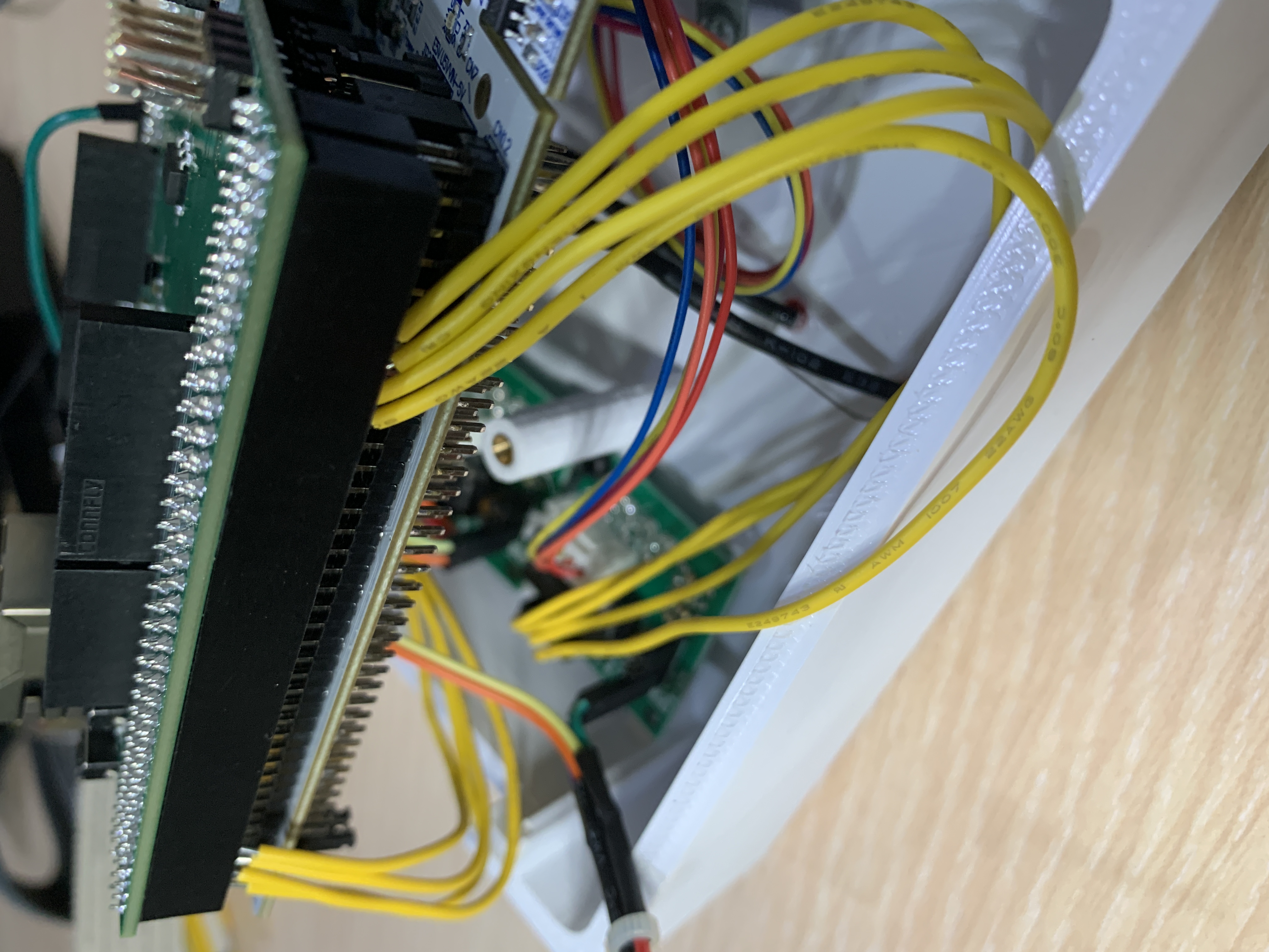
Wire the motors:
M1_IN1 = PG5
M1_IN2 = PG8
M1_IN3 = PE0
M1_IN4 = PF11
M2_IN1 = PA5
M2_IN2 = PA6
M2_IN3 = PA7
M2_IN4 = PB6
Wire the LEDs and Button:
LED_1 = PF6
LED_2 = PF7
LED_3 = PC2
LED_4 = PC3
LED_5 = PD6
BUT_1 = PG9
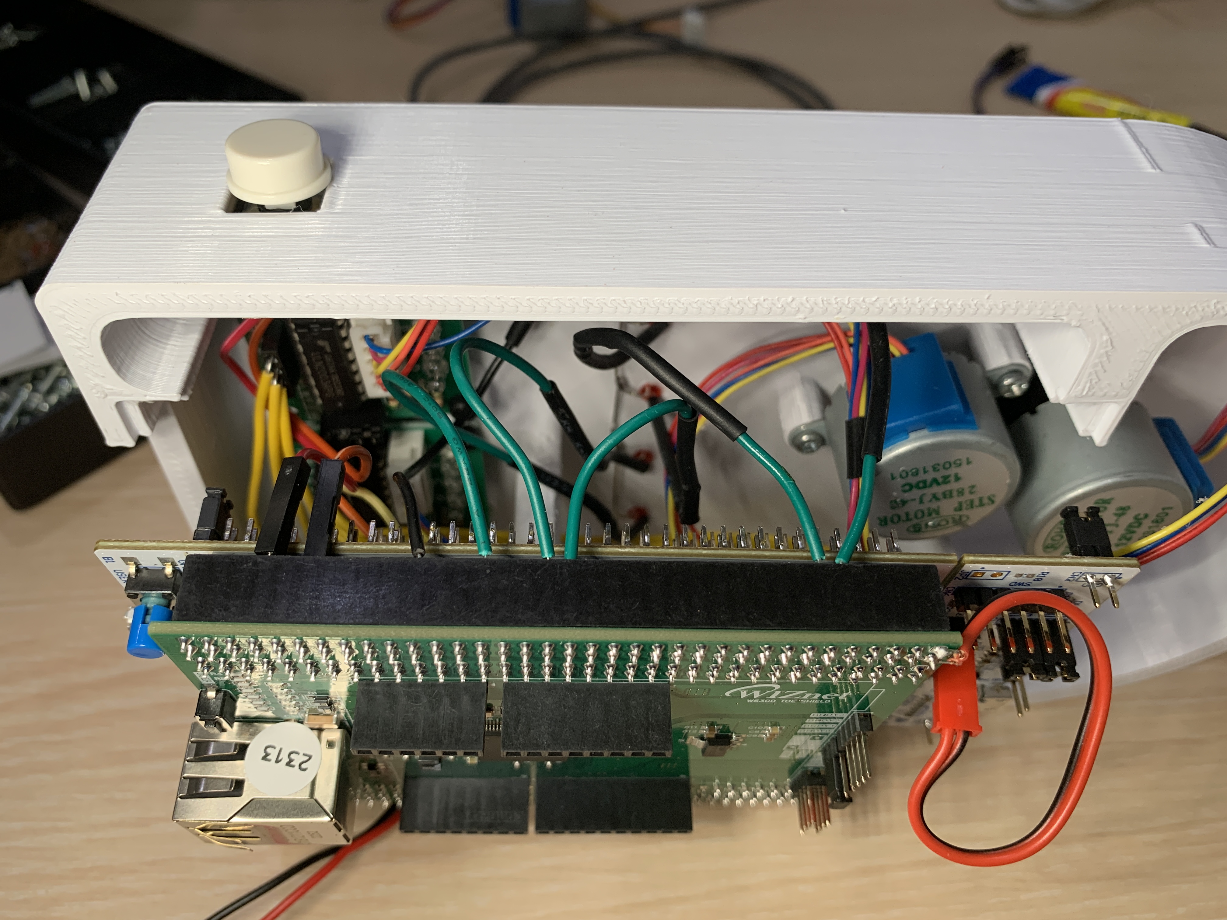
Add labels of the 5 cities.
Step 5: Code
Let's start by creating all the requirements to actuate the stepper motors. We will to create delay in microseconds using &htim1 we have setup in the config file.
void delay (uint16_t us)
{
  __HAL_TIM_SET_COUNTER(&htim1, 0);
  while (__HAL_TIM_GET_COUNTER(&htim1) < us);
}
Define the number of steps for 1 rull revolution.
#define stepsperrev 4096Function to set RPM of each motors individually.
void stepper1_set_rpm (int rpm)
{
	delay(60000000/stepsperrev/rpm);
}

void stepper2_set_rpm (int rpm)
{
	delay(60000000/stepsperrev/rpm);
}
We will use half-drive for the stepper motors because it provides the right balance of torque and angular resolution for this application. We will create a function to go through the 8 steps the driver needs to complete 1 sequence in half drive.
void stepper1_half_drive (int step)
{
	switch (step){
		case 0:
			  HAL_GPIO_WritePin(GPIOG, GPIO_PIN_5, GPIO_PIN_SET);   // IN1
			  HAL_GPIO_WritePin(GPIOG, GPIO_PIN_8, GPIO_PIN_RESET);   // IN2
			  HAL_GPIO_WritePin(GPIOE, GPIO_PIN_0, GPIO_PIN_RESET);   // IN3
			  HAL_GPIO_WritePin(GPIOF, GPIO_PIN_11, GPIO_PIN_RESET);   // IN4
			  break;

		case 1:
			  HAL_GPIO_WritePin(GPIOG, GPIO_PIN_5, GPIO_PIN_SET);   // IN1
			  HAL_GPIO_WritePin(GPIOG, GPIO_PIN_8, GPIO_PIN_SET);   // IN2
			  HAL_GPIO_WritePin(GPIOE, GPIO_PIN_0, GPIO_PIN_RESET);   // IN3
			  HAL_GPIO_WritePin(GPIOF, GPIO_PIN_11, GPIO_PIN_RESET);   // IN4
			  break;

		case 2:
			  HAL_GPIO_WritePin(GPIOG, GPIO_PIN_5, GPIO_PIN_RESET);   // IN1
			  HAL_GPIO_WritePin(GPIOG, GPIO_PIN_8, GPIO_PIN_SET);   // IN2
			  HAL_GPIO_WritePin(GPIOE, GPIO_PIN_0, GPIO_PIN_RESET);   // IN3
			  HAL_GPIO_WritePin(GPIOF, GPIO_PIN_11, GPIO_PIN_RESET);   // IN4
			  break;

		case 3:
			  HAL_GPIO_WritePin(GPIOG, GPIO_PIN_5, GPIO_PIN_RESET);   // IN1
			  HAL_GPIO_WritePin(GPIOG, GPIO_PIN_8, GPIO_PIN_SET);   // IN2
			  HAL_GPIO_WritePin(GPIOE, GPIO_PIN_0, GPIO_PIN_SET);   // IN3
			  HAL_GPIO_WritePin(GPIOF, GPIO_PIN_11, GPIO_PIN_RESET);   // IN4
			  break;

		case 4:
			  HAL_GPIO_WritePin(GPIOG, GPIO_PIN_5, GPIO_PIN_RESET);   // IN1
			  HAL_GPIO_WritePin(GPIOG, GPIO_PIN_8, GPIO_PIN_RESET);   // IN2
			  HAL_GPIO_WritePin(GPIOE, GPIO_PIN_0, GPIO_PIN_SET);   // IN3
			  HAL_GPIO_WritePin(GPIOF, GPIO_PIN_11, GPIO_PIN_RESET);   // IN4
			  break;

		case 5:
			  HAL_GPIO_WritePin(GPIOG, GPIO_PIN_5, GPIO_PIN_RESET);   // IN1
			  HAL_GPIO_WritePin(GPIOG, GPIO_PIN_8, GPIO_PIN_RESET);   // IN2
			  HAL_GPIO_WritePin(GPIOE, GPIO_PIN_0, GPIO_PIN_SET);   // IN3
			  HAL_GPIO_WritePin(GPIOF, GPIO_PIN_11, GPIO_PIN_SET);   // IN4
			  break;

		case 6:
			  HAL_GPIO_WritePin(GPIOG, GPIO_PIN_5, GPIO_PIN_RESET);   // IN1
			  HAL_GPIO_WritePin(GPIOG, GPIO_PIN_8, GPIO_PIN_RESET);   // IN2
			  HAL_GPIO_WritePin(GPIOE, GPIO_PIN_0, GPIO_PIN_RESET);   // IN3
			  HAL_GPIO_WritePin(GPIOF, GPIO_PIN_11, GPIO_PIN_SET);   // IN4
			  break;

		case 7:
			  HAL_GPIO_WritePin(GPIOG, GPIO_PIN_5, GPIO_PIN_SET);   // IN1
			  HAL_GPIO_WritePin(GPIOG, GPIO_PIN_8, GPIO_PIN_RESET);   // IN2
			  HAL_GPIO_WritePin(GPIOE, GPIO_PIN_0, GPIO_PIN_RESET);   // IN3
			  HAL_GPIO_WritePin(GPIOF, GPIO_PIN_11, GPIO_PIN_SET);   // IN4
			  break;

		}
}

void stepper2_half_drive (int step)
{
	switch (step){
		case 0:
			  HAL_GPIO_WritePin(GPIOA, GPIO_PIN_5, GPIO_PIN_SET);   // IN1
			  HAL_GPIO_WritePin(GPIOA, GPIO_PIN_6, GPIO_PIN_RESET);   // IN2
			  HAL_GPIO_WritePin(GPIOA, GPIO_PIN_7, GPIO_PIN_RESET);   // IN3
			  HAL_GPIO_WritePin(GPIOB, GPIO_PIN_6, GPIO_PIN_RESET);   // IN4
			  break;

		case 1:
			  HAL_GPIO_WritePin(GPIOA, GPIO_PIN_5, GPIO_PIN_SET);   // IN1
			  HAL_GPIO_WritePin(GPIOA, GPIO_PIN_6, GPIO_PIN_SET);   // IN2
			  HAL_GPIO_WritePin(GPIOA, GPIO_PIN_7, GPIO_PIN_RESET);   // IN3
			  HAL_GPIO_WritePin(GPIOB, GPIO_PIN_6, GPIO_PIN_RESET);   // IN4
			  break;

		case 2:
			  HAL_GPIO_WritePin(GPIOA, GPIO_PIN_5, GPIO_PIN_RESET);   // IN1
			  HAL_GPIO_WritePin(GPIOA, GPIO_PIN_6, GPIO_PIN_SET);   // IN2
			  HAL_GPIO_WritePin(GPIOA, GPIO_PIN_7, GPIO_PIN_RESET);   // IN3
			  HAL_GPIO_WritePin(GPIOB, GPIO_PIN_6, GPIO_PIN_RESET);   // IN4
			  break;

		case 3:
			  HAL_GPIO_WritePin(GPIOA, GPIO_PIN_5, GPIO_PIN_RESET);   // IN1
			  HAL_GPIO_WritePin(GPIOA, GPIO_PIN_6, GPIO_PIN_SET);   // IN2
			  HAL_GPIO_WritePin(GPIOA, GPIO_PIN_7, GPIO_PIN_SET);   // IN3
			  HAL_GPIO_WritePin(GPIOB, GPIO_PIN_6, GPIO_PIN_RESET);   // IN4
			  break;

		case 4:
			  HAL_GPIO_WritePin(GPIOA, GPIO_PIN_5, GPIO_PIN_RESET);   // IN1
			  HAL_GPIO_WritePin(GPIOA, GPIO_PIN_6, GPIO_PIN_RESET);   // IN2
			  HAL_GPIO_WritePin(GPIOA, GPIO_PIN_7, GPIO_PIN_SET);   // IN3
			  HAL_GPIO_WritePin(GPIOB, GPIO_PIN_6, GPIO_PIN_RESET);   // IN4
			  break;

		case 5:
			  HAL_GPIO_WritePin(GPIOA, GPIO_PIN_5, GPIO_PIN_RESET);   // IN1
			  HAL_GPIO_WritePin(GPIOA, GPIO_PIN_6, GPIO_PIN_RESET);   // IN2
			  HAL_GPIO_WritePin(GPIOA, GPIO_PIN_7, GPIO_PIN_SET);   // IN3
			  HAL_GPIO_WritePin(GPIOB, GPIO_PIN_6, GPIO_PIN_SET);   // IN4
			  break;

		case 6:
			  HAL_GPIO_WritePin(GPIOA, GPIO_PIN_5, GPIO_PIN_RESET);   // IN1
			  HAL_GPIO_WritePin(GPIOA, GPIO_PIN_6, GPIO_PIN_RESET);   // IN2
			  HAL_GPIO_WritePin(GPIOA, GPIO_PIN_7, GPIO_PIN_RESET);   // IN3
			  HAL_GPIO_WritePin(GPIOB, GPIO_PIN_6, GPIO_PIN_SET);   // IN4
			  break;

		case 7:
			  HAL_GPIO_WritePin(GPIOA, GPIO_PIN_5, GPIO_PIN_SET);   // IN1
			  HAL_GPIO_WritePin(GPIOA, GPIO_PIN_6, GPIO_PIN_RESET);   // IN2
			  HAL_GPIO_WritePin(GPIOA, GPIO_PIN_7, GPIO_PIN_RESET);   // IN3
			  HAL_GPIO_WritePin(GPIOB, GPIO_PIN_6, GPIO_PIN_SET);   // IN4
			  break;

		}
}
Now the function that takes the hour and minute, convert it into number of sequences, and then moves the motor.
void stepper1_step_angle (int minute, int direction, float rpm)
{
	float anglepersequence = 0.703125;  // 360 = 512 sequences
	float angle = (minute*6)
	int numberofsequences = (int) (angle/anglepersequence);

	for (int seq=0; seq<numberofsequences; seq++)
	{
		if (direction == 0)  // for clockwise
		{
			for (int step=7; step>=0; step--)
			{
				stepper1_half_drive(step);
				stepper1_set_rpm(rpm);
			}

		}

		else if (direction == 1)  // for anti-clockwise
		{
			for (int step=0; step<8; step++)
			{
				stepper1_half_drive(step);
				stepper1_set_rpm(rpm);
			}
		}
	}
}

void stepper2_step_angle (int hour, int minute, int direction, float rpm)
{
	float anglepersequence = 0.703125;  // 360 = 512 sequences
	float angle = (hour*30)+(minute*0.5)
	int numberofsequences = (int) (angle/anglepersequence);

	for (int seq=0; seq<numberofsequences; seq++)
	{
		if (direction == 0)  // for clockwise
		{
			for (int step=7; step>=0; step--)
			{
				stepper1_half_drive(step);
				stepper1_set_rpm(rpm);
			}

		}

		else if (direction == 1)  // for anti-clockwise
		{
			for (int step=0; step<8; step++)
			{
				stepper1_half_drive(step);
				stepper1_set_rpm(rpm);
			}
		}
	}
}
Lastly we need to be able to toggle between cities using the button.
if (HAL_GPIO_ReadPin(GPIOG, GPIO_PIN_9) == 0)
	  {
		  buttonPresses++;
		  HAL_Delay(250);								//debounce switch
	  }

	  if (buttonPresses == 5) buttonPresses = 0;
	  if (lastPressCount != buttonPresses)
	  {
		  if (buttonPresses == 1){
			  HAL_GPIO_WritePin(GPIOF, GPIO_PIN_6, GPIO_PIN_SET);
			  HAL_GPIO_WritePin(GPIOF, GPIO_PIN_7, GPIO_PIN_RESET);
			  HAL_GPIO_WritePin(GPIOC, GPIO_PIN_2, GPIO_PIN_RESET);
			  HAL_GPIO_WritePin(GPIOC, GPIO_PIN_3, GPIO_PIN_RESET);
			  HAL_GPIO_WritePin(GPIOD, GPIO_PIN_6, GPIO_PIN_RESET);
		  }
		  else if (buttonPresses == 2){
			  HAL_GPIO_WritePin(GPIOF, GPIO_PIN_6, GPIO_PIN_RESET);
			  HAL_GPIO_WritePin(GPIOF, GPIO_PIN_7, GPIO_PIN_SET);
			  HAL_GPIO_WritePin(GPIOC, GPIO_PIN_2, GPIO_PIN_RESET);
			  HAL_GPIO_WritePin(GPIOC, GPIO_PIN_3, GPIO_PIN_RESET);
			  HAL_GPIO_WritePin(GPIOD, GPIO_PIN_6, GPIO_PIN_RESET);
		  }
		  else if (buttonPresses == 3){
			  HAL_GPIO_WritePin(GPIOF, GPIO_PIN_6, GPIO_PIN_RESET);
			  HAL_GPIO_WritePin(GPIOF, GPIO_PIN_7, GPIO_PIN_RESET);
			  HAL_GPIO_WritePin(GPIOC, GPIO_PIN_2, GPIO_PIN_SET);
			  HAL_GPIO_WritePin(GPIOC, GPIO_PIN_3, GPIO_PIN_RESET);
			  HAL_GPIO_WritePin(GPIOD, GPIO_PIN_6, GPIO_PIN_RESET);
		  }
		  else if (buttonPresses == 4){
			  HAL_GPIO_WritePin(GPIOF, GPIO_PIN_6, GPIO_PIN_RESET);
			  HAL_GPIO_WritePin(GPIOF, GPIO_PIN_7, GPIO_PIN_RESET);
			  HAL_GPIO_WritePin(GPIOC, GPIO_PIN_2, GPIO_PIN_RESET);
			  HAL_GPIO_WritePin(GPIOC, GPIO_PIN_3, GPIO_PIN_SET);
			  HAL_GPIO_WritePin(GPIOD, GPIO_PIN_6, GPIO_PIN_RESET);
		  }
		  else{
			  HAL_GPIO_WritePin(GPIOF, GPIO_PIN_6, GPIO_PIN_RESET);
			  HAL_GPIO_WritePin(GPIOF, GPIO_PIN_7, GPIO_PIN_RESET);
			  HAL_GPIO_WritePin(GPIOC, GPIO_PIN_2, GPIO_PIN_RESET);
			  HAL_GPIO_WritePin(GPIOC, GPIO_PIN_3, GPIO_PIN_RESET);
			  HAL_GPIO_WritePin(GPIOD, GPIO_PIN_6, GPIO_PIN_SET);
		  }
		   stepper1_step_angle(time.mm, 0, 2);
		   stepper2_step_angle(time.hh, time.mm, 0, 2);
		   lastPressCount = buttonPresses;
	  }
Step 6: Plug in the power and Ethernet cable.
Congratulations! You have built yourself an IoT World-Clock!
-
face.stl

-
hourgear.stl
-
hourgearmount.stl
-
hourhand.stl
-
minutehand.stl
-
minutemount.stl
-
Wiring Diagram
.png)