WizFi360-EVB-Mini Pulse Oximeter Blynk BPM
I'll build a pulse oximeter using MAX30102 and WizFi360-EVB-Mini that will track the Blood Oxygen level and send the data via Wi-Fi.
WIZnet - WizFi360-EVB-Mini
x 1

DFRobot - Maxim Integrated MAX30102 High-Sensitivity Pulse Oximeter and Heart-Rate Sensor for Wearable Health
x 1

seeed - Grove - Universal 4 Pin Buckled 5cm Cable (5 PCs Pack)
x 10

Arduino - Arduino IDE
x 1
WIZnet - WIZnet WizFi Library
x 1
blynk - Blynk
x 1
WizFi360-EVB-Mini Pulse Oximeter Blynk BPM
I'll build a pulse oximeter using MAX30102 and WizFi360-EVB-Mini that will track the Blood Oxygen level and send the data via Wi-Fi.

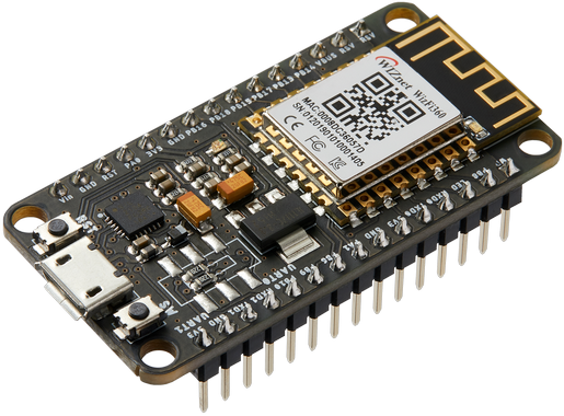
WizFi360-EVB-Mini Hardware Overview
Thanks to WIZnet for supporting this project with WizFi360-EVB-Mini Hardware.
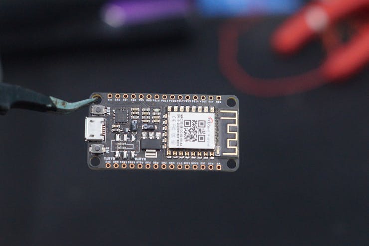
This document describes WizFi360-EVB-Mini. WizFi360-EVB-Mini is a compact development board for experimenting, testing, and verification of WizFi360. WizFi360-EVB-Mini is the same form factor as the NodeMCU V2. WizFi360 is a low-cost and low-power consumption industrial-grade WiFi module. It is compatible with IEEE802.11 b/g/n standard and supports SoftAP, Station, and SoftAP+Station modes. The serial port baud rate can be up to 2Mbps, which can meet the requirement of various applications.
https://docs.wiznet.io/Product/Wi-Fi-Module/WizFi360/wizfi360_evb_mini
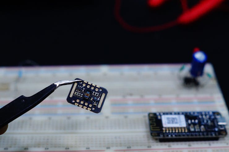
MAX30102
The MAX30102 is an integrated pulse oximeter and heart rate monitor Sensor. It integrates a red LED and an infrared LED, photoelectric detectors, optical devices, and low-noise electronic circuits with ambient light suppression. Standard I2C compatible communication interface can transfer the collected values to the WizFi360-EVB-Mini for heart rate and blood oxygen calculation.
- Photo-dissolution method
- Light transmittance is converted into an electrical signal
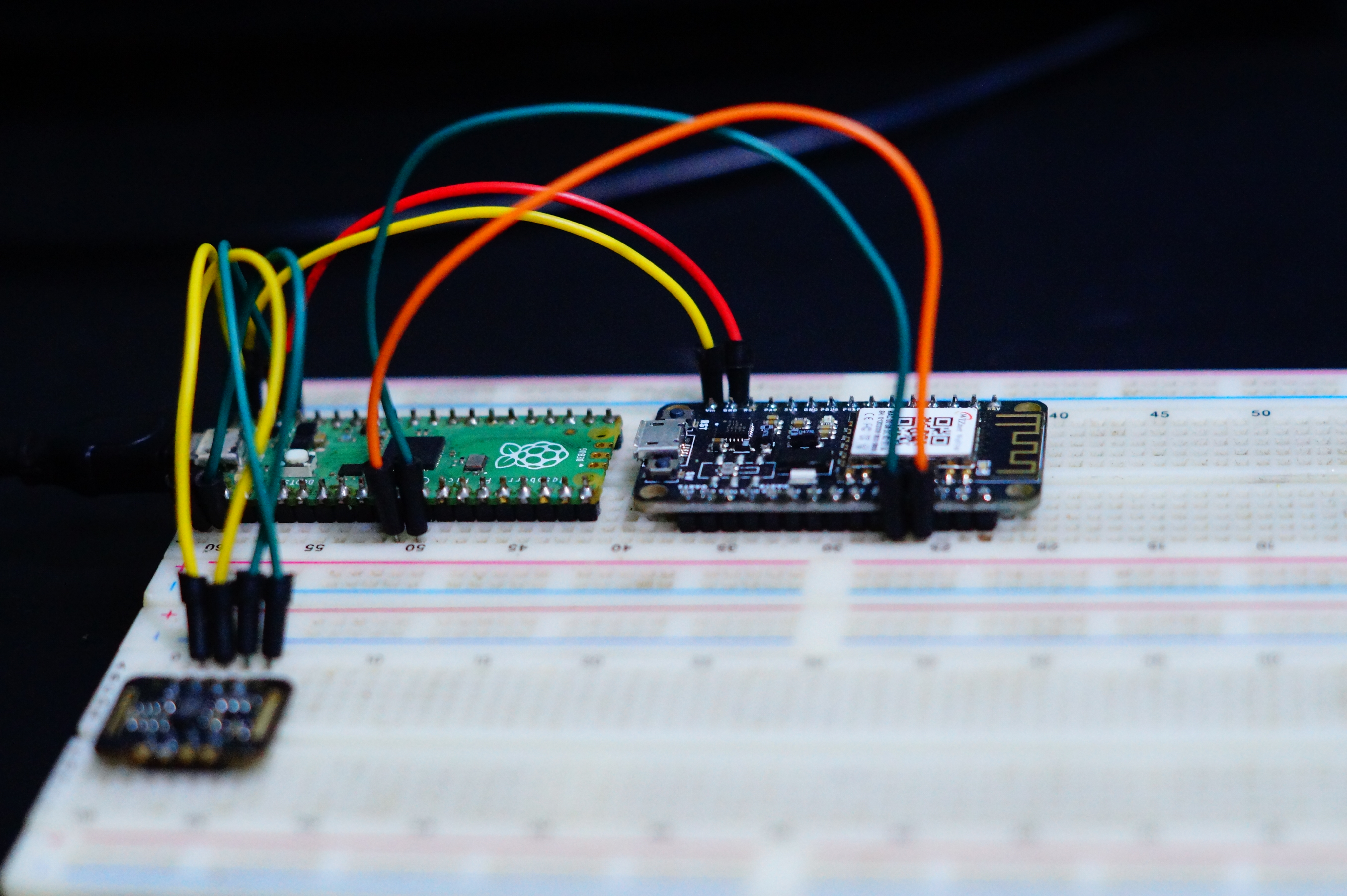
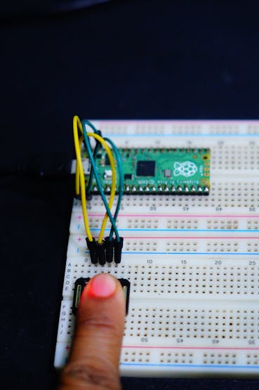
Wiring up a MAX30102 Module & WizFi360-EVB-Mini to Raspberry Pi Pico
- Connect the VCC pin to the power supply, GND to GND.
- Connect the SCL pin to the I2C clock pin and the SDA pin to the I2C data pin on Raspberry Pi Pico.
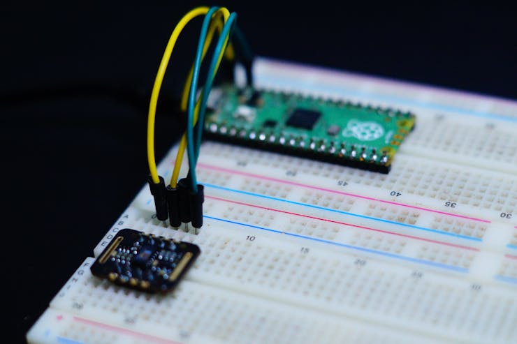
- Connect the Vin pin to the power supply, GND to GND.
- Connect the TXD1 pin to the IO9 pin and the RXD1 pin to the IO8 pin on Raspberry Pi Pico.

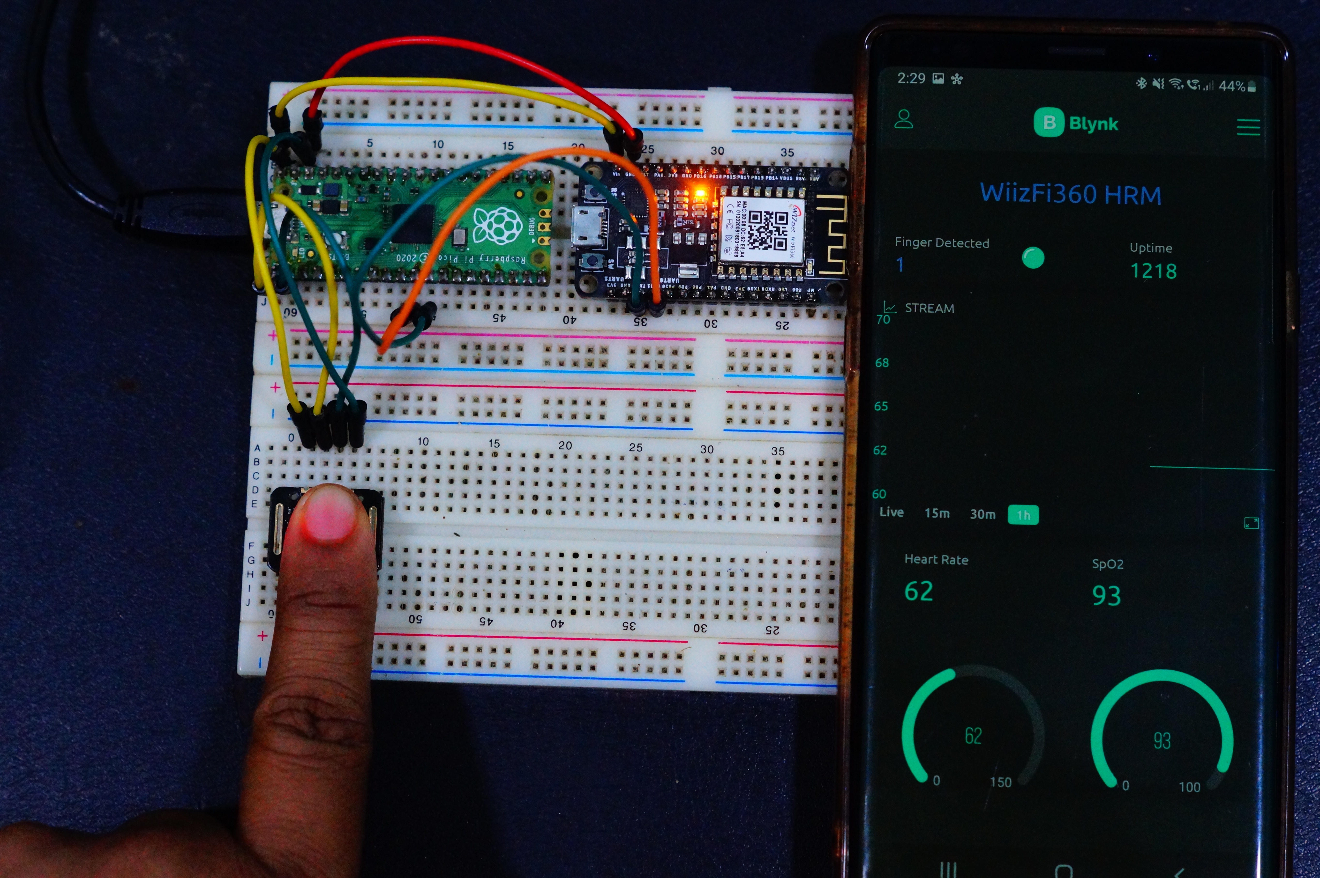
It is best to attach the sensor to your finger using a rubber band or Velcro. When you press your finger against the sensor it varies enough to cause the blood in your finger to flow differently which makes the sensor readings unstable.
- Install the MAX30102 library from Sparkfun
_wlnSiVnIgf.png?auto=compress%2Cformat&w=740&h=555&fit=max)
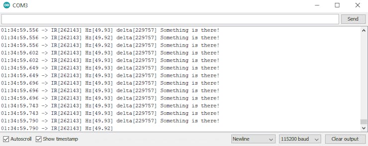
We continuously print the delta values to find the difference
void loop()
{
  samplesTaken++;

  Serial.print("IR[");
  Serial.print(particleSensor.getIR());
  Serial.print("] Hz[");
  Serial.print((float)samplesTaken / ((millis() - startTime) / 1000.0), 2);
  Serial.print("]");

  long currentDelta = particleSensor.getIR() - unblockedValue;

  Serial.print(" delta[");
  Serial.print(currentDelta);
  Serial.print("]");

  if (currentDelta > (long)100)
  {
    Serial.print(" Something is there!");
  }

  Serial.println();
}
The Serial output is printed as shown.
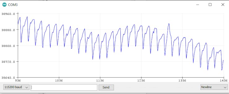
Display Heartbeat Waveform
Display heartbeat diagram on the Arduino serial plotter. Click tool->Serial Plotter.
#include <Wire.h>
#include "MAX30105.h"

MAX30105 particleSensor;

void setup()
{
  Serial.begin(115200);
  Serial.println("Initializing...");

  // Initialize sensor
  if (!particleSensor.begin(Wire, I2C_SPEED_FAST)) //Use default I2C port, 400kHz speed
  {
    Serial.println("MAX30105 was not found. Please check wiring/power. ");
    while (1);
  }

  //Setup to sense a nice looking saw tooth on the plotter
  byte ledBrightness = 0x1F; //Options: 0=Off to 255=50mA
  byte sampleAverage = 8; //Options: 1, 2, 4, 8, 16, 32
  byte ledMode = 3; //Options: 1 = Red only, 2 = Red + IR, 3 = Red + IR + Green
  int sampleRate = 100; //Options: 50, 100, 200, 400, 800, 1000, 1600, 3200
  int pulseWidth = 411; //Options: 69, 118, 215, 411
  int adcRange = 4096; //Options: 2048, 4096, 8192, 16384

  particleSensor.setup(ledBrightness, sampleAverage, ledMode, sampleRate, pulseWidth, adcRange); //Configure sensor with these settings

  //Take an average of IR readings at power up
  const byte avgAmount = 64;
  long baseValue = 0;
  for (byte x = 0 ; x < avgAmount ; x++)
  {
    baseValue += particleSensor.getIR(); //Read the IR value
  }
  baseValue /= avgAmount;

  //Pre-populate the plotter so that the Y scale is close to IR values
  for (int x = 0 ; x < 500 ; x++)
    Serial.println(baseValue);
}

void loop()
{
  Serial.println(particleSensor.getIR()); //Send raw data to plotter
}
The waveform is plotted using the Serial plotter.
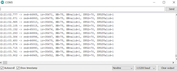
Display the heart rate and SPO2 on Arduino serial monitor. The ideal heart rate(adult): 60~100 beats per minute and the ideal SPO2: 95~100.
{
      while (particleSensor.available() == false) //do we have new data?
        particleSensor.check(); //Check the sensor for new data

      digitalWrite(readLED, !digitalRead(readLED)); //Blink onboard LED with every data read

      redBuffer[i] = particleSensor.getRed();
      irBuffer[i] = particleSensor.getIR();
      particleSensor.nextSample(); //We're finished with this sample so move to next sample

      //send samples and calculation result to terminal program through UART
      Serial.print(F("red="));
      Serial.print(redBuffer[i], DEC);
      Serial.print(F(", ir="));
      Serial.print(irBuffer[i], DEC);

      Serial.print(F(", HR="));
      Serial.print(heartRate, DEC);

      Serial.print(F(", HRvalid="));
      Serial.print(validHeartRate, DEC);

      Serial.print(F(", SPO2="));
      Serial.print(spo2, DEC);

      Serial.print(F(", SPO2Valid="));
      Serial.println(validSPO2, DEC);
    }
Programming WizFi360-EVB-Mini
We will programming the WizFi360-EVB-Mini using the AT commands. We will be using multiple serial ports to communicate with USB and with WizFi360-EVB-Mini.
Serial2.println("AT\r\n"); //Handshaking with WizFi360-EVB-MiniThe WizFi360-EVB-MIni responds to the AT commands as shown.
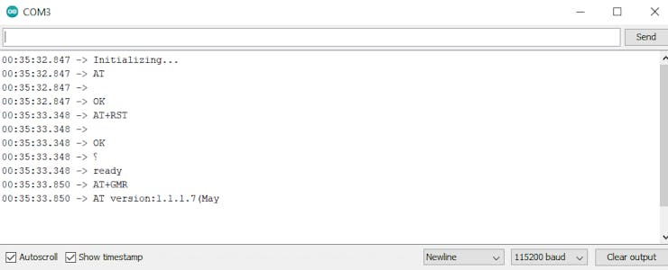
We had installed the WizFi360 and WiFiEsp library from Wiznet that connects the module to the WiFi and then to Blynk.
_JVJxMvxbus.png?auto=compress%2Cformat&w=740&h=555&fit=max)
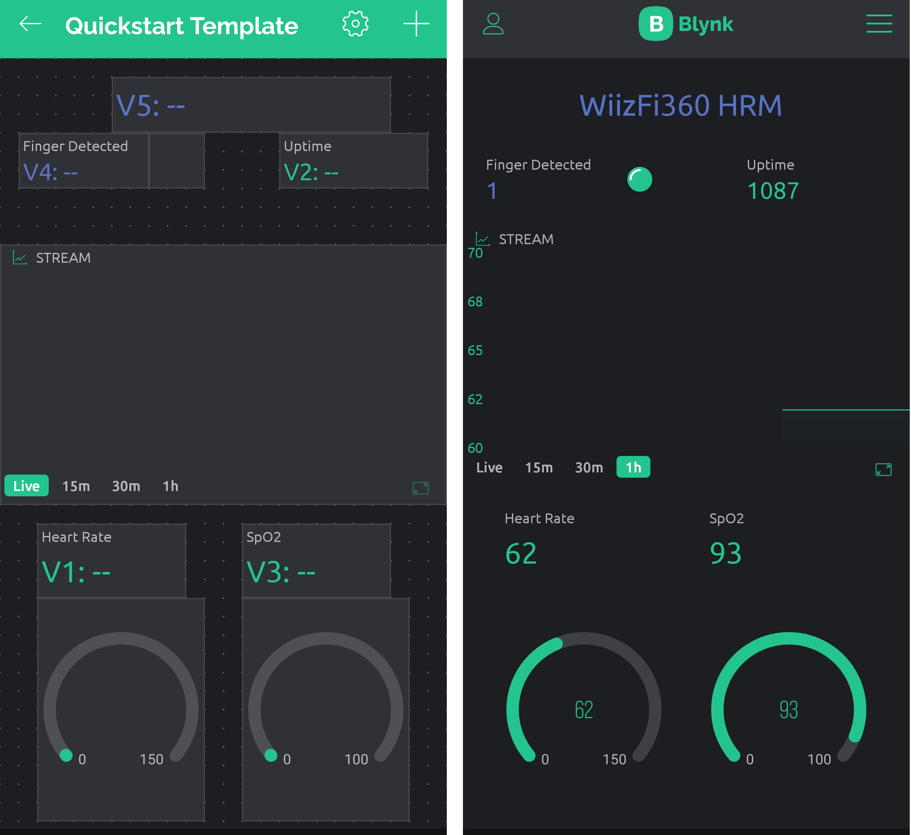
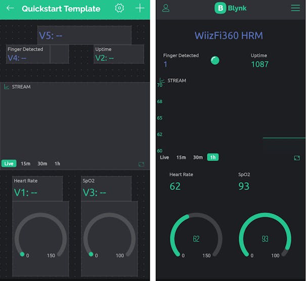
Setting up Blynk Application for IoT Pulse Oximeter
- Download the Blynk app (App Store, Google Play)
- Get the Auth Token from the app
- Import this library to Arduino IDE
_ERF5HyIi06.png?auto=compress%2Cformat&w=740&h=555&fit=max)
Set the DataStream as shown below
_erfDMb4aJ8.png?auto=compress%2Cformat&w=740&h=555&fit=max)
_Lpwjsm2dCO.png?auto=compress%2Cformat&w=740&h=555&fit=max)
- Arduino Library https://github.com/Wiznet/WizFi360_arduino_library
- WizFi360-EVB-Mini https://docs.wiznet.io/Product/Wi-Fi-Module/WizFi360/wizfi360_evb_mini
- https://github.com/Wiznet/Hardware-Files-of-WIZnet/blob/master/07_WizFi_Module/WizFi360-EVB-Mini/WizFi360-EVB-Mini_V100/Schematic/WizFi360-EVB-mini_SCH_V100.pdf
-
WizFi360-EVB-Mini_Pulse_Oximeter_Blynk BPM.ino

-
MAX30102.ino
-
Connections
-
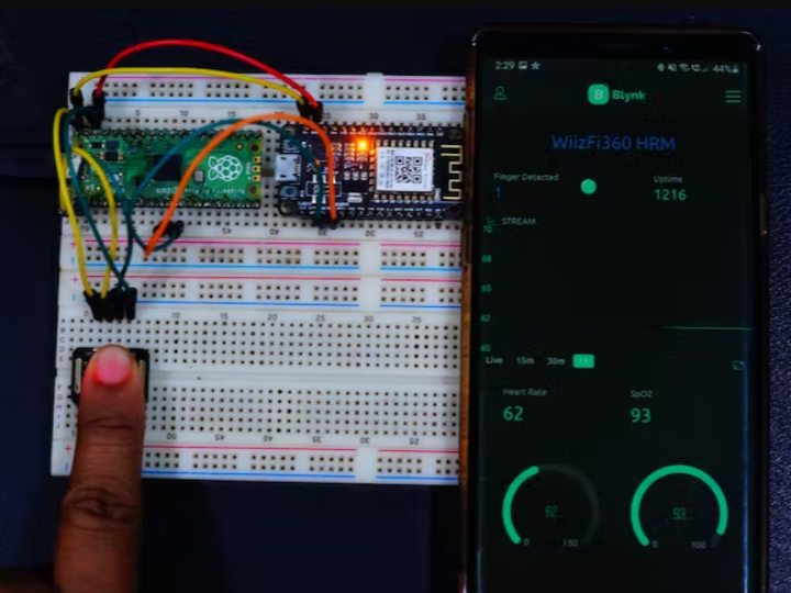
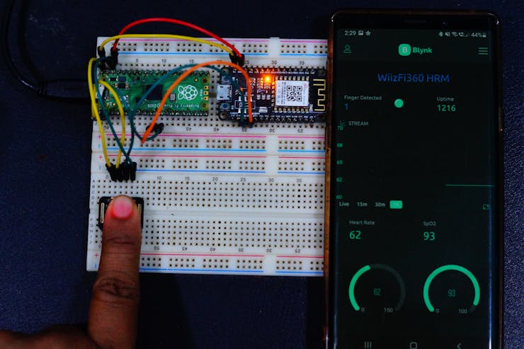
Final output
-
Dashboard